EP4471192A2 - Système d'enroulement de filage et unité d'assistance au filetage de fil - Google Patents
Système d'enroulement de filage et unité d'assistance au filetage de fil Download PDFInfo
- Publication number
- EP4471192A2 EP4471192A2 EP24176707.8A EP24176707A EP4471192A2 EP 4471192 A2 EP4471192 A2 EP 4471192A2 EP 24176707 A EP24176707 A EP 24176707A EP 4471192 A2 EP4471192 A2 EP 4471192A2
- Authority
- EP
- European Patent Office
- Prior art keywords
- yarn
- spinning
- unit
- threading
- winding system
- Prior art date
- Legal status (The legal status is an assumption and is not a legal conclusion. Google has not performed a legal analysis and makes no representation as to the accuracy of the status listed.)
- Pending
Links
Images





Classifications
-
- D—TEXTILES; PAPER
- D01—NATURAL OR MAN-MADE THREADS OR FIBRES; SPINNING
- D01D—MECHANICAL METHODS OR APPARATUS IN THE MANUFACTURE OF ARTIFICIAL FILAMENTS, THREADS, FIBRES, BRISTLES OR RIBBONS
- D01D7/00—Collecting the newly-spun products
-
- B—PERFORMING OPERATIONS; TRANSPORTING
- B65—CONVEYING; PACKING; STORING; HANDLING THIN OR FILAMENTARY MATERIAL
- B65H—HANDLING THIN OR FILAMENTARY MATERIAL, e.g. SHEETS, WEBS, CABLES
- B65H51/00—Forwarding filamentary material
- B65H51/16—Devices for entraining material by flow of liquids or gases, e.g. air-blast devices
-
- B—PERFORMING OPERATIONS; TRANSPORTING
- B65—CONVEYING; PACKING; STORING; HANDLING THIN OR FILAMENTARY MATERIAL
- B65H—HANDLING THIN OR FILAMENTARY MATERIAL, e.g. SHEETS, WEBS, CABLES
- B65H57/00—Guides for filamentary materials; Supports therefor
- B65H57/12—Tubes
-
- D—TEXTILES; PAPER
- D01—NATURAL OR MAN-MADE THREADS OR FIBRES; SPINNING
- D01D—MECHANICAL METHODS OR APPARATUS IN THE MANUFACTURE OF ARTIFICIAL FILAMENTS, THREADS, FIBRES, BRISTLES OR RIBBONS
- D01D13/00—Complete machines for producing artificial threads
- D01D13/02—Elements of machines in combination
-
- D—TEXTILES; PAPER
- D01—NATURAL OR MAN-MADE THREADS OR FIBRES; SPINNING
- D01D—MECHANICAL METHODS OR APPARATUS IN THE MANUFACTURE OF ARTIFICIAL FILAMENTS, THREADS, FIBRES, BRISTLES OR RIBBONS
- D01D5/00—Formation of filaments, threads, or the like
- D01D5/08—Melt spinning methods
-
- D—TEXTILES; PAPER
- D01—NATURAL OR MAN-MADE THREADS OR FIBRES; SPINNING
- D01D—MECHANICAL METHODS OR APPARATUS IN THE MANUFACTURE OF ARTIFICIAL FILAMENTS, THREADS, FIBRES, BRISTLES OR RIBBONS
- D01D5/00—Formation of filaments, threads, or the like
- D01D5/08—Melt spinning methods
- D01D5/088—Cooling filaments, threads or the like, leaving the spinnerettes
-
- D—TEXTILES; PAPER
- D01—NATURAL OR MAN-MADE THREADS OR FIBRES; SPINNING
- D01D—MECHANICAL METHODS OR APPARATUS IN THE MANUFACTURE OF ARTIFICIAL FILAMENTS, THREADS, FIBRES, BRISTLES OR RIBBONS
- D01D5/00—Formation of filaments, threads, or the like
- D01D5/08—Melt spinning methods
- D01D5/088—Cooling filaments, threads or the like, leaving the spinnerettes
- D01D5/092—Cooling filaments, threads or the like, leaving the spinnerettes in shafts or chimneys
-
- D—TEXTILES; PAPER
- D02—YARNS; MECHANICAL FINISHING OF YARNS OR ROPES; WARPING OR BEAMING
- D02G—CRIMPING OR CURLING FIBRES, FILAMENTS, THREADS, OR YARNS; YARNS OR THREADS
- D02G1/00—Producing crimped or curled fibres, filaments, yarns, or threads, giving them latent characteristics
- D02G1/02—Producing crimped or curled fibres, filaments, yarns, or threads, giving them latent characteristics by twisting, fixing the twist and backtwisting, i.e. by imparting false twist
- D02G1/0206—Producing crimped or curled fibres, filaments, yarns, or threads, giving them latent characteristics by twisting, fixing the twist and backtwisting, i.e. by imparting false twist by false-twisting
- D02G1/0266—Producing crimped or curled fibres, filaments, yarns, or threads, giving them latent characteristics by twisting, fixing the twist and backtwisting, i.e. by imparting false twist by false-twisting false-twisting machines
- D02G1/0273—Producing crimped or curled fibres, filaments, yarns, or threads, giving them latent characteristics by twisting, fixing the twist and backtwisting, i.e. by imparting false twist by false-twisting false-twisting machines threading up and starting the false-twisting machine
-
- B—PERFORMING OPERATIONS; TRANSPORTING
- B65—CONVEYING; PACKING; STORING; HANDLING THIN OR FILAMENTARY MATERIAL
- B65H—HANDLING THIN OR FILAMENTARY MATERIAL, e.g. SHEETS, WEBS, CABLES
- B65H2701/00—Handled material; Storage means
- B65H2701/30—Handled filamentary material
- B65H2701/31—Textiles threads or artificial strands of filaments
- B65H2701/313—Synthetic polymer threads
- B65H2701/3132—Synthetic polymer threads extruded from spinnerets
Definitions
- the present invention relates to a spinning winding system and a yarn-threading assist unit that can be disposed in the spinning winding system.
- a spinning winding system includes a cooling unit below a spinning unit that spins a high-temperature molten polymer from a spinneret.
- the cooling unit includes a spinning cylinder that allows the high-temperature molten polymer spun from the spinneret to pass therethrough, and supplies cooling air to the spinning cylinder so as to blow the cooling air onto the high-temperature molten polymer and cool and solidify the high-temperature molten polymer, thereby to form a yarn.
- Patent Document 1 discloses a yarn cooling unit that is lowered to allow maintenance work such as replacing a spinning pack and surface cleaning to be performed.
- Patent Document 1 Japanese Patent Application Publication No. 2005-42227
- the spinning of the molten polymer from the spinneret is stopped. After maintenance has ended, the spinning of the molten polymer from the spinneret is restarted. After the spinning of the molten polymer is restarted, an operator performs a task of cutting the molten polymer spun from the spinneret by hand and threading the molten polymer through the spinning cylinder.
- the task of threading the molten polymer is difficult and requires skill.
- the molten polymer since the molten polymer will continue to be spun from the spinneret, the molten polymer that could not be thread through the spinning cylinder may accumulate in an upper portion of the cooling unit and it may take time to restart operation of the spinning winding system.
- the present invention has been made in light of the above-described problem, and it is an object of the present invention to provide a spinning winding system capable of facilitating yarn threading work, and a yarn-threading assist unit capable of facilitating yarn threading work performed at the spinning winding system.
- a first aspect of the present invention is a spinning winding system comprising:
- the yarn-threading assist unit is arranged with respect to the outlet portion for the yarn so that the spinning cylinder has a negative pressure formed therewithin, and a flow of air travelling from top to bottom inside is generated in the spinning cylinder so as to assist yarn threading work.
- a second aspect of the present invention is the spinning winding system, wherein the yarn-threading assist unit is preferably arranged so as to be pressed against the outlet portion for the yarn.
- the yarn-threading assist unit is arranged pressed against the outlet portion for the yarn, a negative pressure can be effectively formed inside the spinning cylinder.
- a third aspect of the present invention is the spinning winding system, wherein
- the molten polymer can be cooled and solidified by supplying the cooling air to the spinning cylinder and, when performing the yarn threading work with respect to the spinning cylinder, the supply of the cooling air to the spinning cylinder is preferably stopped or suppressed to suppress a drop in temperature of the spinneret and around the spinneret.
- the supply of the cooling air to the spinning cylinder is stopped or suppressed, yarn threading work to the spinning cylinder becomes difficult.
- a fourth aspect of the present invention is the spinning winding system, wherein
- the yarn-threading assist unit is configured to be arranged for each of the plurality of spinning cylinders, loss during yarn threading work can be reduced and yarn threading work can be facilitated.
- a fifth aspect of the present invention is the spinning winding system, wherein
- a sixth aspect of the present invention is the spinning winding system, wherein,
- a seventh aspect of the present invention is the spinning winding system, wherein the cylindrical portion preferably includes a trap portion configured to trap the yarn.
- a eighth aspect of the present invention is the spinning winding system, wherein
- the yarn threading work to the plurality of spinning cylinders can be assisted with one negative pressure source, costs can be reduced and the space required for installing the yarn-threading assist unit can be suppressed.
- a ninth aspect of the present invention is the spinning winding system, wherein the yarn-threading assist unit is preferably able to suction an inside of the spinning cylinder to generate a flow of air from above to below of the spinning cylinder.
- the suction inside the spinning cylinder can generate a flow of air from top to bottom, which makes the yarn threading work even easier.
- a tenth aspect of the present invention is the spinning winding system, preferably comprising
- the spinning winding system can be attached to and detached from any one of the spinning cylinders in the plurality of cooling units by being movably provided on the upper floor.
- the spinning winding system can be attached to and detached from any one of the spinning cylinders in the plurality of cooling units by being movably provided on the upper floor.
- An eleventh aspect of the present invention is a yarn-threading assist unit for assisting in yarn threading work with respect to a spinning winding system including:
- the yarn-threading assist unit when the yarn-threading assist unit is attached to the outlet portion for the yarn, a negative pressure is formed inside the spinning cylinder, which generates an air flow from top to bottom inside the spinning cylinder so as to assist yarn threading work.
- a negative pressure is formed inside the spinning cylinder, which generates an air flow from top to bottom inside the spinning cylinder so as to assist yarn threading work.
- a twelfth aspect of the present invention is the yarn-threading assist unit, wherein the yarn-threading assist unit is preferably arranged pressed against the outlet portion for the yarn.
- the yarn-threading assist unit since the yarn-threading assist unit is arranged pressed against the outlet portion for the yarn, a negative pressure can be efficiently formed inside the spinning cylinder.
- a thirteenth aspect of the present invention is the yarn-threading assist unit, wherein the yarn-threading assist unit preferably assists yarn threading work with respect to the spinning winding system further comprising a cooling air supply unit configured to supply cooling air to the spinning cylinder, and a control unit configured to stop or suppress supply of the cooling air at least when the yarn threading work is performed.
- the yarn-threading assist unit yarn threading work can be facilitated while suppressing a drop in temperature of the spinneret and an area around the spinneret.
- the molten polymer can be cooled and solidified by supplying the cooling air to the spinning cylinder and, when performing the yarn threading work with respect to the spinning cylinder, the supply of the cooling air to the spinning cylinder is preferably stopped or suppressed to suppress a drop in temperature of the spinneret and around the spinneret.
- the supply of the cooling air to the spinning cylinder is stopped or suppressed, yarn threading work to the spinning cylinder becomes difficult.
- a fourteenth aspect of the present invention is the yarn-threading assist unit, wherein
- the yarn-threading assist unit can be arranged for each of the plurality of spinning cylinders, loss during yarn threading work can be reduced and yarn threading work can be facilitated.
- a fifteenth aspect of the present invention is the yarn-threading assist unit preferably further including
- the yarn-threading assist unit since the yarn-threading assist unit is arranged pressed against the outlet portion for the yarn, a negative pressure can be efficiently formed inside the spinning cylinder.
- a sixteenth aspect of the present invention is the yarn-threading assist unit, wherein, in the cylindrical portion, an opening area of a portion pressed against the outlet portion for the yarn is preferably larger than an opening area of the outlet portion for the yarn.
- the cylindrical portion can be easily pushed against the outlet part for the yarn for connection.
- a seventeenth aspect of the present invention is the yarn-threading assist unit, wherein the cylindrical portion preferably includes a trap portion configured to trap the yarn.
- the yarn-threading assist unit since the yarn is trapped by the trap portion, it is possible to prevent problems with the yarn-threading assist unit that can be caused by the yarn.
- An eighteenth aspect of the present invention is the yarn-threading assist unit, wherein
- the yarn threading work to the plurality of spinning cylinders can be assisted with one negative pressure source, costs can be reduced and the space required for installing the yarn-threading assist unit can be suppressed.
- a nineteenth aspect of the present invention is the yarn-threading assist unit, wherein the yarn-threading assist unit is preferably able to suction an inside of the spinning cylinder to generate a flow of air from above to below of the spinning cylinder.
- the suction inside the spinning cylinder can generate a flow of air from top to bottom, which makes the yarn threading work even easier.
- a twentieth aspect of the present invention is the yarn-threading assist unit, wherein the spinning winding system is preferably configured such that
- the spinning winding system can be attached to and detached from any one of the spinning cylinders in the plurality of cooling units by being movably provided on the upper floor.
- the spinning winding system according to the present invention need not have all of the configurations described in first to tenth aspects above.
- the spinning winding system according to the present invention may only have the configuration described in the first aspect.
- the configuration described in the first aspect may be combined as desired with all or some of the configurations described in at least one of second to tenth aspects to complete the spinning winding system according to the present invention.
- the yarn-threading assist unit according to the present invention need not have all of the configurations described in the eleventh to twentieth aspects above.
- the yarn-threading assist unit according to the present invention may only have the configuration described in the eleventh aspect.
- the configuration described in the eleventh aspect may be combined as desired with all or some of the configurations described in at least one of the twelfth to twentieth aspects to complete the yarn-threading assist unit according to the present invention.
- a spinning winding system capable of facilitating yarn threading work
- a yarn-threading assist unit capable of facilitating yarn threading work performed at the spinning winding system
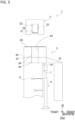
- FIG. 1 is an example of a schematic view of a portion of the spinning winding system 1 according to an embodiment of the present invention, as viewed from a right side.
- FIG. 2 is an example of a schematic view of the portion of the spinning winding system 1 in FIG. 1 , as viewed from a forward side.
- FIGS. 1 and 2 are both views illustrating a state when the spinning winding system 1 is in operation (during production).
- FIG. 3 is an example of a schematic view of a state of the spinning winding system 1 according to an embodiment of the present invention when operation of the spinning winding system 1 is stopped and a cooling unit 5 is lowered.
- spinning of a molten polymer P is stopped.
- a polymer tank 25 and a polymer tube 26 illustrated in FIG. 2 are omitted from the drawings for convenience.
- the spinning winding system 1 is a system for producing thread from a synthetic fiber.
- the spinning winding system 1 includes at least a spinning unit 2, a cooling unit 5, and a moving mechanism 6.
- the spinning winding system 1 may also include an oil application unit 8, a take-back unit (not illustrated), and a take-up unit (not illustrated); however, description of these components is omitted.
- the spinning unit 2 is a melt spinning unit configured to spin the molten polymer P, which is material of a yarn Y.
- the spinning unit 2 includes a generally rectangular-shaped spinning beam 21, a plurality of pack housings 22 formed on the spinning beam 21, a plurality of (e.g., the same number as the number of pack housings 22) spinning packs 23 respectively attached to the plurality of pack housings 22, the polymer tank 25 accommodating a polymer, and a plurality polymer tubes as the polymer tube 26 connecting each of the spinning packs 23 with the polymer tank 25.
- the number of the pack housings 22 and the number of the spinning packs 23 are illustrated as three in FIG. 2 .
- the number of the pack housings 22 and the number of the spinning packs 23 may be larger (e.g., 12).
- the polymer in the polymer tank 25 is sent to the plurality of spinning packs 23 via the plurality of polymer tubes 26.
- a predetermined temperature e.g. 300°C
- Each spinning pack 23 is supplied with liquid molten polymer heated to a high temperature from the polymer tubes 26.
- a spinneret 24 is arranged at a lower end portion of each spinning pack 23.
- the spinneret 24 has, for example, a plurality of nozzles (not illustrated).
- the spinning pack 23 discharges the molten polymer P from each of the plurality of nozzles of the spinneret 24.
- the plurality of molten polymers P discharged from the plurality of nozzles is cooled and solidified at the cooling unit 5 to form a single yarn made up of a plurality of filaments. In other words, one yarn material of one yarn is spun from one spinneret 24.
- each of the spinnerets 24 need not have a plurality of nozzles and may have only one nozzle.
- the cooling unit 5 includes a spinning cylinder 50 arranged below the spinning unit 2, a duct 32 connected to the spinning cylinder 50, and a pressure air source 37 that supplies a cooling air CF to the spinning cylinder 50 via the duct 32.
- an annular yarn cooling unit for example, is used as the cooling unit 5.
- the spinning cylinder 50 is, for example, a hollow box body and has a hollow part 54 extending in an up-and-down direction so as to enclose the molten polymer P spun from the spinneret 24 (so as to allow the molten polymer P to pass through the hollow part 54).
- the spinning cylinder 50 includes a baffle plate 33 therein, and air for cooling supplied from the pressure air source 37 (hereinafter, this air is referred to as "cooling air CF") is supplied through the duct 32 into a lower space of the spinning cylinder 50 (a space lower than the baffle plate 33).
- the cooling air CF that flows into the lower space of the spinning cylinder 50 passes through the baffle plate 33, is caused to flow upward, and flows into an upper space of the spinning cylinder 50 (a space above the baffle plate 33).
- a plurality of partition cylinders 35 are arranged directly below a filter member 36. The partition cylinder 35 is configured such that the cooling air CF is not allowed to pass through the partition cylinder 35 in a radial direction.
- the cooling air CF does not flow directly into the hollow part 54 from the lower space of the spinning cylinder 50.
- the cooling air CF that flows into the upper space of the spinning cylinder 50 is rectified when passing through the filter member 36, which is composed of a perforated filter and a cooling filter, for example, and flows into the hollow part 54.
- the cooling air CF is blown onto the yarn material from the entire outer periphery of the filter member 36 so as to cool the yarn material and form the yarn Y.
- a sealing member 40 is provided at a position where the spinning beam 21 and the spinning cylinder 50 come into contact with each other. This sealing member 40 can prevent leakage from the contact surface between the spinning beam 21 and the spinning cylinder 50.
- the above-described pressure air source 37 corresponds to a "cooling air supply unit" of the present invention.
- the moving mechanism 6 is configured by, for example, an air cylinder (hereinafter, the moving mechanism 6 is referred to as an "air cylinder 6") and is configured to move the cooling unit 5 up and down. More specifically, the air cylinder 6 is erected on the floor of a factory, for example.
- the air cylinder 6 includes a piston rod 7 is arranged such that the piston rod 7 is long in an up-and-down direction and can expand and contract in an up-and-down direction.
- a wall member 10 extending downward is fixed to a lower end of the spinning cylinder 50.
- a distal end portion of the piston rod 7 is fixed to a side face of the wall member 10.
- the cooling unit 5 rises when the piston rod 7 of the air cylinder 6 is actuated in an expanding direction (up direction in FIG. 1 ) and falls when the piston rod 7 is actuated in a contracting direction (down direction in FIG. 1 ).
- the yarn Y can be produced.
- the cooling unit 5 is subjected to an upward force (toward the spinning beam 21) by the air cylinder 6.
- a clearance is formed between the spinning unit 2 (more specifically, the spinning beam 21) and the cooling unit 5 in an up-and-down direction. This clearance serves as a working space.
- a direction toward the first position i.e., an up direction corresponds to "closer to the spinning unit” and a direction toward the second position above, i.e., a down direction corresponds to "away from the spinning unit" in the present invention.
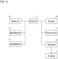
- FIG. 4 is an example of a block diagram schematically illustrating an electrical configuration of the spinning winding system 1.
- a control unit 4 executes processing related to the operation of the spinning winding system 1.
- the control unit 4 performs control of, for example, spinning the molten polymer P from the spinneret 24 and stopping the spinning, actuating or stopping the air cylinder 6, actuating or stopping the pressure air source 37, and controlling the flow rate of the cooling air CF supplied from the pressure air source 37 to the spinning cylinder 50, that is, the hollow part 54.
- the control unit 4 includes a CPU, a ROM and a RAM.
- the control unit 4 is connected to an operation unit 42 configured by operator-operable buttons, etc., an upper end detection sensor 44 that detects that the cooling unit 5 is at the upper end, and a lower end detection sensor 46 that detects that the cooling unit 5 is at the lower end, and other components.
- the control unit 4 can receive signals from, for example, the operation unit 42, the upper end detection sensor 44, and the lower end detection sensor 46.
- the control unit 4 is also connected to a gear pump 28 capable of spinning the molten polymer P from the spinneret 24, the pressure air source 37, and a solenoid valve 48 capable of actuating the air cylinder 6.
- the control unit 4 controls the gear pump 28, the pressure air source 37, and the solenoid valve 48 on the basis of the receipt of various signals from the operation unit 42, the upper end detection sensor 44, and the lower end detection sensor 48.
- the controller 4 controls the operation of the air cylinder 6 by controlling the solenoid valve 48.
- the control unit 4 controls the start of operation and the stop of operation of the pressure air source 37, and also controls the flow rate of the cooling air CF (hereinafter referred to as "air volume”) supplied from the pressure air source 37 to the spinning cylinder 50.
- air volume the cooling air CF supplied from the pressure air source 37 to the spinning cylinder 50.
- control unit 4 controls the air volume of the cooling air CF supplied to the spinning cylinder 50 by controlling the pressure air source 37
- the control unit 4 may control the air volume of the cooling air CF supplied to the spinning cylinder 50 by controlling the opening degree of the automatic valve, for example.
- maintenance is performed periodically. As illustrated in FIG. 3 , maintenance is performed by stopping the spinning of the molten polymer P, actuating the air cylinder 6 in a contracting direction, and lowering the cooling unit 5 with respect to the spinning beam 21.
- the maintenance includes, but is not limited to, cleaning the surface of the spinneret 24 and replacing the spinning pack 23.
- the supply of the cooling air CF from the pressure air source 37 to the spinning cylinder 50 is preferably stopped. This is to prevent the temperature of the spinneret 24 and the temperature around the spinneret 24 from decreasing.
- time is required for the temperature of the spinneret 24 and the temperature around the spinneret 24 to return to the original temperature after maintenance is complete and production is started. Yarn produced in a state where the temperature of the spinneret 24 and the temperature around the spinneret 24 is lowered has lower physical properties, and thus more yarn is discarded. Therefore, to suppress a decrease in the temperature of the spinneret 24 and the temperature around the spinneret 24, the supply of the cooling air CF from the pressure air source 37 to the spinning cylinder 50 is preferably stopped to the extent possible until the cooling unit 5 is raised.
- the spinning of the molten polymer P from the spinneret 24 is started (resumed).
- the operator performs yarn threading work of threading the molten polymer P (or the cooled and solidified yarn Y) spun from the spinneret 24 through the spinning cylinder 50 in a state where the cooling unit 5, that is, the spinning cylinder 50 is lowered with respect to the spinning beam 21.
- the yarn threading work of threading the molten polymer P spun from the spinneret 24 through the hollow part 54 of the spinning cylinder 50 is performed manually by the operator. However, this work is extremely difficult because the molten polymer P is spun continuously from the spinneret 24 and the molten polymer P is hot. Even a skilled worker has difficulty in threading the molten polymer P spun from the spinneret 24 through the hollow part 54 of the spinning cylinder 50, and a large amount of the molten polymer P or cooled and solidified yarn Y may accumulate at the top of the spinning cylinder 50, for example. Furthermore, since the yarn threading work is time-consuming and laborious, the amount of discarded yarn Y increases and the recovery time until the spinning winding system 1 returns to normal operation also increases, which is undesirable from the viewpoint of productivity.
- the spinning winding system 1 of an embodiment of the present invention includes a yarn-threading assist unit 60 (see FIGS. 5 to 7 to be described below) that assists the yarn threading work of threading the molten polymer P through the hollow part 54 of the spinning cylinder 50.
- the yarn-threading assist unit 60 is configured to be attachable and removable to/from the spinning winding system 1, and is removed from the spinning winding system 1 during the operation of the spinning winding system 1 and attached to the cooling unit 5 at least when the yarn threading work to the spinning cylinder 50 is performed.
- FIG. 5 is an example of a schematic perspective view of the cooling unit 5 and the yarn-threading assist unit 60 of components configuring the spinning winding system 1 according to an embodiment of the present invention, as viewed from above.
- FIG. 6 is an example of a schematic perspective view of the cooling unit 5 and the yarn-threading assist unit 60 of the components configuring the spinning winding system 1 according to an embodiment of the present invention, as viewed from below.
- FIGS. 5 and 6 only one yarn-threading assist unit 60 is illustrated for convenience. However, in an embodiment of the present invention, a plurality of yarn-threading assist units 60 are provided. More precisely, one yarn-threading assist unit 60 is provided for one spinning cylinder 50.
- the spinning cylinder 50 includes an inlet portion 52 and an outlet portion 56, and the hollow part 54 between the inlet portion 52 and the outlet portion 56.
- the yarn threading work of threading the yarn into the spinning cylinder 50 is work of threading the molten polymer P through the inlet portion 52 such that the molten polymer P spun from the spinneret 24 (see FIGS. 1 to 3 ) passes through the hollow part 54 and exits the outlet portion 56.
- FIG. 5 for convenience, only one of the plurality of spinning cylinders 50, and the hollow part 54 and the outlet portion 56 are illustrated as dashed lines.
- FIG. 6 for convenience, only one of the plurality of spinning cylinders 50, and the inlet portion 52 and the hollow part 54 are illustrated as dashed lines.
- the yarn-threading assist unit 60 includes a negative pressure generating source 62 and a suction tube 64.
- the negative pressure generating source 62 forms a negative pressure inside the hollow part 54 of the spinning cylinder 50 by suction, for example, and uses a blower actuated (rotated) by a motor as a drive source, for example.
- the negative pressure generating source 62 corresponds to a "negative pressure source" of the present invention.
- the suction tube 64 is, for example, a cylindrical member with a circular opening at an end portion, and connects the outlet portion 56 of the spinning cylinder 50 and the negative pressure generating source 62.
- the suction tube 64 is connected to the negative pressure generating source 62 at one end portion, and an opening 64a at another end portion (hereinafter simply referred to as "opening 64a of the suction tube 64") is connected to the outlet portion 56 of the spinning cylinder 50.
- opening 64a of the suction tube 64 is attached to the cooling unit 5.
- connection between the suction tube 64 and the spinning cylinder 50 (more specifically, the connection between the opening 64a of the suction tube 64 and the outlet portion 56 of the spinning cylinder 50) is achieved by pressing the opening 64a of the suction tube 64 closely against the outlet portion 56 of the spinning cylinder 50.
- the pressing force for pressing the opening 64a against the outlet portion 56 of the spinning cylinder 50 can be as strong as a worker pressing by hand.
- the suction tube 64 described above corresponds to a "tubular portion" of the present invention.
- the diameter of the opening 64a of the suction tube 64 is slightly larger than the diameter of the opening area of the outlet portion 56 of the spinning cylinder 50, so that the suction tube 64 can be inserted over the outlet portion 56. In this way, leakage from the spinning cylinder 50 be prevented, and also the suction tube 64 can be easily pushed against and connected to the outlet portion 56 of the spinning cylinder 50.
- the suction tube 64 and the outlet portion 56 are secured by, for example, a connecting member 72 to prevent the suction tube 64 from detaching from the outlet portion 56.
- a sealing member is preferably provided between an inner peripheral surface of the suction tube 64 and an outer peripheral surface of the outlet portion 56 when the suction tube 64 is inserted over the outlet portion 56.
- the above “opening 64a” corresponds to an "opening area of a portion pressed against the outlet portion of the yarn” of the present invention.
- the above “outlet portion 56 of the spinning cylinder 50” corresponds to an "outlet portion for the yarn” of the present invention.
- the diameter of the opening 64a of the suction tube 64 need not be larger than the diameter of the opening area of the outlet portion 56 of the spinning cylinder 50.
- the diameter of the opening 64a of the suction tube 64 may be smaller than the opening area of the outlet portion 56 of the spinning cylinder 50 provided that the opening 64a of the suction tube 64 can be closely pressed against the outlet portion 56 of the spinning cylinder 50.
- the opening 64a of the suction tube 64 and the outlet portion 56 of the spinning cylinder 50 be completely adhered to each other.
- the opening 64a of the suction tube 64 need not be completely adhered to the outlet portion 56 of the spinning cylinder 50, and the opening 64a and the outlet portion 56 need only be adhered such that the inside of the spinning cylinder 50 (the hollow part 54) has a negative pressure of about 10 kPa (about 10 kPa less than atmospheric pressure).
- a negative pressure of about 10 kPa can be formed inside the spinning cylinder 50 (the hollow part 54), the yarn threading work to the spinning cylinder 50 can be facilitated.
- the method of connecting the suction tube 64 to the outlet portion 56 is not limited to the above-described method as long as the hollow part 54 of the spinning cylinder 50 can be negatively pressurized to generate a flow of air from the inlet portion 52 to the outlet portion 56.
- the suction tube 64 may be inserted into the outlet portion 56 to connect the two, or a lower end portion of the outlet portion 56 and an upper end portion of the suction tube 64 may be made to abut against each other to connect the two.
- the suction tube 64 is preferably flexible and deformable. By making the suction tube 64 flexible and deformable, not only can the connection between the suction tube 64 and the outlet portion 56 of the spinning cylinder 50 and/or the negative pressure generating source 62 be facilitated, but also the route between the outlet portion 56 of the spinning cylinder 50 and the negative pressure generating source 62 can be set as desired.
- the suction tube 64 is provided with a trap portion 70 at the opening 64a on the side connected to the outlet portion 56 of the spinning cylinder 50.
- the trap portion 70 is made of a mesh sheet, for example, that can cover the entire opening 64a.
- the trap portion 70 traps the yarn Y exiting the outlet portion 56 of the spinning cylinder 50, and is preferably a mesh with a smaller mesh opening than the diameter of the yarn Y.
- the location where the trap portion 70 is provided is not limited to the opening 64a of the suction tube 64 on the side connected to the outlet portion 56 of the spinning cylinder 50, and may be any location between the outlet portion 56 and the negative pressure generating source 62.
- the location of the trap portion 70 is not limited to any particular location as long as the yarn Y exiting the outlet portion 56 can be trapped before reaching the negative pressure generating source 62.
- FIG. 7 is an example of a schematic view of a portion of the spinning winding system 1 according to an embodiment of the present invention as viewed from a right side, and illustrates a state in which the yarn-threading assist unit 60 is attached to the cooling unit 5.
- the inside of the spinning cylinder 50 i.e., the hollow part 54
- the inside of the spinning cylinder 50 suctioned by the negative pressure generating source 62 so that a negative pressure is formed inside the spinning cylinder 50.
- a negative pressure is formed inside the hollow part 54 of the spinning cylinder 50
- a flow of air from above to below is generated in the hollow part 54 of the spinning cylinder 50 (see the arrow illustrated in FIG. 7 ). Accordingly, the molten polymer P spun from the spinneret 24 is easily sucked into the interior of the spinning cylinder 50 by simply being brought close to the inlet portion 52 of the spinning cylinder 50.
- FIG. 8 is an example of a schematic perspective view of the cooling unit 5 of the components configuring the spinning winding system 1 according to an embodiment of the present invention, as viewed from above, and illustrates an aspect when yarn threading is performed for the plurality of spinning cylinders 50.
- FIG. 8 is an example of a schematic perspective view of the cooling unit 5 of the components configuring the spinning winding system 1 according to an embodiment of the present invention, as viewed from above, and illustrates an aspect when yarn threading is performed for the plurality of spinning cylinders 50.
- the spinning winding system 1 is configured such that the suction tube 64 is closely pressed against each outlet portion 56 of the plurality of spinning cylinders 50 to connect the two.
- one yarn-threading assist unit 60 can be arranged for each outlet portion 56 of each spinning cylinder 50.
- the hollow part 54 of each of the plurality of spinning cylinders 50 can be reliably pressurized to a negative pressure, enabling efficient yarn threading work to be performed.
- the cooling air CF As described above, it is preferable to stop supplying the cooling air CF (see FIG. 1 ) from the pressure air source 37 (see FIG. 4 ) to the spinning cylinders 50 to the extent possible, especially until the cooling unit 5 is raised.
- the supply of the cooling air CF to the spinning cylinder 50 is stopped, the yarn threading work of threading yarn into the spinning cylinder 50 becomes difficult. Therefore, the supply of the cooling air CF to the spinning cylinder 50 is stopped and a negative pressure is formed inside the spinning cylinder by the yarn-threading assist unit 60 at least when the yarn threading work is performed, so that it is possible to suppress a drop in temperature of the spinneret 24 and temperature of the area surrounding the spinneret 24 and to facilitate the yarn threading work.
- Stopping the supply of the cooling air CF to the spinning cylinder 50 is preferably controlled by the control unit 4 (see FIG. 4 ).
- the operator operates the operation unit 42 (see FIG. 4 ) to stop the operation of the pressure air source 37 (see FIG. 4 ) when performing maintenance.
- the control unit 4 controls the shutdown of the pressure air source 37 on the basis of the operation of the operation unit 42.
- the control unit 4 may control the automatic valve to be closed so that the cooling air CF is not supplied to the spinning cylinder 50.
- the control unit 4 (see FIG. 4 ) is not limited to controlling the air volume of the cooling air CF (see FIG. 1 ) supplied to the spinning cylinder 50 on the basis of the operation of the operation unit 42 (see FIG. 4 ).
- the control unit 4 may stop supply of the cooling air CF to the spinning cylinder 50 when the upper end detection sensor 44 (see FIG. 4 ) is not detected (i.e., when the spinning cylinder 50 is not at the upper end).
- the controller 4 may stop supply of the cooling air CF to the spinning cylinder 50 when the lower end detection sensor 46 (see FIG. 4 ) is detected (i.e., when the spinning cylinder 50 is at the lower end).
- control unit 4 may stop supply of the cooling air CF to the spinning cylinder 50 when the spinning cylinder 50 is between the upper end and the lower end in an up-and-down direction, such as when neither the upper end detection sensor 44 nor the lower end detection sensor 46 is detected, or when another detection sensor is installed between the upper end detection sensor 44 and the lower end detection sensor 46 and this sensor is detected.
- the supply of the cooling air CF (see FIG. 1 ) to the spinning cylinder 50 is preferably stopped when the yarn threading work of threading the yarn through the spinning cylinder 50 is performed, but it is not necessary to stop the cooling air CF completely.
- the present invention does not exclude a configuration where a small air volume (e.g. , a minute air volume) as compared to when the spinning winding system 1 is operating is supplied to the spinning cylinder 50, provided that it is possible to suppress a drop in temperature of the spinneret 24 and the area around the spinneret 24.
- the spinning winding system 1 according to the present invention is as described in the above-mentioned embodiment, but the spinning winding system according to the present invention is not limited to the spinning winding system 1 described above.
- First and second modified examples are described below. Note that, in the first and second modified examples to be described below, description will focus on configurations that differ from that of an embodiment of the present invention described above, and other configurations will be omitted from the description to the extent possible.
- common reference signs shall be used for configurations that are common to the various configurations in the spinning winding system 1 of an embodiment of the present invention described above.
- one yarn-threading assist unit 60 is provided for each spinning cylinder 50.
- the number of yarn-threading assist units is less than the number of spinning cylinders 50.
- a spinning winding system 1A according to the first modified example is described below.
- the spinning winding system 1A includes a yarn-threading assist unit 60A instead of the yarn-threading assist unit 60 included in the spinning winding system 1.
- the various configurations of the spinning winding system 1A are the same as those of the spinning winding system 1, except for the yarn-threading assist unit 60A.
- FIG. 9 is an example of a schematic perspective view of a cooling unit 5 and the yarn-threading assist unit 60A of the spinning winding system 1A according to the first modified example, as viewed from below.
- FIG. 9 for convenience, only one of the plurality of spinning cylinders 50, an inlet portion 52 and a hollow part 54 are illustrated with dashed lines.
- the spinning winding system 1A includes, for example, one yarn-threading assist unit 60A as a number smaller than the number of the plurality of spinning cylinders 50.
- the yarn-threading assist unit 60A includes, for example, one negative pressure generating source 62A and a suction tube 64A. Similar to the negative pressure generating source 62 in the yarn-threading assist unit 60, the negative pressure generating source 62A forms a negative pressure inside the hollow part 54 of the spinning cylinder 50 by using, for example, a blower actuated (rotated) by a motor as a drive source. However, the suction force of the negative pressure generating source 62A is preferably greater than that of the negative pressure generating source 62.
- the suction tube 64A includes, for example, one merge tube 641A connected to the negative pressure generating source 62A and a plurality of branch tubes 642A connected to the merge tube 641A.
- the merge tube 641A is connected to the negative pressure generating source 62A.
- the plurality of branch tubes 642A are each connected to the merge tube 641A at one end.
- the number of branch tubes 642A is the same as the number of spinning cylinders 50, and the branch tubes 642A are each configured such that the other end of each branch tube 642A can be connected to the outlet portion 56 of a corresponding spinning cylinder 50.
- the branch tube 642A also corresponds to the "tubular portion" of the present invention.
- the plurality of branch tubes 642A each have a diameter slightly larger than the diameter of the corresponding outlet portion 56 such that they can be inserted over the outlet portion 56 of the corresponding (connected) spinning cylinder 50.
- the branch tubes 642A and the outlet portion 56 are secured to each other by, for example, a connecting member 72, to prevent the branch tube 642A from detaching from the outlet portion 56.
- a sealing member is preferably provided between an inner peripheral surface of the branch tube 642A and an outer peripheral surface of the outlet portion 56 when the branch tube 642A is inserted over the outlet portion 56.
- the hollow parts 54 of the spinning cylinders 50 can be negatively pressurized.
- the plurality of branch tubes 642A are preferably flexible and deformable, similar to the suction tube 64.
- the number of yarn-threading assist units 60A can be reduced and the yarn threading work can be facilitated while suppressing the installation space required for the yarn-threading assist units 60A.
- the burden of connecting the yarn-threading assist units 60A to the plurality of spinning cylinders 50 can be reduced, thereby shortening work time.
- one yarn-threading assist unit 60A (more precisely, one negative pressure generating source 62A) is provided for a plurality of spinning cylinders 50.
- the number of yarn-threading assist units 60A provided in the spinning winding system 1A is not limited to one.
- the number of yarn-threading assist units 60A included in the spinning winding system 1A is two.
- the suction tube 64 or the branch tube 642A is connected to the outlet portion 56 of the corresponding spinning cylinder 50.
- the suction tube 64 or the branch tube 642A is connected to the cooling unit 5.
- a spinning winding system 1B according to the second modified example is described below.
- the spinning winding system 1B includes a yarn-threading assist unit 60B in place of the yarn-threading assist unit 60 in the spinning winding system 1.
- the various configurations of the spinning winding system 1B are the same as those of the spinning winding system 1, except for the yarn-threading assist unit 60B.
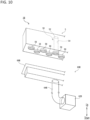
- FIG. 10 is an example of a schematic perspective view of a cooling unit 5 and the yarn-threading assist unit 60B of the spinning winding system 1B according to the second modified example, as viewed from below.
- FIG. 10 for convenience, only one of the plurality of spinning cylinders 50, the inlet portion 52 and the hollow part 54 are illustrated with dashed lines.
- the yarn-threading assist unit 60B includes, for example, a negative pressure generating source 62B, a suction tube 64B, and a box-shaped cover member 66B. Similar to the negative pressure generating source 62 in the yarn-threading assist unit 60, the negative pressure generating source 62B forms a negative pressure inside the hollow part 54 of the spinning cylinder 50 by using, for example, a blower actuated (rotated) by a motor as a drive source. However, the suction force of the negative pressure generating source 62B is preferably greater than that of the negative pressure generating source 62.
- the suction tube 64B has one end portion connected to the negative pressure generating source 62B and the other end portion connected to the cover member 66B.
- the cover member 66B is configured to be closely pressed against a lower surface of the cooling unit 5, for example, so that the two can be connected.
- the cover member 66B is connected to the cooling unit 5, the outlet portions 56 of the plurality of spinning cylinders 50 are covered by the cover member 66B.
- the negative pressure generating source 62B When the negative pressure generating source 62B is actuated in a state where the cover member 66B is connected to the cooling unit 5, the inside of the cover member 66B and thus the hollow part 54 of the spinning cylinder 50 is suctioned by the negative pressure generating source 62B so that a negative pressure is formed inside the spinning cylinder 50.
- a flow of air from above to below is generated in the hollow part 54 of the spinning cylinder 50, and the molten polymer P spun from the spinneret 24 is easily sucked into the interior of the spinning cylinder 50 by simply being brought close to the inlet portion 52 of the spinning cylinder 50.
- one yarn-threading assist unit 60 is provided for each spinning cylinder 50.
- fewer yarn-threading assist units 60A than the number of spinning cylinders 50 are provided.
- the yarn -threading assist unit 60B (more particularly, the suction tube 64 or the branch tube 642A) is configured to be connected to the cooling unit 5. All of the yarn-threading assist units 60, 60A, and 60B described above are provided for one spinning winding system 1, but no limitation is intended.
- a yarn-threading assist unit 60C according to a third modified example will be described below with reference to FIG. 11 .
- FIG. 11 is a schematic view of the yarn-threading assist unit 60C according to the third modified example, illustrating a portion of a spinning winding system 1C from a forward side.
- the spinning winding system 1C includes a plurality of spinning units 2C, a plurality of cooling units 5C, a plurality of moving mechanisms (not illustrated), and one yarn-threading assist unit 60C.
- the plurality of spinning units 2C, the plurality of cooling units 5C, and the plurality of moving mechanisms are arranged in a left-and-right direction illustrated in FIG. 11 .
- two spinning units 2C and two cooling units 5C are illustrated in FIG. 11 , but this is not intended to exclude three or more spinning units 2C or cooling units 5C from being arranged in a left-and-right direction.
- suction tubes and other components included in the yarn-threading assist unit 60C are omitted.
- the spinning winding system 1C is partitioned into a lower floor (e.g., first floor) and an upper floor (e.g., second floor) by a partition floor 100. At least a plurality of spinning units as the spinning unit 2C, a plurality of cooling units as the cooling unit 5C, and one yarn-threading assist unit 60C are arranged on the upper floor. With this configuration, the spinning winding system 1C can take in, at the lower floor, yarn spun from the spinning units 2C provided on the upper floor and cooled by the cooling units 5C.
- the partition floor 100 includes a plurality of apertures 80 formed in a left-and-right direction of the paper in FIG. 11 , through which a plurality of yarns as the yarn Y spun from each of the spinning units 2C arranged on the upper floor can pass.
- a cylindrical cover member 82 protruding downward from the partition floor 100 is installed to prevent yarn swaying and the like.
- a tubular fall prevention wall 84 protruding upward from the partition floor 100 is installed to prevent the yarn-threading assist unit 60C and other components from falling from the upper floor.
- the yarn-threading assist unit 60C includes wheels and can move freely on the upper floor.
- the yarn-threading assist unit 60C may be placed on a cart so that the yarn-threading assist unit 60C can move freely on the upper floor, or rails may be provided on the upper floor so that the yarn-threading assist unit 60C can move freely on the upper floor.
- no limitation is intended as long as the yarn-threading assist unit 60C can be freely moved around the upper floor so that the yarn-threading assist unit 60C can be attached to and detached from any of the plurality of spinning cylinders 50C of the plurality of cooling units 5C arranged on the upper floor.
- the yarn-threading assist unit 60C can be attached to and detached from the spinning cylinder 50C of the cooling unit 5C after the cooling unit 5C is lowered by the moving mechanisms.
- the yarn-threading assist unit 60C may have the same configuration as any of the yarn-threading assist units 60 described in an embodiment of the present invention above, the yarn-threading assist unit 60A described in the first modified example, and the yarn-threading assist unit 60B described in the second modified example, or may have a different configuration from these.
- the number of yarn-threading assist units 60C provided may be one yarn-threading assist unit 60C for two spinning units 2C, two cooling units 5C, and two moving mechanisms (not illustrated), or one yarn-threading assist unit 60C for five spinning units 2C, five cooling units 5C, and five moving mechanisms (not illustrated).
- the number of yarn-threading assist units 60C need only be less than the number of spinning units 2C, the number of cooling units 5C, and the number of moving mechanisms.
- the number of spinning units 2C, cooling units 5C, and moving mechanisms may be any number, and may be 10 or more, for example.
- the yarn-threading assist unit 60C according to the third modified example can be attached to or detached from any of the plurality of spinning cylinders 50C of the plurality of cooling units 5C by moving freely on the upper floor. Therefore, a negative pressure can be formed inside the spinning cylinder 50C ( i.e., the hollow part 54C) in the cooling unit 5C corresponding to any spinning unit 2C among the plurality of spinning units 2C (e.g., the spinning unit 2C to be maintained), enabling efficient yarn threading work.
- the method by which the suction tube 64 or the suction tube 64A is closely pressed against the outlet portion 56 of the spinning cylinder 50 to connect the two as described in an embodiment of the present invention and the first modified example, and the method by which the cover member 66B is closely pressed against the cooling unit 5 to connect the two as described in the second modified example both correspond to "arranged so as to be pressed against the outlet portion for the yarn" in the present invention.
- the "outlet portion for the yarn” does not mean only the outlet portion 56 of the spinning cylinder 50 and may be any portion, such as below the cooling unit 5, as long as the hollow part 54 of the spinning cylinder 50 can be negatively pressurized to generate a flow of air from above to below.
Landscapes
- Engineering & Computer Science (AREA)
- Mechanical Engineering (AREA)
- Textile Engineering (AREA)
- Spinning Methods And Devices For Manufacturing Artificial Fibers (AREA)
- Yarns And Mechanical Finishing Of Yarns Or Ropes (AREA)
Applications Claiming Priority (1)
| Application Number | Priority Date | Filing Date | Title |
|---|---|---|---|
| JP2023083855 | 2023-05-22 |
Publications (2)
| Publication Number | Publication Date |
|---|---|
| EP4471192A2 true EP4471192A2 (fr) | 2024-12-04 |
| EP4471192A3 EP4471192A3 (fr) | 2025-03-12 |
Family
ID=91185046
Family Applications (1)
| Application Number | Title | Priority Date | Filing Date |
|---|---|---|---|
| EP24176707.8A Pending EP4471192A3 (fr) | 2023-05-22 | 2024-05-17 | Système d'enroulement de filage et unité d'assistance au filetage de fil |
Country Status (3)
| Country | Link |
|---|---|
| EP (1) | EP4471192A3 (fr) |
| JP (1) | JP2024167890A (fr) |
| CN (1) | CN118996646A (fr) |
Citations (1)
| Publication number | Priority date | Publication date | Assignee | Title |
|---|---|---|---|---|
| JP2005042227A (ja) | 2003-07-24 | 2005-02-17 | Tmt Machinery Inc | 溶融紡糸装置 |
Family Cites Families (6)
| Publication number | Priority date | Publication date | Assignee | Title |
|---|---|---|---|---|
| JPH06158416A (ja) * | 1992-11-19 | 1994-06-07 | Toray Ind Inc | 紡糸装置 |
| JPH07101630A (ja) * | 1993-10-08 | 1995-04-18 | Teijin Ltd | 断糸処理装置及び断糸処理方法 |
| DE19544662A1 (de) * | 1995-11-30 | 1997-06-05 | Rieter Automatik Gmbh | Schmelzespinnvorrichtung |
| WO2000005439A1 (fr) * | 1998-07-23 | 2000-02-03 | Barmag Ag | Dispositif et procede permettant de filer un fil synthetique |
| JP2002317326A (ja) * | 2001-04-18 | 2002-10-31 | Teijin Ltd | 溶融紡糸装置 |
| JP7698989B2 (ja) * | 2021-06-10 | 2025-06-26 | Tmtマシナリー株式会社 | 紡糸引取装置 |
-
2024
- 2024-05-07 CN CN202410552814.XA patent/CN118996646A/zh active Pending
- 2024-05-10 JP JP2024077387A patent/JP2024167890A/ja active Pending
- 2024-05-17 EP EP24176707.8A patent/EP4471192A3/fr active Pending
Patent Citations (1)
| Publication number | Priority date | Publication date | Assignee | Title |
|---|---|---|---|---|
| JP2005042227A (ja) | 2003-07-24 | 2005-02-17 | Tmt Machinery Inc | 溶融紡糸装置 |
Also Published As
| Publication number | Publication date |
|---|---|
| JP2024167890A (ja) | 2024-12-04 |
| CN118996646A (zh) | 2024-11-22 |
| EP4471192A3 (fr) | 2025-03-12 |
Similar Documents
| Publication | Publication Date | Title |
|---|---|---|
| US9353463B2 (en) | Spinning point of a spinning machine and method for the operation of the same | |
| CN106414819B (zh) | 纺丝牵引装置 | |
| US11873581B2 (en) | Method and device for cleaning spinnerets while producing cellulose spunbonded nonwoven fabric | |
| CN104911755A (zh) | 纺纱机和将纱线传送至接纱装置的方法 | |
| EP4471192A2 (fr) | Système d'enroulement de filage et unité d'assistance au filetage de fil | |
| US20180112334A1 (en) | Work Station of a Textile Machine, Pneumatic Thread Storage Element for a Work Station of a Textile Machine and a Textile Machine | |
| KR101329210B1 (ko) | 스플라이서 장치의 클리너 장치 | |
| EP3388563B1 (fr) | Métier à filer | |
| CN104911753A (zh) | 自动卷层拼接设备 | |
| JP7374771B2 (ja) | 合成糸を溶融紡糸するための方法および装置 | |
| EP2796616A1 (fr) | Système de nettoyage pour appareil à sténopé | |
| JP7773880B2 (ja) | 紡糸設備、及び紡糸巻取設備 | |
| CN104213279B (zh) | 纺纱机的气动装置 | |
| EP4234775B1 (fr) | Système de filage et méthode de contrôle d'un système de filage | |
| CN109137162B (zh) | 空气纺纱机 | |
| EP4234776A1 (fr) | Système de filage et méthode de contrôle d'un système de filage | |
| EP3103903B1 (fr) | Métier à filer et procédé de filage | |
| JP2005041673A (ja) | 断糸処理装置 | |
| EP4361075A1 (fr) | Dispositif de fixation de fil et équipement de filage et de traitement | |
| JP2001131822A (ja) | 糸条処理装置および糸条製造設備 | |
| JPH0635685B2 (ja) | 溶融紡糸装置 | |
| JPH10282347A (ja) | 光ファイバの線引きスタート補助駆動装置 | |
| KR102351807B1 (ko) | 교환 가능한 스핀빔 | |
| CN113195817A (zh) | 用于在制造纤维素纺黏型非织造织物时回收利用溶剂和纤维素的方法 | |
| ES2384217T3 (es) | Dispositivo de limpieza para máquinas tejedoras |
Legal Events
| Date | Code | Title | Description |
|---|---|---|---|
| PUAI | Public reference made under article 153(3) epc to a published international application that has entered the european phase |
Free format text: ORIGINAL CODE: 0009012 |
|
| STAA | Information on the status of an ep patent application or granted ep patent |
Free format text: STATUS: THE APPLICATION HAS BEEN PUBLISHED |
|
| AK | Designated contracting states |
Kind code of ref document: A2 Designated state(s): AL AT BE BG CH CY CZ DE DK EE ES FI FR GB GR HR HU IE IS IT LI LT LU LV MC ME MK MT NL NO PL PT RO RS SE SI SK SM TR |
|
| PUAL | Search report despatched |
Free format text: ORIGINAL CODE: 0009013 |
|
| AK | Designated contracting states |
Kind code of ref document: A3 Designated state(s): AL AT BE BG CH CY CZ DE DK EE ES FI FR GB GR HR HU IE IS IT LI LT LU LV MC ME MK MT NL NO PL PT RO RS SE SI SK SM TR |
|
| RIC1 | Information provided on ipc code assigned before grant |
Ipc: D01D 5/088 20060101ALI20250205BHEP Ipc: D01D 5/092 20060101ALI20250205BHEP Ipc: D02G 1/02 20060101ALI20250205BHEP Ipc: D01D 7/00 20060101ALI20250205BHEP Ipc: B65H 57/00 20060101ALI20250205BHEP Ipc: D01D 13/02 20060101ALI20250205BHEP Ipc: D01D 5/08 20060101AFI20250205BHEP |
|
| STAA | Information on the status of an ep patent application or granted ep patent |
Free format text: STATUS: REQUEST FOR EXAMINATION WAS MADE |
|
| 17P | Request for examination filed |
Effective date: 20250912 |