EP4234973A2 - Engrenage avec moyen de traction - Google Patents
Engrenage avec moyen de traction Download PDFInfo
- Publication number
- EP4234973A2 EP4234973A2 EP23179082.5A EP23179082A EP4234973A2 EP 4234973 A2 EP4234973 A2 EP 4234973A2 EP 23179082 A EP23179082 A EP 23179082A EP 4234973 A2 EP4234973 A2 EP 4234973A2
- Authority
- EP
- European Patent Office
- Prior art keywords
- der
- und
- wobei
- die
- pinring
- Prior art date
- Legal status (The legal status is an assumption and is not a legal conclusion. Google has not performed a legal analysis and makes no representation as to the accuracy of the status listed.)
- Pending
Links
Images


Classifications
-
- F—MECHANICAL ENGINEERING; LIGHTING; HEATING; WEAPONS; BLASTING
- F16—ENGINEERING ELEMENTS AND UNITS; GENERAL MEASURES FOR PRODUCING AND MAINTAINING EFFECTIVE FUNCTIONING OF MACHINES OR INSTALLATIONS; THERMAL INSULATION IN GENERAL
- F16G—BELTS, CABLES, OR ROPES, PREDOMINANTLY USED FOR DRIVING PURPOSES; CHAINS; FITTINGS PREDOMINANTLY USED THEREFOR
- F16G1/00—Driving-belts
- F16G1/28—Driving-belts with a contact surface of special shape, e.g. toothed
-
- F—MECHANICAL ENGINEERING; LIGHTING; HEATING; WEAPONS; BLASTING
- F16—ENGINEERING ELEMENTS AND UNITS; GENERAL MEASURES FOR PRODUCING AND MAINTAINING EFFECTIVE FUNCTIONING OF MACHINES OR INSTALLATIONS; THERMAL INSULATION IN GENERAL
- F16H—GEARING
- F16H49/00—Other gearings
- F16H49/001—Wave gearings, e.g. harmonic drive transmissions
-
- B—PERFORMING OPERATIONS; TRANSPORTING
- B62—LAND VEHICLES FOR TRAVELLING OTHERWISE THAN ON RAILS
- B62M—RIDER PROPULSION OF WHEELED VEHICLES OR SLEDGES; POWERED PROPULSION OF SLEDGES OR SINGLE-TRACK CYCLES; TRANSMISSIONS SPECIALLY ADAPTED FOR SUCH VEHICLES
- B62M9/00—Transmissions characterised by use of an endless chain, belt, or the like
-
- F—MECHANICAL ENGINEERING; LIGHTING; HEATING; WEAPONS; BLASTING
- F16—ENGINEERING ELEMENTS AND UNITS; GENERAL MEASURES FOR PRODUCING AND MAINTAINING EFFECTIVE FUNCTIONING OF MACHINES OR INSTALLATIONS; THERMAL INSULATION IN GENERAL
- F16H—GEARING
- F16H49/00—Other gearings
- F16H49/001—Wave gearings, e.g. harmonic drive transmissions
- F16H2049/003—Features of the flexsplines therefor
Definitions
- a central bearing area on the inside of a toothed belt corresponds to the “inner bearing surface” of a pin ring, in particular a one-piece pin ring, and a central bearing area on the outside of a toothed belt corresponds to an “outer bearing surface” of a pin ring, in particular a one-piece pin ring.
- a “rotor-transmitter unit” corresponds to an inner rotor shaft 27 and a cam disk 28 or an inner rotor shaft 27 and an eccentric disk 28'
- an “inner wheel output shaft unit” corresponds to an inner wheel 7 with a hollow shaft area 234.
- An “outer wheel assembly” corresponds to a support ring 36 having a first outer wheel 8 attached thereto or inserted therein and a second outer wheel 8 ′ attached thereto or inserted therein.
- a "one-epicycle gearing” corresponds to a gearing based on a wheel curve with an epicycle, as is also defined, for example, in item 1 of the first list at the end of the present description.
- a “two-epicycle gearing” corresponds to a gearing based on an epicycle wheel curve with two epicycles, such as those also described in bullet points 12 or 13 of the first listing at the end of the present description.
- the present description discloses a toothed belt with an internal tooth system and an external tooth system, with tooth tips of the internal tooth system having a rounded area with a cross section in the shape of a segment of a circle. Tooth tips of the external toothing have a rounded area with a cross section in the shape of a segment of a circle. An area between two adjacent tips of the internal teeth is at least as wide as a tooth width of teeth of the internal teeth, and an area between two adjacent tips of the external teeth is at least as wide as a tooth width of teeth of the external teeth.
- the area between the tooth tips can be at least as wide as a width of the tooth tips of the respective toothing plus a width that is determined by the shape of a toothing of an outer wheel or an inner wheel of a transmission that matches the respective toothing of the toothed ring.
- tooth tips of the internal toothing can be arranged radially opposite the tooth tips of the external toothing according to a symmetrical arrangement.
- tooth tips of the internal toothing can be arranged in a staggered arrangement radially opposite tooth roots of the external toothing.
- tooth bases of the internal toothing can be formed as flat tooth bases which correspond to a section of a vertical circular cylinder. This shape allows for simple manufacture, for example by forming from a cylindrical workpiece and is suitably designed Counter-toothing of an inner or outer wheel that engages in the toothed belt is sufficient to achieve good to very good engagement of the toothed belt.
- the toothed belt is in the form of a corrugated sheet in the form of a vertical circular cylinder which has a constant thickness, the internal toothing being formed by a rear side of the external toothing, and the external toothing being formed by a rear side of the internal toothing.
- an inner side of the toothed belt has a smooth, central support area, which is designed in the form of a vertical circular cylinder, so that the internal toothing adjoins the central support area at axially opposite areas. What is meant here is smooth compared to a unaided observable scale, rather than on a microscopic scale.
- an outside of the toothed belt can have a central support area, which is designed in the form of a vertical circular cylinder, so that the external toothing adjoins the central support area at axially opposite areas.
- the toothed belt can be manufactured from one piece, for example cast, milled or stamped, which allows efficient manufacture and good stability.
- the toothed belt comprises plastic, with it comprising more than 90 percent by weight plastic can or can be made entirely of plastic.
- the toothed belt has a steel alloy, in which case it can have more than 90 percent by weight steel alloy or can also be made entirely of a steel alloy.
- the toothed belt can comprise a steel-cobalt-manganese alloy, comprise more than 90 percent by weight of a steel-cobalt-manganese alloy, or be made entirely of a steel-cobalt-manganese alloy.
- the present description discloses a transmission with an input shaft and an output shaft, with an outer wheel and an inner wheel arranged concentrically to the outer wheel inside the outer wheel, and with a traction mechanism extending between the outer wheel and the inner wheel.
- the transmission has at least one revolving transmitter, which lifts the traction mechanism from the outer circumference of the inner wheel and presses it against the inner circumference of the outer wheel.
- the traction means is designed as the toothed belt according to the above description.
- the input shaft may be connected to the transmitter, the outer gear, or the inner gear
- the output shaft may be connected to the transmitter, the outer gear, or the inner gear if the input shaft is not already connected thereto.
- the present description discloses a transmission according to one of the bullet points 1, 15, 34, 37, 46, 52, 57 or 59 of the second bullet point of the present description, wherein the traction mechanism is designed as the aforementioned toothed belt.
- the present description discloses a harmonic pin ring gear according to bullet point 1 of the first bullet point of the present description, the pin ring being designed as the toothed belt mentioned above.
- the present description discloses a harmonic pin ring gear according to bullet point 14 of the first bullet point of the present description, the pin ring being designed as the toothed belt mentioned above.
- an electric motor can be provided, the rotor of which is connected to the input shaft of the transmission.
- an internal combustion engine can also be provided, with an output shaft of the internal combustion engine being connected to the input shaft of the transmission.
- the present description discloses a vehicle, in particular a two-wheeler or three-wheeler, with the above-mentioned motor-gear unit, wherein at least one running wheel of the vehicle is connected to the output shaft of the gear.
- the present description discloses a power generator with a drive unit, with a generator unit for generating power and with a transmission mentioned above, wherein an input shaft of the transmission is connected to the drive unit and wherein an output shaft of the Transmission is connected to an input shaft of the generator.
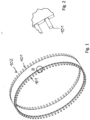
- FIG. 1 shows a perspective view of a first embodiment of a pin ring 201 with a gap arrangement of the pins 101.
- an intermediate space is arranged between two pins or teeth that is at least as wide as the width of the pins or teeth .
- the extent of a tooth in the circumferential direction halfway between the tooth base and the tooth crest can be regarded as the tooth width, for example.
- the tooth width corresponds to the width at the level of a pitch circle.
- a pin or a tooth of a traction mechanism alternately engages in a tooth base of the respective external or internal toothing of the transmission, and a tooth base that is adjacent in the circumferential direction is not engaged.
- the teeth or pins are preferably designed in such a way that all pins or teeth of a traction means are in contact or engaged with an opposite tooth of the respective internal or external toothing, so that the engagement area extends over the entire circumference or over 360 degrees extends as it is in 18 is shown. In a broader sense, this is also referred to as engagement when two opposing tooth tips rest on one another, as is the case in the middle of 18 is shown for the external gearing.
- FIG 2 shows an enlarged detail of the pin ring 102 from FIG 1 , in which a transition area between the pins 101 and a central support ring is shown.
- the pin ring is made of one piece.
- the laterally protruding pins can be milled or punched out of a workpiece.
- a steel alloy is suitable, for example, which is characterized by good stampability and formability.
- this can be a manganese-chromium steel alloy such as 16MnCr5, material number 1.7131.
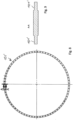
- 3 12 shows a side view of the pin ring 102 of FIG 1 , in which an angular distance between the pins is drawn. This angular distance depends on a radius of the pin ring and on a number of pins distributed evenly over the circumference and is 4.8 degrees in the example of 3 .
- FIG 4 shows a cross section of the pin ring 102 along the section line AA of FIG 3 .
- a diameter of the pins can be seen to be approximately as large as a thickness of the central support ring.
- figure 5 10 shows a front view of the pin ring 102 of FIG 1 , in which the central support ring and the pins, which project to the right and left of the central support ring in the axial direction, are shown.
- FIG 6 shows a perspective view of a second embodiment of a pin ring 102' with a gap arrangement of the pins 101'.
- This embodiment differs from the embodiment of FIG 1 in that the diameter of the pins is less than a thickness of the central support ring
- FIG 7 10 shows a front view of the pin ring 102' of FIG 6 .
- 9 12 shows a cross-sectional view of the pin ring 102' of FIG 6 along the section line AA of 8 .
- the pin ring 102' is manufactured in such a way that the diameter of the workpiece tapers outwards in the axial direction in a transition area to a diameter of the pins which here is approximately two thirds of the thickness of the central support ring.
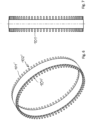
- the Figures 10 to 13 , 15 and 17 show pin rings which are designed in the manner of a toothed belt and have external teeth and internal teeth, with the number of teeth on the external toothing corresponding to the number of teeth on the internal toothing.
- the teeth can also be viewed as pins and the pin rings of Figures 10 to 13 , 15 and 17 are also referred to as double pin rings or double toothed rings.
- the pinrings of Figures 10 - 17 can be made of an elastic material and/or suitably dimensioned so that they are particularly suitable for an oval or ellipsoidal deformation, with the location of the deformation rotating on a circular path due to a rotating transmitter arranged radially inside the respective pin ring.
- the pinrings of Figures 10 - 17 can also be made of an inelastic or less elastic material and/or be dimensioned accordingly, so that they are suitable for being guided on a circular path by an eccentrically arranged cylindrical cam disk of a transmitter.
- the cross section of the teeth can resemble a cross section of half a pin, that is to say it can be approximately semicircular or, apart from a transition area, can be in the shape of a segment of a circle. At least the upper area of the tooth tips is preferably rounded off in the shape of a segment of a circle.
- This upper area which is rounded off in the shape of a segment of a circle, can, for example, extend over at least 30% or at least 40% of a tooth height measured from the center between the tooth base and the tooth tip, as seen from the tooth tip, which on the one hand allows a larger transition area between the tooth tip and tooth base to be made available and on the other hand the tooth shape is still sufficiently similar to a pin shape.
- Elasticity can be provided by the transition area and there is freedom of design to adapt the dimensioning of the tooth geometry of the toothed belt to an external toothing of an internal wheel or to an internal toothing of an external wheel.
- the rounded upper area in the form of a segment of a circle can extend over at least 70%, at least 80% or at least 90% of a tooth height measured from the center between the tooth base and the tooth tip, as seen from the tooth tip, as a result of which the best possible similarity to a pin shape is achieved. Due to the similarity of the tooth shape with the pin shape, for example, the best possible engagement with the one-epicycle toothing disclosed in PCT/IB2017/057452 or the two-epicycle toothing of an outer wheel and/or an inner wheel also disclosed there can be achieved.
- the rounded upper area in the form of a segment of a circle can extend over at least 50%, at least 60% of the tooth height measured from the middle between the tooth base and the tooth tip, as seen from the tooth tip, whereby a compromise between a pin-like tooth shape and a sufficiently wide transition area is achieved .
- the tooth base of the internal toothing and the external toothing can be flat, i.e. form a section of a cylinder, as is shown, for example, in Figures 10 to 13 is shown.
- the tooth shape of the internal toothing can match or be structurally identical to the tooth shape of the external toothing.
- the tooth shape of the internal and external toothing preferably corresponds to a straight tooth shape or a tooth shape of a spur gear, which can be easily produced, for example, by milling.
- a helical gearing, not shown in the figures, is also possible.
- the double toothed rings can have, among other things, a one-epicycle toothing or a two-epicycle toothing, as described in PCT/IB2017/057452.
- FIG. 10 shows a perspective view of a pin ring 102'' or toothed belt 102'' with a staggered gap arrangement, the pins or teeth of an internal toothing 106 and an external toothing 105 being offset from one another. Specifically, a tooth or pin of the external toothing 105 is opposite a tooth base or pin of the internal toothing 106 .
- FIG. 11 shows a perspective view of a further pin ring 102''' with a staggered gap arrangement with central support areas 107, 108 on the inside and outside, with an inner toothing 105' being offset relative to an outer toothing 106'.
- 12 12 shows a perspective view of another pin ring 102 (IV) with an offset gap arrangement with a central bearing area 107 on the inside, with an internal toothing 105'' being offset with respect to an external toothing 106''.
- the central contact area 107 on the inside can be used in particular to provide improved contact with a cam disk or an outer surface of a transmitter
- the central contact area 108 on the outside can be used in particular to create improved contact with a cylindrical contact surface of a transmission housing, which facing the outer surface of the transmitter.
- external teeth matching the internal teeth of the toothed belt can be arranged radially inside the toothed belt for improved support of a transmitter.
- this external toothing can be arranged on a ball bearing, whereas in the case of a static internal wheel which has not been driven off, this external toothing can be fastened to a transmission housing.
- external teeth matching the external teeth of the toothed belt can be arranged radially outside of the toothed belt for improved support.
- this external toothing can be arranged on a ball bearing, whereas in a transmission with a non-aborted, static external wheel, as in the transmission of FIG Figures 18 - 20 , Can be attached to a transmission housing.
- external wheel teeth can also extend over the entire width of the toothed belt, which also achieves good contact.
- FIG. 13 shows a perspective view of another pin ring 102 (V) with a symmetrical gap arrangement, in which the teeth or pins of an internal toothing 106′′′ and an external toothing 105′′′ face each other.
- a central support area can be provided on an inside of the toothed belt or on an outside of the toothed belt.
- FIG. 14 shows a perspective view of a further pin ring 102 (VI) with a symmetrical gap arrangement, in which radial gaps are arranged between pins 101'''.
- pins 101 ′′′ When pinring by 14 are the pins 101 ′′′ shaped so that their cross section forms an elongated oval, which is particularly good in the detail enlargement of 16 can be seen. Namely, the cross section of the pins forms 101'' Rectangle with two semi-circular ends on the narrower sides of the rectangle, where the semi-circular ends can be the same.
- FIG. 15 shows a perspective view of a further pin ring 102 (VII) or toothed belt or double toothed ring 102 (VII) , in which the tooth bases each form the tooth tips of the radially opposite toothing.
- a rear side of an external toothing 105 (IV) simultaneously forms an internal toothing 106 (IV) and vice versa.
- the shape of the double toothed ring resembles a cylindrical strip of corrugated iron, which works particularly well in the detail enlargement of 17 is recognizable.
- the design of the double toothed ring according to 15 can provide good elasticity with simple and material-saving manufacture.
- 16 shows an enlargement of 14 .
- 17 shows an enlargement of 15 .
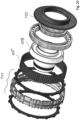
- FIG. 18 shows an output-side front view of a harmonic pin ring gear with an oval cam disc, in which a pin ring 102" according to 10 is installed as traction means, and in which, from the inside to the outside, an inner region of a rotor-transmitter unit 109 of an internal rotor motor (not shown), an inner wheel output shaft unit 110, a pin ring 102" according to 10 and an outer wheel assembly 111 are shown.
- FIG 19 shows a cross-section along line AA of FIG 18 .
- the inner wheel output shaft unit 110 is mounted on the rotor transmitter unit via an output shaft ball bearing.
- a deformable ball bearing is mounted on a cam disk of the rotor-transmitter unit 109 and the pin ring according to figure 12 is placed on the deformable ball bearing.
- Arranged radially outside of the pin ring is the outer gear assembly 111, which consists of a drive-side outer ring, an outer gear holder, and a driven-side outer ring.
- the outer wheel assembly is on an in Figures 18 to 20 fixed gear housing not shown.
- FIG 20 shows an exploded view of the transmission of FIG 18 , in which from left to right, the input-side outer ring or the driven-side outer gear, the outer-gear holder, the output-side outer ring or the driven-side outer gear, the pin ring according to 13 , the rotor-transmitter assembly 109, the deformable ball bearing, the output shaft ball bearing and the inner gear output shaft assembly 110 are shown.
- components of a transmission or a motor-gear unit according to 20 can be designed similar to the transmissions shown in PCT/IB2017/057452, and in particular the ones in Figures 1 to 10 and Figures 11 to 20 of the transmissions shown in PCT/IB2017/057452. Likewise, other details of the transmission not described here 20 as in the transmission of Figures 1 to 10 of PCT/IB2017/057452.
- the gearbox of 18 is just one example of how pinring can be used by 13 as a means of traction a gearbox. Rather, the pinring of 13 and also the others in Figures 1 to 17 Pin rings shown can also be used in other transmissions as a traction device. In particular, the pin rings can also be used in the gears that are disclosed above in PCT/IB2017/057452, which is incorporated into the present description by back-references, with the shape of the pins or the shape of the internal or external teeth being suitably adapted if necessary.
- Pin rings shown are suitable to be used in a reduction gear as a traction mechanism between an internal toothing and an external toothing, wherein the respective pin ring engages in the internal toothing and in the external toothing of the reduction gear.
- This can specifically be a gear with a transmitter that lifts the pin ring from the internal gearing and presses it against the external gearing.
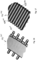
- FIGS. 21 - 27 show transmission components of transmissions with a rotorless motor, in which the respective transmission is driven by deformation or displacement of a traction mechanism or displacement of an internal or external toothing by means of electromagnetic forces of a stator.
- the electromagnetic forces move a first toothing or pins along a second toothing, which is thereby caused to rotate, with the electromagnetic forces acting primarily in a radial direction.
- the transmission components Figures 21 to 27 can be used in particular in an eccentric gear, a cycloidal gear or a harmonic chain or pin ring gear to generate a gear reduction or translation.
- the transmission components Figures 21 to 27 can also be used in particular in the transmissions disclosed in PCT/IB2017/057452, with the components located between the stator and the inner and outer wheel in the torque curve being replaced by the Figures 21 to 27 components shown schematically can be replaced or suitably modified.
- the toothing or the pins can be provided with magnetic areas or with permanent magnets or consist of a magnetic material.
- the toothing or the pins can also be guided by a mechanical guide in addition to being guided by the electromagnetic forces, in particular if the entire toothing or the entire pin ring is guided on a predetermined path, for example on an eccentric circular path.
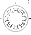
- the figures 21 and 22 show transmissions in which a traction means, in particular a pin ring, is moved by electromagnetic forces of a motor along an inner toothing and an outer toothing.
- the first area is an area of minimum contact or engagement with the external teeth and maximum contact or engagement with the internal teeth.
- the second area is an area of maximum contact or engagement with the external teeth and minimum contact or engagement with the internal teeth.
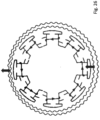
- the figures 23 and 24 show transmissions in which a traction mechanism, in particular a pin ring, is elliptically deformed by electromagnetic forces of a motor and is thereby moved along an inner toothing and an outer toothing.
- In 23 and 24 is indicated by a vertical pair of arrows that a pin ring is pushed apart in a first area and a second area radially opposite thereto, and it is indicated by a horizontal pair of arrows that the pin ring is pushed apart in a third area and a fourth area radially opposite thereto area is contracted.
- the pushing apart, the pulling together or both takes place as a result of electromagnetic forces exerted by the stator, it being possible in particular for the electromagnetic forces to be electrostatic forces.
- the third and fourth areas are offset from the first area and the second area by 90 degrees.
- the first area and the second area are areas of minimum contact or engagement with the internal gear and maximum contact or engagement with the internal gear.
- the third area and the fourth area are areas of maximum contact or meshing with the internal teeth and minimum contact or meshing with the external teeth.
- the stator windings of the stator are driven or energized such that the first area, the second area, the third area and the fourth area rotate about a central central axis.
- the figures 25 and 26 show gears in which an internal toothing is moved along an external toothing by electromagnetic forces of a stator, similar to the case, for example, in a cycloidal gear.
- no traction mechanism is arranged between the internal toothing and the external toothing. Instead, the internal toothing meshes directly with the external toothing or rolls on the external toothing.
- a lower arrow indicates that an internal toothing is moved away from an external toothing in a first area and is pressed into the external toothing in a second area radially opposite thereto.
- the first area is an area of minimal contact or engagement with the external gear.
- the second area is an area of maximum contact or engagement with the external gear.
- the stator windings of the stator are controlled or energized in such a way that the first area and the second area opposite thereto rotate about a central central axis.
- the Figures 21 to 26 show three- or six-pole electric motors or stators. However, electric motors with 4 pole shoes or with more than 6 pole shoes can also be used. For reasons of clarity, the windings on the three-pole motors are in Figures 21 to 26 not shown and the connections of the windings in the six-pole motors are in Figures 21 to 26 Not shown.
- Each pole shoe of an electric motor according to the present description can have its own winding, which is controlled separately, or pole shoes can be connected in series and controlled together.
- the pole pieces connected in series can have the same number of turns or different numbers of turns and they can be wound in the same sense or in opposite senses.
- opposing pole shoes can be connected in series and wound in opposite directions to generate forces of the same magnitude that are opposite to one another, which is advantageous, for example, for an elliptical deformation of a pin ring.
- pole shoe is provided with a winding, but that, for example, only every second pole shoe is wound around. If the pole shoes can be controlled individually, for example by power electronics, or if each pair of opposite pole shoes can be controlled individually, there is improved fine control of the control.
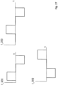
- FIG. 27 shows an example of a simple control of a three-pole motor, in which the pole shoes of the three-pole motor are supplied with current separately, with a predefined signal is used.
- the current I3(t) of the third pole shoe is opposite to the current I1(t) of the first pole shoe and the current I2(t) of the second pole shoe is opposite to the current of the first pole shoe by the duration of the constant signal of I1(t). out of phase.
- the opposite current flow can be achieved, for example, by opposite winding or by separate current flows.
- an amplitude can vary instead of being constant in sections, as in 27 shown.
- a control circuit such as a PID controller can be used instead of the in 27 shown feed-forward control can be used.
- the current signals in the stator coils can be used as sensor signals for the control loop, which makes it possible to avoid installing separate sensors, such as Hall sensors, for example.
- the current signals can be measured during a control pause in which the respective stator winding is not energized.
- the parameters of the control circuit can be changed according to the requirements, for example to produce a predetermined torque or to produce a predetermined speed of rotation.
- 29 shows a cross section through a toothed belt 102'', 102′′′, 102 (IV) with a shifted gap arrangement.
- FIG. 30 shows a cross-section through a toothed belt 102 (VII) with a shifted gap arrangement, in which a rear side of the internal toothing forms the external toothing.
- a thickness of the toothed belt is not drawn to scale in relation to a height of the teeth.
Landscapes
- Engineering & Computer Science (AREA)
- General Engineering & Computer Science (AREA)
- Mechanical Engineering (AREA)
- Retarders (AREA)
- Gears, Cams (AREA)
- Devices For Conveying Motion By Means Of Endless Flexible Members (AREA)
- Pulleys (AREA)
Applications Claiming Priority (3)
| Application Number | Priority Date | Filing Date | Title |
|---|---|---|---|
| IB2018053897 | 2018-05-31 | ||
| PCT/IB2019/054085 WO2019229574A1 (fr) | 2018-05-31 | 2019-05-17 | Moyen de traction avec denture interne et denture externe et engrenage avec moyen de traction |
| EP19735628.0A EP3803153B1 (fr) | 2018-05-31 | 2019-05-17 | Engrenage avec moyen de traction |
Related Parent Applications (2)
| Application Number | Title | Priority Date | Filing Date |
|---|---|---|---|
| EP19735628.0A Division EP3803153B1 (fr) | 2018-05-31 | 2019-05-17 | Engrenage avec moyen de traction |
| EP19735628.0A Division-Into EP3803153B1 (fr) | 2018-05-31 | 2019-05-17 | Engrenage avec moyen de traction |
Publications (2)
| Publication Number | Publication Date |
|---|---|
| EP4234973A2 true EP4234973A2 (fr) | 2023-08-30 |
| EP4234973A3 EP4234973A3 (fr) | 2023-10-25 |
Family
ID=67145836
Family Applications (2)
| Application Number | Title | Priority Date | Filing Date |
|---|---|---|---|
| EP23179082.5A Pending EP4234973A3 (fr) | 2018-05-31 | 2019-05-17 | Engrenage avec moyen de traction |
| EP19735628.0A Active EP3803153B1 (fr) | 2018-05-31 | 2019-05-17 | Engrenage avec moyen de traction |
Family Applications After (1)
| Application Number | Title | Priority Date | Filing Date |
|---|---|---|---|
| EP19735628.0A Active EP3803153B1 (fr) | 2018-05-31 | 2019-05-17 | Engrenage avec moyen de traction |
Country Status (5)
| Country | Link |
|---|---|
| US (2) | US12117065B2 (fr) |
| EP (2) | EP4234973A3 (fr) |
| JP (2) | JP7502999B2 (fr) |
| CN (2) | CN115750725A (fr) |
| WO (1) | WO2019229574A1 (fr) |
Families Citing this family (6)
| Publication number | Priority date | Publication date | Assignee | Title |
|---|---|---|---|---|
| EP2672147B1 (fr) | 2009-03-30 | 2020-01-01 | TQ-Systems GmbH | Véhicule avec unité moteur-engrenage |
| US11280394B2 (en) | 2009-03-30 | 2022-03-22 | Tq-Systems Gmbh | Gear, motor-gear unit, vehicle, generator with a gear, and force transmitting element |
| EP4400400A3 (fr) | 2013-03-20 | 2025-01-22 | TQ-Systems GmbH | Engrenage harmonique à pinring |
| DE102016122845A1 (de) | 2016-11-28 | 2018-05-30 | Tq-Systems Gmbh | Harmonisches Pinring-Getriebe, Drehmomentmessvorrichtung und Freilaufanordnung |
| EP4234973A3 (fr) | 2018-05-31 | 2023-10-25 | TQ-Systems GmbH | Engrenage avec moyen de traction |
| US20240271688A1 (en) * | 2021-09-18 | 2024-08-15 | Tq-Systems Gmbh | Harmonic drive comprising a transmitter ring without pins |
Family Cites Families (157)
| Publication number | Priority date | Publication date | Assignee | Title |
|---|---|---|---|---|
| US618190A (en) | 1899-01-24 | George frederick sturgess | ||
| US499694A (en) | 1893-06-13 | To charles n | ||
| US550474A (en) | 1895-11-26 | Changeable driving-gear | ||
| US573230A (en) | 1896-12-15 | Gearing for bicycles | ||
| US541713A (en) | 1895-06-25 | Changeable driving-gear | ||
| US1423028A (en) | 1918-07-13 | 1922-07-18 | Roth Ernest | Driving means for tanning drums |
| US1670144A (en) | 1926-03-08 | 1928-05-15 | Thomas S Ewart | Reverse drive |
| US1877338A (en) | 1929-10-23 | 1932-09-13 | Diamond Chain And Mfg Company | Chain drive |
| US2210240A (en) | 1938-08-03 | 1940-08-06 | Homer K Herrick | Variable transmission mechanism |
| US2326235A (en) | 1940-03-26 | 1943-08-10 | Magus A G | Tread crank mechanism, particularly for cycles |
| US2852954A (en) | 1954-03-05 | 1958-09-23 | Hobbs Transmission Ltd | Power transmission gears |
| US2941421A (en) | 1957-10-08 | 1960-06-21 | Plotti Riccardo | Variable speed transmission suitable for reversing the rotation sense |
| US2966808A (en) | 1958-12-23 | 1961-01-03 | Curtiss Wright Corp | Power actuated hinge device |
| US3068719A (en) | 1961-08-11 | 1962-12-18 | Bell Aerospace Corp | Mechanical drive |
| US3148560A (en) | 1962-11-05 | 1964-09-15 | Emerson Electric Co | Variable speed drive mechanism utilizing belts and pulleys |
| US3258994A (en) | 1963-06-03 | 1966-07-05 | Alex M Gorfin | Speed changing device |
| US3468175A (en) | 1967-08-15 | 1969-09-23 | Jan W Rabek | Transmission |
| US3726158A (en) | 1971-02-04 | 1973-04-10 | H Brown | Speed-reducing coupling |
| JPS5114653B2 (fr) | 1971-08-30 | 1976-05-11 | ||
| US3861242A (en) | 1973-11-07 | 1975-01-21 | Esco Mfg Co | Composite gear structure |
| US3893532A (en) | 1974-04-29 | 1975-07-08 | Panpacific Recreational Produc | Power assisted golf cart |
| DE2433675C3 (de) | 1974-07-12 | 1981-07-23 | Braren, Rudolf, 8000 München | Planetengetriebe mit Exzenter und Zyklidenverzahnung |
| GB1519588A (en) | 1974-08-02 | 1978-08-02 | Precision Mechanical Dev | Motion transmiting devices |
| US3950950A (en) | 1975-05-05 | 1976-04-20 | E. I. Du Pont De Nemours And Company | Rotary Rankine engine powered electric generating apparatus |
| US4060006A (en) | 1976-09-20 | 1977-11-29 | International Business Machines Corporation | Device for and method of affixing the ends of a substantially plastic ladder chain to make a continuous ladder chain thereof |
| US4117746A (en) | 1976-10-29 | 1978-10-03 | Compudrive Corporation | Orbital drive mechanism |
| US4072062A (en) * | 1976-12-27 | 1978-02-07 | International Harvester Company | Self-cleaning sprocket |
| US4227092A (en) | 1977-11-30 | 1980-10-07 | The United States Of America As Represented By The Secretary Of The Army | Hand cranked electrical power source |
| US4235129A (en) | 1978-03-30 | 1980-11-25 | Isamu Takasu | Speed reduction mechanism |
| US4194415A (en) | 1978-05-08 | 1980-03-25 | Dimitracopoulos Panayotis C | Quadrant drive |
| US4223757A (en) | 1978-06-30 | 1980-09-23 | Gustafson Mfg. Co. | Forward and reverse power control apparatus |
| AT372767B (de) | 1978-08-24 | 1983-11-10 | Falkner Raimund | Untersetzungsgetriebe |
| DK541978A (da) | 1978-11-30 | 1980-05-31 | Roe Ka Teknik Aps | Gear |
| US4307630A (en) | 1979-10-15 | 1981-12-29 | Osborn Merritt A | Gearing |
| DE3009454A1 (de) | 1980-03-12 | 1981-09-24 | Fried. Krupp Gmbh, 4300 Essen | Messeinheit zur ermittlung der belastung von wellen |
| IE51023B1 (en) | 1980-04-02 | 1986-09-03 | Precision Mechanical Dev | Motion transmitting devices having a toothed wheel and independently movable meshing elements |
| US4429595A (en) | 1980-10-23 | 1984-02-07 | Emerson Electric Co. | Motion transmitting device |
| US4449425A (en) | 1981-02-09 | 1984-05-22 | Quadrant Drive Bv | Motion transmitting devices |
| DE3131612A1 (de) | 1981-08-10 | 1983-02-24 | Zahnräderfabrik Renk AG, 8900 Augsburg | Getriebe zur positionierung von sonnenenergie-kollektoren |
| US4471672A (en) | 1981-11-18 | 1984-09-18 | Emerson Electric Co. | Motion transmitting system |
| US4567790A (en) | 1981-11-18 | 1986-02-04 | Emerson Electric Company | Motion transmitting system |
| US4518308A (en) | 1982-03-01 | 1985-05-21 | Acrobe Technology Inc. | Manipulator apparatus |
| JPS58163638A (ja) * | 1982-03-25 | 1983-09-28 | Mitsuboshi Belting Ltd | ゴム製歯付ベルトの製造用組立モ−ルド |
| US4584904A (en) | 1982-03-26 | 1986-04-29 | Advanced Energy Concepts '81, Limited | Epicyclic transmission having free rolling roller driving elements |
| JPS58220720A (ja) | 1982-06-16 | 1983-12-22 | Mitsuboshi Belting Ltd | タイミングベルトならびにダブルタイミングベルトの製造方法 |
| EP0113375B1 (fr) | 1982-06-18 | 1987-09-09 | Matsushita Electric Industrial Co., Ltd. | Engrenage reducteur |
| JPS59187152A (ja) | 1983-04-06 | 1984-10-24 | Yamaha Motor Co Ltd | 減速装置 |
| US4491033A (en) | 1983-06-23 | 1985-01-01 | Usm Corporation | Double eccentric wave generator arrangement |
| US4604916A (en) | 1984-02-10 | 1986-08-12 | Advanced Energy Concepts '81 Ltd. | Epicyclic transmission having cam driven roller retainer |
| JPH0243813B2 (ja) | 1984-06-13 | 1990-10-01 | Mitsubishi Metal Corp | Gasutaabinyokokyodocokitainetsugokin |
| US4583962A (en) | 1984-12-07 | 1986-04-22 | Litens Automotive Inc. | Timing belt tensioner with damped constant spring tensioning and belt tooth disegagement prevention |
| DE3667832D1 (de) | 1985-04-12 | 1990-02-01 | Beijing Inst Of Aeronautics An | Exzentergetriebe mit oszillierenden zaehnen. |
| DE8513367U1 (de) | 1985-05-07 | 1986-06-26 | Krueger-Beuster, Helmut, 2420 Eutin | Umlaufrädergetriebe |
| US4715247A (en) | 1985-09-26 | 1987-12-29 | Kabushiki Kaisha Toshiba | Transmission apparatus with reduced frictional force |
| US4807494A (en) | 1986-07-31 | 1989-02-28 | Lew Hyok S | Stepwise variable speed planetary drive |
| US4729756A (en) | 1987-01-29 | 1988-03-08 | Emerson Electric Co. | Roller chain |
| JP2503027B2 (ja) | 1987-09-21 | 1996-06-05 | 株式会社ハーモニック・ドライブ・システムズ | 撓みかみ合い式歯車装置 |
| DE3738521C1 (de) * | 1987-11-13 | 1988-12-01 | Delta Getriebe Gmbh | Planetengetriebe |
| US4900165A (en) | 1988-08-15 | 1990-02-13 | Union Carbide Corporation | Bearing support system |
| JPH02271144A (ja) | 1989-03-04 | 1990-11-06 | Man Roland Druckmas Ag | 遊星歯車装置 |
| JP2532954B2 (ja) * | 1989-12-13 | 1996-09-11 | ユニッタ株式会社 | 両歯歯付無端ベルトおよびその製造方法 |
| US5445572A (en) | 1991-01-15 | 1995-08-29 | Parker; Bruce H. | Low cost, lightweight differential |
| US5286237A (en) | 1991-08-13 | 1994-02-15 | Sumitomo Heavy Industries, Ltd. | Inscribed meshing planetary gear construction |
| US5123300A (en) | 1991-08-28 | 1992-06-23 | Dynamics Research & Development Corp. | Phasing transmission |
| DE4239963A1 (de) * | 1992-11-27 | 1994-06-01 | Erich Doering | Biegsames Treiborgan für einen Riementrieb |
| DE4309871A1 (de) | 1993-03-26 | 1994-09-29 | Fichtel & Sachs Ag | Anordnung zur Befestigung einer Kupplung an einer Kurbelwelle |
| US5417186A (en) | 1993-06-28 | 1995-05-23 | Clemson University | Dual-acting apparatus for variable valve timing and the like |
| US5456139A (en) | 1993-08-30 | 1995-10-10 | Teppin Seiki Boston, Inc. | Tooth profile arrangement to eliminate tooth intererence in extended contact harmonic drive devices |
| US5662008A (en) | 1993-08-30 | 1997-09-02 | Teijin Seiki Boston, Inc. | Extended contact harmonic drive devices |
| DE19549626A1 (de) | 1995-02-01 | 1999-09-09 | Mannesmann Sachs Ag | Betätigungsvorrichtung, insbesondere für ein Fahrzeug |
| US5772573A (en) | 1996-02-26 | 1998-06-30 | Baker Hughes Incorporated | Decanter centrifuge and gear box with harmonic drive and associated operating method |
| JP3698855B2 (ja) | 1996-07-31 | 2005-09-21 | ナブテスコ株式会社 | 回転運動伝動装置 |
| JP3786377B2 (ja) | 1996-10-02 | 2006-06-14 | 株式会社ハーモニック・ドライブ・システムズ | 位相調整装置 |
| JP3336603B2 (ja) | 1996-11-05 | 2002-10-21 | トヨタ自動車株式会社 | 動力舵取り装置 |
| US5954611A (en) | 1997-06-04 | 1999-09-21 | Davinci Technology Corporation | Planetary belt transmission and drive |
| KR100262485B1 (ko) | 1997-05-15 | 2000-08-01 | 정재연 | 일방향 자전거 구동장치 |
| KR100455071B1 (ko) | 1997-07-15 | 2004-11-08 | 에임브릿지 피티와이 엘티디 | 오비탈 기어 동력전달용의 기어 프로파일과 오비탈 기어동력전달과 오비탈기어 동력전달을 이용한 권양기 |
| JP3924858B2 (ja) | 1997-09-02 | 2007-06-06 | 株式会社明電舎 | ホームエレベータ昇降用駆動装置 |
| ATE210243T1 (de) | 1997-09-19 | 2001-12-15 | Tcg Unitech Ag | Vorrichtung zur verstellung der nockenwelle einer brennkraftmaschine mit innerer verbrennung |
| CN2312173Y (zh) | 1997-11-25 | 1999-03-31 | 北京中技克美谐波传动有限责任公司 | 一种电动助力自行车 |
| US6191561B1 (en) | 1998-01-16 | 2001-02-20 | Dresser Industries, Inc. | Variable output rotary power generator |
| JPH11227666A (ja) | 1998-02-13 | 1999-08-24 | Bridgestone Cycle Co | 自転車用補助動力装置 |
| JPH11258078A (ja) | 1998-03-09 | 1999-09-24 | Toyoda Mach Works Ltd | トルク検出装置 |
| DE69830314T2 (de) | 1998-03-25 | 2006-02-02 | Harmonic Drive Systems Inc. | Phasenregler |
| US6026711A (en) | 1998-09-10 | 2000-02-22 | Harmonic Drive Technologies | Harmonic drive bearing arrangement |
| US6296072B1 (en) | 1999-01-20 | 2001-10-02 | Opti-Bike Llc | Electric bicycle and methods |
| US6148684A (en) | 1999-03-10 | 2000-11-21 | Heidelberger Druckmaschinen Aktiengesellschaft | Anti-backlash gear |
| US6328006B1 (en) | 1999-03-23 | 2001-12-11 | Tcg Unitech Aktiengesellschaft | Device for adjusting the phase angle of a camshaft of an internal combustion engine |
| DE19917020C2 (de) | 1999-04-15 | 2001-09-13 | Dieter Michael Krone | Meßbuchse zur Erfassung von radialen Lagerkräften |
| US6258007B1 (en) | 1999-05-27 | 2001-07-10 | Teijin Seiki Boston, Inc | Multi-sensor harmonic drive actuator arrangement assembly |
| GB9921159D0 (en) | 1999-09-09 | 1999-11-10 | Walls Robert W | Fluid level alarm |
| DE10012601A1 (de) | 2000-03-04 | 2001-10-04 | Oechsler Ag | Wellgetriebe und Innenrad für ein solches Getriebe |
| DE10010680C2 (de) | 2000-03-04 | 2002-01-03 | Oechsler Ag | Wellgetriebe und Innenrad für ein solches Getriebe |
| DE10026038C2 (de) | 2000-05-25 | 2002-04-25 | Oechsler Ag | Wellgetriebe mit Axialabtrieb |
| JP2003019996A (ja) | 2001-07-09 | 2003-01-21 | Toshio Nakahira | 電気式補助動力付自転車の踏力検出装置 |
| US7294078B2 (en) | 2002-05-21 | 2007-11-13 | Delphi Technologies, Inc. | Over-molded beaded cable for driving applications |
| US7282052B2 (en) | 2002-09-17 | 2007-10-16 | Ebi, L.P. | Unilateral fixator |
| US7249534B1 (en) | 2002-10-15 | 2007-07-31 | Raytheon Company | Leadscrew mechanical drive with differential leadscrew follower structure |
| US6982498B2 (en) | 2003-03-28 | 2006-01-03 | Tharp John E | Hydro-electric farms |
| WO2004088166A1 (fr) | 2003-04-04 | 2004-10-14 | Hammerbeck John P R | Procede et appareil de changement de rapports |
| JP4248334B2 (ja) * | 2003-07-18 | 2009-04-02 | 株式会社ハーモニック・ドライブ・システムズ | 波動歯車装置 |
| US20070158497A1 (en) | 2003-10-09 | 2007-07-12 | Edelson Jonathan S | Geared wheel motor design |
| DE102004018947A1 (de) | 2004-04-20 | 2005-11-17 | Daimlerchrysler Ag | Verstellgetriebe für eine Nockenwellenanordnung |
| JP2005330990A (ja) | 2004-05-18 | 2005-12-02 | Mamoru Tamura | 減速機構 |
| EP1764530B1 (fr) | 2004-07-02 | 2012-03-28 | Honda Motor Co., Ltd. | Mecanisme d'entrainement avec reducteur de vitesse |
| DE102004032141A1 (de) | 2004-07-02 | 2006-02-23 | Ina-Schaeffler Kg | Nockenwellenversteller |
| US20060027201A1 (en) | 2004-08-09 | 2006-02-09 | Ryou Ono | Engine starter |
| US7178427B2 (en) | 2004-08-26 | 2007-02-20 | Honeywell International, Inc. | Motor driven harmonic drive actuator having an interposed output mechanism |
| EP1824699B1 (fr) | 2004-11-22 | 2010-10-06 | Bosch Rexroth Corporation | Systeme d'entrainement hybride hydro-electrique pour automobile |
| US20060135305A1 (en) | 2004-12-13 | 2006-06-22 | Shmuel Erez | Harmonic belt drive |
| US7527130B2 (en) * | 2005-04-29 | 2009-05-05 | Delphi Technologies, Inc. | Harmonic drive linear actuator |
| US20060283289A1 (en) * | 2005-06-16 | 2006-12-21 | Baudendistel Thomas A | Harmonic drive motor with flex-spline interlock |
| DE102005032222A1 (de) | 2005-07-09 | 2007-01-25 | Schaeffler Kg | Lageranordnung zur Lagerung wenigstens eines Maschinenelements an einer Stütze |
| EP1922495A1 (fr) | 2005-09-06 | 2008-05-21 | The Timken Company | Palier capteur de charge |
| US7240570B2 (en) | 2005-09-06 | 2007-07-10 | The Timken Company | Load-sensing bearing |
| US7552664B2 (en) | 2005-11-04 | 2009-06-30 | Northrop Grumman Guidance and Electronics Co., Inc. | Harmonic drive gear assembly with asymmetrical wave generator and associated flexspline |
| JP2007155076A (ja) | 2005-12-08 | 2007-06-21 | Nabtesco Corp | 車輪駆動装置 |
| JP2007205397A (ja) | 2006-01-31 | 2007-08-16 | Jtekt Corp | 波動歯車装置及び伝達比可変装置 |
| SG139701A1 (en) * | 2006-08-11 | 2008-02-29 | Inventio Ag | Lift installation with a belt, belt for such a lift installation, method of producing such a belt, composite of such belts and method for assembly of such a composite in a lift installation |
| US7421990B2 (en) | 2006-08-22 | 2008-09-09 | Delphi Technologies, Inc. | Harmonic drive camshaft phaser |
| DE102006042786B4 (de) | 2006-09-08 | 2008-09-11 | Wittenstein Ag | Hohlwellengetriebe |
| JP4222407B2 (ja) | 2006-10-25 | 2009-02-12 | トヨタ自動車株式会社 | 動力出力装置およびハイブリッド自動車 |
| US8065926B2 (en) | 2006-11-06 | 2011-11-29 | Sram, Llc | Crankset based bicycle power measurement |
| JP4397927B2 (ja) | 2006-12-28 | 2010-01-13 | 本田技研工業株式会社 | 自動二輪車用エンジン |
| JP2008174069A (ja) | 2007-01-18 | 2008-07-31 | Mazda Motor Corp | ホイール駆動装置 |
| JP4999475B2 (ja) | 2007-01-24 | 2012-08-15 | 株式会社ハーモニック・ドライブ・システムズ | フラット型波動歯車装置 |
| CN101657653B (zh) | 2007-02-12 | 2014-07-16 | 福博科知识产权有限责任公司 | 一种传动装置 |
| DE102007019607A1 (de) | 2007-04-02 | 2008-10-16 | Wittenstein Ag | Koaxialgetriebe, insbesondere Hohlwellengetriebe für die industrielle Antriebstechnik |
| US7699329B2 (en) | 2007-04-11 | 2010-04-20 | Sram, Llc | Mounting system for an internal bicycle transmission |
| US20090139357A1 (en) | 2007-12-04 | 2009-06-04 | Harmonic Drive Systems Inc. | Method For Setting Nonpositive Deflection, Maximum Meshable Tooth Profile In Flat Wave Gear Device |
| DE102007055883A1 (de) | 2007-12-20 | 2009-06-25 | Forschungsgesellschaft für Zahnräder und Getriebe mbH | Getriebevorrichtung mit wenigstens zwei Ausgangswellen |
| US7777385B2 (en) | 2008-05-15 | 2010-08-17 | Honeywell International Inc. | Compact, electromagnetically braked actuator assembly |
| JP5064300B2 (ja) | 2008-05-28 | 2012-10-31 | 株式会社ハーモニック・ドライブ・システムズ | 波動歯車式直動機構 |
| KR100988215B1 (ko) | 2008-06-24 | 2010-10-18 | 한국과학기술연구원 | 전위기어를 이용하는 하모닉 감속기 |
| JP4948479B2 (ja) | 2008-06-26 | 2012-06-06 | 株式会社ハーモニック・ドライブ・システムズ | 複合型波動歯車減速機 |
| WO2010012283A1 (fr) | 2008-07-26 | 2010-02-04 | Ab Skf | Ensemble roulement de roue |
| KR100987950B1 (ko) * | 2008-12-18 | 2010-10-18 | 삼익에이치디에스(주) | 탄성 이중 링기어형 감속기 |
| DE102009010001A1 (de) * | 2009-02-23 | 2010-09-02 | Ims Gear Gmbh | Planetenrad mit einem eine axiale Nut aufweisenden Lagerbolzen |
| EP2672147B1 (fr) | 2009-03-30 | 2020-01-01 | TQ-Systems GmbH | Véhicule avec unité moteur-engrenage |
| US11280394B2 (en) | 2009-03-30 | 2022-03-22 | Tq-Systems Gmbh | Gear, motor-gear unit, vehicle, generator with a gear, and force transmitting element |
| US8852048B2 (en) | 2010-08-19 | 2014-10-07 | Ben Shelef | Planetary harmonic differential transmission |
| EP3865734A1 (fr) | 2010-10-07 | 2021-08-18 | TQ-Systems GmbH | Engrenage, unité moteur-engrenage, véhicule, générateur avec engrenage et élément de transmission de force |
| FI124566B (fi) | 2010-12-13 | 2014-10-15 | Konecranes Oyj | Sovitelma laakerin säteisvoimien mittaamiseksi |
| JP2014019169A (ja) | 2012-07-12 | 2014-02-03 | Nissan Motor Co Ltd | 駆動力配分装置 |
| DE202013012409U1 (de) | 2012-10-18 | 2016-10-13 | Tq-Systems Gmbh | Harmonisches Pin-Ring-Getriebe und Pinring |
| DE202013012416U1 (de) | 2012-10-18 | 2016-10-20 | Tq-Systems Gmbh | Zahngeometrien für einen Harmonic-Pin-Ring-Antrieb |
| GB2511101B (en) | 2013-02-22 | 2017-05-10 | Transense Tech Plc | Torque measurement flexplates |
| US9228651B2 (en) | 2013-03-05 | 2016-01-05 | Karem Aircraft, Inc. | Compact torque-transmitting gearbox with high reduction ratio |
| EP4400400A3 (fr) * | 2013-03-20 | 2025-01-22 | TQ-Systems GmbH | Engrenage harmonique à pinring |
| JP6217577B2 (ja) * | 2014-09-24 | 2017-10-25 | 株式会社デンソー | 内接噛合遊星歯車機構 |
| DE102014115043B4 (de) * | 2014-10-16 | 2021-12-23 | Obrist Technologies Gmbh | Stromaggregat |
| CN104276251B (zh) | 2014-10-31 | 2017-05-03 | 太仓市荣驰电机有限公司 | 一种电动车中轴力矩传感系统 |
| CN104374511B (zh) | 2014-12-09 | 2016-06-29 | 株洲联诚集团有限责任公司 | 一种三相感应电机转子轴承径向力测量装置及测量方法 |
| DE102016122845A1 (de) * | 2016-11-28 | 2018-05-30 | Tq-Systems Gmbh | Harmonisches Pinring-Getriebe, Drehmomentmessvorrichtung und Freilaufanordnung |
| EP4234973A3 (fr) | 2018-05-31 | 2023-10-25 | TQ-Systems GmbH | Engrenage avec moyen de traction |
| EP4354109B1 (fr) | 2021-07-26 | 2026-01-14 | TQ-Systems GmbH | Unité de moteur et bicyclette assistée électriquement |
| US20240271688A1 (en) | 2021-09-18 | 2024-08-15 | Tq-Systems Gmbh | Harmonic drive comprising a transmitter ring without pins |
-
2019
- 2019-05-17 EP EP23179082.5A patent/EP4234973A3/fr active Pending
- 2019-05-17 JP JP2020566746A patent/JP7502999B2/ja active Active
- 2019-05-17 US US17/057,307 patent/US12117065B2/en active Active
- 2019-05-17 CN CN202211548023.7A patent/CN115750725A/zh active Pending
- 2019-05-17 WO PCT/IB2019/054085 patent/WO2019229574A1/fr not_active Ceased
- 2019-05-17 CN CN201980036472.3A patent/CN112219044B/zh active Active
- 2019-05-17 EP EP19735628.0A patent/EP3803153B1/fr active Active
-
2024
- 2024-06-07 JP JP2024092884A patent/JP7808642B2/ja active Active
- 2024-09-26 US US18/898,210 patent/US20250043844A1/en active Pending
Also Published As
| Publication number | Publication date |
|---|---|
| US20210332869A1 (en) | 2021-10-28 |
| CN112219044A (zh) | 2021-01-12 |
| EP3803153A1 (fr) | 2021-04-14 |
| JP2024110001A (ja) | 2024-08-14 |
| US20250043844A1 (en) | 2025-02-06 |
| EP3803153B1 (fr) | 2023-07-19 |
| WO2019229574A1 (fr) | 2019-12-05 |
| CN112219044B (zh) | 2022-12-27 |
| EP4234973A3 (fr) | 2023-10-25 |
| JP7502999B2 (ja) | 2024-06-19 |
| JP2021525852A (ja) | 2021-09-27 |
| JP7808642B2 (ja) | 2026-01-29 |
| US12117065B2 (en) | 2024-10-15 |
| CN115750725A (zh) | 2023-03-07 |
Similar Documents
| Publication | Publication Date | Title |
|---|---|---|
| EP4234973A2 (fr) | Engrenage avec moyen de traction | |
| EP2976551B1 (fr) | Démultiplicateur harmonique à couronne de broches | |
| EP3545276B1 (fr) | Cellule de mesure de force pour mesurer une force radiale | |
| DE102007056391B4 (de) | Getriebestufe | |
| EP1136657B1 (fr) | Dispositif déphaseur d'arbre à cames | |
| DE112013005415T5 (de) | Planeten-Nockenwellenverstellsystem mit geteiltem Hohlrad | |
| DE202010018413U1 (de) | Getriebe, Motor-Getriebe-Einheit, Fahrzeug sowie Generator mit einem Getriebe | |
| EP1718846A1 (fr) | Dispositif de reglage electrique d'arbre a cames | |
| EP3483473A1 (fr) | Transmission | |
| DE102021119145A1 (de) | Antriebsanordnung für ein muskelbetriebenes Fahrzeug mit zwei baugleichen Getriebeeinrichtungen sowie Fahrzeug mit der Antriebsanordnung | |
| DE102012205849B4 (de) | Elektromotoranordnung mit beweglichen Rotorsegmenten, um eine gegenelektromotorische Kraft zu verringern | |
| WO2005100081A2 (fr) | Unite d'entrainement d'un element de reglage d'un siege de vehicule | |
| WO2005046030A1 (fr) | Unite d'entrainement/transmission | |
| EP4291480A1 (fr) | Ensemble d'entraînement comprenant une boîte de vitesses à excentrique pour un véhicule à propulsion humaine, et véhicule comprenant ledit ensemble d'entraînement | |
| DE102005053119A1 (de) | Vorrichtung zur Verstellung der relativen Drehwinkellage zwischen Nockenwelle und Antriebsrad | |
| DE102015223914A1 (de) | Umlaufrädergetriebe für eine Kraftfahrzeugantriebseinheit | |
| DE102013211801B4 (de) | Elektromechanischer Aktor | |
| EP2704920A2 (fr) | Ensemble engrenage planétaire pour un mécanisme de réglage de siège et procédé de fonctionnement d'un ensemble engrenage planétaire de ce type | |
| DE10151878A1 (de) | Mehrstufiges Getriebe mit Wellgetriebe | |
| DE102023132627B4 (de) | Vorrichtung für ein muskelbetriebenes Fahrzeug | |
| DE102015120244A1 (de) | Getriebestufe für eine Getriebeanordnung, Getriebeanordnung und Antriebsvorrichtung mit einem Elektromotor und einer Getriebeanordnung | |
| DE10056597A1 (de) | Schaltgetriebe für ein Fahrrad mit Elektromotor | |
| DE102022116701A1 (de) | Antriebsanordnung mit Exzentergetriebe für ein muskelbetriebenes Fahrzeug sowie Fahrzeug mit der Antriebsanordnung | |
| DE102023100033A1 (de) | Planetengetriebe | |
| DE102021117436A1 (de) | Exzentergetriebe, Generatormodul mit dem Exzentergetriebe sowie Fahrzeug mit dem Exzentergetriebe |
Legal Events
| Date | Code | Title | Description |
|---|---|---|---|
| PUAI | Public reference made under article 153(3) epc to a published international application that has entered the european phase |
Free format text: ORIGINAL CODE: 0009012 |
|
| STAA | Information on the status of an ep patent application or granted ep patent |
Free format text: STATUS: THE APPLICATION HAS BEEN PUBLISHED |
|
| AC | Divisional application: reference to earlier application |
Ref document number: 3803153 Country of ref document: EP Kind code of ref document: P |
|
| AK | Designated contracting states |
Kind code of ref document: A2 Designated state(s): AL AT BE BG CH CY CZ DE DK EE ES FI FR GB GR HR HU IE IS IT LI LT LU LV MC MK MT NL NO PL PT RO RS SE SI SK SM TR |
|
| PUAL | Search report despatched |
Free format text: ORIGINAL CODE: 0009013 |
|
| AK | Designated contracting states |
Kind code of ref document: A3 Designated state(s): AL AT BE BG CH CY CZ DE DK EE ES FI FR GB GR HR HU IE IS IT LI LT LU LV MC MK MT NL NO PL PT RO RS SE SI SK SM TR |
|
| RIC1 | Information provided on ipc code assigned before grant |
Ipc: F16H 49/00 20060101ALI20230919BHEP Ipc: F16G 1/28 20060101AFI20230919BHEP |
|
| STAA | Information on the status of an ep patent application or granted ep patent |
Free format text: STATUS: REQUEST FOR EXAMINATION WAS MADE |
|
| 17P | Request for examination filed |
Effective date: 20240404 |
|
| RBV | Designated contracting states (corrected) |
Designated state(s): AL AT BE BG CH CY CZ DE DK EE ES FI FR GB GR HR HU IE IS IT LI LT LU LV MC MK MT NL NO PL PT RO RS SE SI SK SM TR |
|
| STAA | Information on the status of an ep patent application or granted ep patent |
Free format text: STATUS: EXAMINATION IS IN PROGRESS |
|
| 17Q | First examination report despatched |
Effective date: 20250402 |