EP4239237A1 - Joint de tuyau et procédé pour assembler un anneau de pression et un tuyau - Google Patents
Joint de tuyau et procédé pour assembler un anneau de pression et un tuyau Download PDFInfo
- Publication number
- EP4239237A1 EP4239237A1 EP21889138.0A EP21889138A EP4239237A1 EP 4239237 A1 EP4239237 A1 EP 4239237A1 EP 21889138 A EP21889138 A EP 21889138A EP 4239237 A1 EP4239237 A1 EP 4239237A1
- Authority
- EP
- European Patent Office
- Prior art keywords
- socket
- seal member
- pipe
- gland
- tapered surface
- Prior art date
- Legal status (The legal status is an assumption and is not a legal conclusion. Google has not performed a legal analysis and makes no representation as to the accuracy of the status listed.)
- Pending
Links
Images






Classifications
-
- F—MECHANICAL ENGINEERING; LIGHTING; HEATING; WEAPONS; BLASTING
- F16—ENGINEERING ELEMENTS AND UNITS; GENERAL MEASURES FOR PRODUCING AND MAINTAINING EFFECTIVE FUNCTIONING OF MACHINES OR INSTALLATIONS; THERMAL INSULATION IN GENERAL
- F16L—PIPES; JOINTS OR FITTINGS FOR PIPES; SUPPORTS FOR PIPES, CABLES OR PROTECTIVE TUBING; MEANS FOR THERMAL INSULATION IN GENERAL
- F16L21/00—Joints with sleeve or socket
- F16L21/02—Joints with sleeve or socket with elastic sealing rings between pipe and sleeve or between pipe and socket, e.g. with rolling or other prefabricated profiled rings
- F16L21/04—Joints with sleeve or socket with elastic sealing rings between pipe and sleeve or between pipe and socket, e.g. with rolling or other prefabricated profiled rings in which sealing rings are compressed by axially-movable members
-
- F—MECHANICAL ENGINEERING; LIGHTING; HEATING; WEAPONS; BLASTING
- F16—ENGINEERING ELEMENTS AND UNITS; GENERAL MEASURES FOR PRODUCING AND MAINTAINING EFFECTIVE FUNCTIONING OF MACHINES OR INSTALLATIONS; THERMAL INSULATION IN GENERAL
- F16L—PIPES; JOINTS OR FITTINGS FOR PIPES; SUPPORTS FOR PIPES, CABLES OR PROTECTIVE TUBING; MEANS FOR THERMAL INSULATION IN GENERAL
- F16L37/00—Couplings of the quick-acting type
- F16L37/08—Couplings of the quick-acting type in which the connection between abutting or axially overlapping ends is maintained by locking members
- F16L37/084—Couplings of the quick-acting type in which the connection between abutting or axially overlapping ends is maintained by locking members combined with automatic locking
- F16L37/088—Couplings of the quick-acting type in which the connection between abutting or axially overlapping ends is maintained by locking members combined with automatic locking by means of a split elastic ring
-
- F—MECHANICAL ENGINEERING; LIGHTING; HEATING; WEAPONS; BLASTING
- F16—ENGINEERING ELEMENTS AND UNITS; GENERAL MEASURES FOR PRODUCING AND MAINTAINING EFFECTIVE FUNCTIONING OF MACHINES OR INSTALLATIONS; THERMAL INSULATION IN GENERAL
- F16L—PIPES; JOINTS OR FITTINGS FOR PIPES; SUPPORTS FOR PIPES, CABLES OR PROTECTIVE TUBING; MEANS FOR THERMAL INSULATION IN GENERAL
- F16L21/00—Joints with sleeve or socket
- F16L21/08—Joints with sleeve or socket with additional locking means
Definitions
- the present invention relates to a pipe joint in which a spigot formed in one pipe is inserted into a socket formed in another pipe, a gland used in the pipe joint, and a method for joining pipes.
- a pipe joint 110 illustrated in FIG. 16 is already known.
- the pipe joint 110 is configured as follows.
- a spigot 102 formed in one pipe 101 is inserted into a socket 104 formed in another pipe 103.
- a first tapered surface 105 that decreases in diameter progressively toward the back side of the socket 104 is formed on the inner circumference of the socket 104.
- a seal member insertion space 106 is formed throughout the entire circumference between the first tapered surface 105 and the outer circumference of the spigot 102.
- An annular seal member 107 that seals between the inner circumference of the socket 104 and the outer circumference of the spigot 102 is inserted into the seal member insertion space 106.
- a gland 109 that presses the seal member 107 from an opening end face 108 of the socket 104 into the seal member insertion space 106 is externally fitted to the spigot 102, and faces the opening end face 108 of the socket 104 from the outside.
- a socket protrusion 111 that protrudes inward in a pipe diameter direction B from the inner circumference of the socket 104 is formed over the entire circumference.
- a lock ring 112 is accommodated at a position that is further toward the back side of the socket 104 than the socket protrusion 111.
- the spigot 102 passes through the lock ring 112, and a spigot protrusion 113 is formed over the entire circumference on the outer circumference of a tip portion of the spigot 102.
- the spigot protrusion 113 is capable of engaging with the lock ring 112 from the back side of the socket 104 in a separation direction 120 of the one pipe 101. By this means, the spigot 102 is prevented from separating from the socket 104 during the occurrence of an earthquake or the like.
- the gland 109 is attached to the socket 104 through a plurality of bolts 114 and nuts 115.
- the bolts 114 are inserted through bolt insertion holes 116 formed in the gland 109.
- These bolts 114, nuts 115, and bolt insertion holes 116 are formed at predetermined intervals, respectively, in a pipe circumference direction G.
- a plurality of protrusions 117 are provided in the gland 109. Each of these protrusions 117 is located further outward in the pipe diameter direction B than the bolt insertion holes 116.
- the seal member 107 has, at one end part in an insertion direction C, a bulb part 118 which is compressed in the pipe diameter direction B and exerts a sealing function.
- the seal member 107 and the gland 109 are externally fitted to the one pipe 101, the spigot 102 is inserted into the socket 104, and centering is performed to align the central axis of the one pipe 101 with the central axis of the other pipe 103.
- the bolts 114 and the nuts 115 are tightened, and the seal member 107 is pressed from the opening end face 108 of the socket 104 into the seal member insertion space 106 by the gland 109.
- Japanese Patent Laid-Open No. 2010-286110 can be referred to for a description regarding the pipe joint 110 described above.
- seal member 107 If the seal member 107 is slackened in this way, a problem such that the bulb part 118 of the seal member 107 cannot be inserted into the seal member insertion space 106 may occur. Therefore, in the conventional form, it is necessary to perform tightening in a manner so that the tightening torque is equal at all of the bolts 114 and the nuts 115, and consequently it takes time to perform the work to tighten the bolts 114 and the nuts 115.
- An object of the present invention is to provide a pipe joint in which a seal member can be reliably pressed into a seal member insertion space by a gland, and in which it is possible to prevent deformation of the gland, and in which control of the tightening torque of fasteners is not necessary, and to also provide a gland and a method for joining pipes.
- a pipe joint of the present invention is a pipe joint, wherein:
- the bulb part of the seal member is guided into the seal member insertion space from the opening end face of the socket by the second tapered surface of the guide part.
- a bulb center part between an inner circumference and an outer circumference in the pipe diameter direction of the bulb part of the seal member is located further inward in the pipe diameter direction than an end part of the second tapered surface on an opening end face side of the socket.
- the bulb center part of the seal member is located further inward in the pipe diameter direction than an end part of the second tapered surface, even if the fasteners are unevenly tightened when attaching the gland to the socket, and the seal member stretches and slackens in the pipe diameter direction, the bulb part of the seal member will be reliably guided from the opening end face of the socket into the seal member insertion space by the second tapered surface of the guide part.
- a relation that the bulb center part is located further inward in the pipe diameter direction than the end part of the second tapered surface on the opening end face side of the socket is also maintained in the minimum clearance portion.
- the bulb center part of the seal member is located further inward in the pipe diameter direction than the end part of the second tapered surface also in the minimum clearance portion.
- a clearance that is surrounded by an inner circumferential surface of the first protrusion, the second tapered surface, and an outer circumferential surface of the seal member is formed.
- a gland used in the pipe joint according to the present invention is a gland wherein:
- the spigot is inserted into the socket, when the spigot is bent at a predetermined angle with respect to the socket, even if the outer circumference of the spigot comes in contact with the inner circumference of the gland, deformation of the gland can be prevented by the first protrusion and the second protrusion each coming in contact with the opening end face of the socket.
- the weight of the gland can be reduced in comparison to a gland in which the outer circumferential concave portions are not formed.
- a configuration is adopted so that a width in the pipe diameter direction from an inner circumference to an outer circumference of the first protrusion is equal to or greater than a width in the pipe diameter direction from the outer circumference of the first protrusion to the outer circumferential concave portion.
- the strength of the gland can be sufficiently maintained even when a plurality of outer circumferential concave portions are formed in the outer circumferential edge of the gland.
- a method for joining pipes of the present invention is a method for joining pipes in a pipe joint, wherein:
- the method for joining pipes of the present invention preferably includes:
- the seal member when the seal member is pressed into the seal member insertion space by the gland, the bulb part of the seal member is guided into the seal member insertion space from the opening end face of the socket by the second tapered surface of the guide part. Therefore, in a case where the fasteners are unevenly tightened when attaching the gland to the socket, even if the seal member stretches and slackens, because the bulb part of the seal member is guided from the opening end face of the socket into the seal member insertion space by the second tapered surface of the guide part, the seal member can be reliably pressed into the seal member insertion space by the gland.
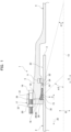
- a pipe joint 1 is constituted by inserting a spigot 3 formed in one pipe 2 into a socket 5 formed in another pipe 4.
- a first tapered surface 8, a straight surface 9, a socket protrusion 10, and a lock ring accommodating groove 11 are formed on the inner circumference of the socket 5.
- the first tapered surface 8 decreases in diameter progressively toward the rear side of the socket 5.
- the straight surface 9 is parallel to a pipe central axis 13 of the pipe 4, and is continuous from a back end part of the first tapered surface 8 to the back side of the socket 5.
- a seal member insertion space 14 is formed throughout the entire circumference between the first tapered surface 8 and the outer circumference of the spigot 3.
- An annular seal member 15 that seals between the inner circumference of the socket 5 and the outer circumference of the spigot 3 is inserted into the seal member insertion space 14.
- a gland 17 that presses the seal member 15 from an opening end face 16 of the socket 5 into the seal member insertion space 14 is externally fitted to the spigot 3, and faces the opening end face 16 of the socket 5 from the outside.
- the gland 17 is attached to the socket 5 through a plurality of T-head bolts 19 (one example of a fastener) and nuts 20 (one example of a fastener).
- a plurality of bolt holes 21 through which the T-head bolts 19 are inserted are formed in the socket 5.
- the lock ring accommodating groove 11 is formed further toward the back side of the socket 5 than the seal member insertion space 14.
- a lock ring 22 is accommodated in the lock ring accommodating groove 11.
- the lock ring 22 is a ring having a split structure in which one portion has been cut.
- the lock ring 22 has elasticity such that the diameter thereof is expanded by expanding the width of the cut portion with a diameter expander (not illustrated in the drawings), and the diameter thereof is reduced to return to the original diameter by removing the diameter expander from the cut portion.
- the spigot 3 passes through the lock ring 22.
- a spigot protrusion 23 is formed over the entire circumference on the outer circumference of a tip portion of the spigot 3.
- the spigot protrusion 23 can engage with the lock ring 22 from the back side of the socket 5 in a separation direction 25 of the one pipe 2, and by this means the spigot 3 is prevented from separating from the socket 5 during the occurrence of an earthquake or the like.
- the socket protrusion 10 protrudes inward in a pipe diameter direction B from the inner circumference of the socket 5, and is formed over the entire circumference between the seal member insertion space 14 and the lock ring accommodating groove 11.
- a centering ring 24 is fitted into a space between the inner circumference of the socket protrusion 10 and the outer circumference of the spigot 3.
- the centering ring 24 is a ring having a split structure in which one portion has been cut, and is made of a material that has elasticity, such as resin.
- the seal member 15 is a ring made of rubber, and has a bulb part 26 having a circular cross section that is provided at one end part in an insertion direction C, and a base part 27 having a trapezoidal cross section that is provided integrally with the bulb part 26. As illustrated in FIG. 1 , in a state in which the seal member 15 is inserted into the seal member insertion space 14, the bulb part 26 is compressed in the pipe diameter direction B and exerts a sealing function.
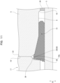
- a guide part 29 that guides the bulb part 26 of the seal member 15 from the opening end face 16 of the socket 5 into the seal member insertion space 14 is formed on the inner circumference of the socket 5.
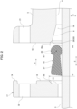
- the guide part 29 has a second tapered surface 30 that decreases in diameter progressively toward the rear side of the socket 5.
- the second tapered surface 30 is formed over the entire circumference between the opening end face 16 and the first tapered surface 8 of the socket 5 in a pipe axis direction E. As illustrated in FIG. 1 , an angle of inclination ⁇ 2 of the second tapered surface 30 with respect to the pipe central axis 13 is greater than an angle of inclination ⁇ 1 of the first tapered surface 8 with respect to the pipe central axis 13.
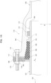
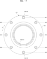
- a plurality of bolt insertion holes 32 (one example of a fastener insertion hole) through which the T-head bolts 19 are inserted, a toric first protrusion 33 which comes in contact with the opening end face 16 of the socket 5, a plurality of second protrusions 34 which come in contact with the opening end face 16, and a concave portion 35 which is surrounded by the first protrusion 33 are provided in the gland 17.
- the first protrusion 33, the second protrusions 34, and the concave portion 35 are formed on a joining face side of the gland 17 that faces the opening end face 16 of the socket 5.
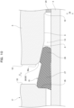
- the first protrusion 33 is formed further inward than the bolt insertion holes 32 in the pipe diameter direction B. As illustrated in FIG. 1 and FIG. 9 , the other end part in the separation direction 25 of the base part 27 of the seal member 15 is fitted into the concave portion 35 of the gland 17.
- the bolt insertion holes 32 and the second protrusions 34 are formed at predetermined intervals, respectively, in the pipe circumference direction G.
- the second protrusions 34 are formed further outward than the bolt insertion holes 32 in the pipe diameter direction B.
- a height h1 of the first protrusion 33 is the same as a height h2 of the second protrusions 34.
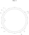
- a plurality of outer circumferential concave portions 37 which are recessed inwardly in the pipe diameter direction B are formed in the outer circumferential edge of the gland 17. As illustrated in FIG. 3 and FIG. 4 , each outer circumferential concave portion 37 enters between one bolt insertion hole 32 and an adjacent bolt insertion hole 32 from the outer circumferential edge of the gland 17.
- a width W1 in the pipe diameter direction B from the inner circumference to the outer circumference of the first protrusion 33 is configured to be equal to or greater than a width W2 in the pipe diameter direction B from the outer circumference of the first protrusion 33 to the outer circumferential concave portion 37.
- An inner circumferential surface 33a of the first protrusion 33 of the gland 17 is a tapered surface that increases in diameter progressively in the insertion direction C. As illustrated in FIG. 2 , a diameter D2 of an end part 30a of the second tapered surface 30 on the opening end face 16 side of the socket 5 is smaller than an internal diameter D1 of the first protrusion 33 of the gland 17.
- a clearance 39 that is surrounded by the inner circumferential surface 33a of the first protrusion 33, the second tapered surface 30, and the outer circumferential surface of the base part 27 of the seal member 15 is formed throughout the entire circumference.
- a bulb center part 41 of the bulb part 26 of the seal member 15 is located further inward in the pipe diameter direction B than the end part 30a of the second tapered surface 30 on the opening end face 16 side of the socket 5.
- the bulb center part 41 is a central portion between the inner circumference and outer circumference in the pipe diameter direction B of the bulb part 26.
- the lock ring 22 is accommodated in the lock ring accommodating groove 11, and the diameter of the lock ring 22 is expanded by enlarging the width of the cut portion of the lock ring 22 using a diameter expander (not illustrated in the drawings).
- the spigot 3 of the one pipe 2 is inserted into the socket 5 of the other pipe 4.
- the spigot protrusion 23 passes through the inner circumference of the lock ring 22 from the opening end face 16 of the socket 5, and reaches a position which is further toward the back side of the socket 5 than the lock ring 22.
- the lock ring 22 decreases in diameter and presses against the outer circumference of the spigot 3.
- the centering ring 24 is caused to slide in the pipe axis direction E, and enters between the inner circumference of the socket protrusion 10 and the outer circumference of the spigot 3.
- the spigot 3 is centered with respect to the socket 5, and a deviation between the central axis of the one pipe 2 and the central axis of the other pipe 4 substantially disappears.
- the other end part in the separation direction 25 of the base part 27 of the seal member 15 is fitted into the concave portion 35 of the gland 17, the T-head bolts 19 are inserted through the bolt holes 21 of the socket 5 and the bolt insertion holes 32 of the gland 17, and the nuts 20 are tightened onto the T-head bolts 19, and thereby the seal member 15 is pressed into the seal member insertion space 14 from the opening end face 16 of the socket 5 by the gland 17.
- the bulb part 26 of the seal member 15 is guided from the opening end face 16 of the socket 5 into the seal member insertion space 14 by the second tapered surface 30 of the guide part 29.
- the bulb center part 41 of the seal member 15 is located further inward in the pipe diameter direction B than the end part 30a of the second tapered surface 30, in a case where the T-head bolts 19 and the nuts 20 are unevenly tightened in sequence from those bolts and nuts at the top to those bolts and nuts at the bottom when attaching the gland 17 to the socket 5, even if the seal member 15 stretches and slackens, the bulb part 26 is reliably guided from the opening end face 16 of the socket 5 into the seal member insertion space 14 by the second tapered surface 30 of the guide part 29, and the seal member 15 can be reliably pressed into the seal member insertion space 14 by the gland 17.
- the seal member 15 when the seal member 15 is pressed into the seal member insertion space 14 by the gland 17, because the other end part of the seal member 15 is fitted into the concave portion 35 of the gland 17, the other end part of the seal member 15 can be prevented from becoming misaligned and turning over in the pipe diameter direction B.
- the weight of the gland 17 can be reduced in comparison to a gland in which the outer circumferential concave portions 37 are not formed.
- the gland 17 is configured so that the width W1 from the inner circumference to the outer circumference of the first protrusion 33 is equal to or greater than the width W2 from the outer circumference of the first protrusion 33 to the outer circumferential concave portions 37, the strength of the gland 17 can be sufficiently maintained even when the plurality of outer circumferential concave portions 37 are formed in the outer circumferential edge of the gland 17.
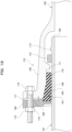
- the one pipe 2 is joined in a straight fashion without bending to the other pipe 4, in a second embodiment that is described hereunder, as illustrated in FIG. 12 and FIG. 13 , the one pipe 2 may be joined to the other pipe 4 in a state in which the one pipe 2 is bent at a predetermined bending angle ⁇ . At such time, the one pipe 2 inclines so that the end part on the spigot 3 side is at a higher position than the end part on the opposite side.
- the structure of the pipe joint 1 that joins together the pipes 2 and 4 bent in this manner is the same as the structure of the pipe joint 1 in the first embodiment that is described above (see FIG. 1 ).
- the bulb part 26 of the seal member 15 is guided from the opening end face 16 of the socket 5 into the seal member insertion space 14 by the second tapered surface 30 of the guide part 29.
- the bulb center part 41 of the seal member 15 is located further inward in the pipe diameter direction B than the end part 30a of the second tapered surface 30, the bulb part 26 is reliably guided from the opening end face 16 of the socket 5 into the seal member insertion space 14 by the second tapered surface 30 of the guide part 29, and the seal member 15 can be reliably pressed into the seal member insertion space 14 by the gland 17.
Landscapes
- Engineering & Computer Science (AREA)
- General Engineering & Computer Science (AREA)
- Mechanical Engineering (AREA)
- Joints With Sleeves (AREA)
- Joints Allowing Movement (AREA)
- Joints With Pressure Members (AREA)
Applications Claiming Priority (2)
| Application Number | Priority Date | Filing Date | Title |
|---|---|---|---|
| JP2020185472A JP7602894B2 (ja) | 2020-11-06 | 2020-11-06 | 管継手、押輪および管の接合方法 |
| PCT/JP2021/040119 WO2022097585A1 (fr) | 2020-11-06 | 2021-10-29 | Joint de tuyau et procédé pour assembler un anneau de pression et un tuyau |
Publications (2)
| Publication Number | Publication Date |
|---|---|
| EP4239237A1 true EP4239237A1 (fr) | 2023-09-06 |
| EP4239237A4 EP4239237A4 (fr) | 2024-05-22 |
Family
ID=81457924
Family Applications (1)
| Application Number | Title | Priority Date | Filing Date |
|---|---|---|---|
| EP21889138.0A Pending EP4239237A4 (fr) | 2020-11-06 | 2021-10-29 | Joint de tuyau et procédé pour assembler un anneau de pression et un tuyau |
Country Status (8)
| Country | Link |
|---|---|
| US (1) | US12442472B2 (fr) |
| EP (1) | EP4239237A4 (fr) |
| JP (1) | JP7602894B2 (fr) |
| CN (1) | CN116490712B (fr) |
| CA (1) | CA3196194A1 (fr) |
| SA (1) | SA523440703B1 (fr) |
| TW (1) | TWI910260B (fr) |
| WO (1) | WO2022097585A1 (fr) |
Families Citing this family (1)
| Publication number | Priority date | Publication date | Assignee | Title |
|---|---|---|---|---|
| JP2024006137A (ja) | 2022-07-01 | 2024-01-17 | 株式会社クボタ | 管継手 |
Family Cites Families (21)
| Publication number | Priority date | Publication date | Assignee | Title |
|---|---|---|---|---|
| US3941410A (en) * | 1974-10-10 | 1976-03-02 | Tadashi Miyaoka | Pipe joint construction |
| JPS59217090A (ja) * | 1983-05-23 | 1984-12-07 | 大阪瓦斯株式会社 | ソケット管継手の漏洩修繕工法 |
| JPH0643470U (ja) * | 1992-11-13 | 1994-06-10 | 三菱樹脂株式会社 | シールパッキン |
| JP3553713B2 (ja) * | 1995-11-27 | 2004-08-11 | 株式会社水研 | 流体管のシール構造 |
| JP2003222276A (ja) | 2002-01-30 | 2003-08-08 | Kubota Corp | 管の継手構造 |
| US7354073B2 (en) | 2004-03-30 | 2008-04-08 | Waterworks Technology Development Organization, Co., Ltd. | Pipe joint |
| CN103148293B (zh) * | 2009-01-27 | 2015-07-29 | 株式会社久保田 | 管接头 |
| JP5455383B2 (ja) * | 2009-01-27 | 2014-03-26 | 株式会社クボタ | 管継手 |
| JP5455381B2 (ja) * | 2009-01-27 | 2014-03-26 | 株式会社クボタ | シール材 |
| JP5570173B2 (ja) * | 2009-10-08 | 2014-08-13 | 株式会社クボタ | スペーサおよび管 |
| JP5451275B2 (ja) | 2009-05-13 | 2014-03-26 | 株式会社クボタ | 管継手 |
| JP2011085162A (ja) * | 2009-10-14 | 2011-04-28 | Kubota Corp | 管継手 |
| JP2011099515A (ja) * | 2009-11-06 | 2011-05-19 | Kubota Corp | 弁と管との継手構造および弁 |
| JP5665801B2 (ja) | 2012-06-25 | 2015-02-04 | 株式会社クボタ | 押輪および継手および弁 |
| MY176920A (en) * | 2012-06-25 | 2020-08-26 | Kubota Kk | Sealing material, pressing ring, joint, and valve |
| JP5870158B2 (ja) * | 2014-06-13 | 2016-02-24 | 株式会社クボタ | 管路構造および管路構造用プログラム |
| JP6735123B2 (ja) | 2016-03-28 | 2020-08-05 | 株式会社クボタ | 管継手および管の接合方法 |
| JP6764668B2 (ja) * | 2016-03-28 | 2020-10-07 | 株式会社クボタ | 管継手および管の接合方法 |
| CN108884955B (zh) * | 2016-03-28 | 2020-07-03 | 株式会社久保田 | 管接头、脱离防止构件、及管接合方法 |
| JP7133464B2 (ja) * | 2018-12-27 | 2022-09-08 | 株式会社クボタ | 管接合用心出し装置およびスペーサ |
| JP7382203B2 (ja) * | 2019-10-18 | 2023-11-16 | 株式会社クボタ | 管継手および管の接合方法 |
-
2020
- 2020-11-06 JP JP2020185472A patent/JP7602894B2/ja active Active
-
2021
- 2021-10-29 EP EP21889138.0A patent/EP4239237A4/fr active Pending
- 2021-10-29 US US18/034,968 patent/US12442472B2/en active Active
- 2021-10-29 CN CN202180073965.1A patent/CN116490712B/zh active Active
- 2021-10-29 WO PCT/JP2021/040119 patent/WO2022097585A1/fr not_active Ceased
- 2021-10-29 CA CA3196194A patent/CA3196194A1/fr active Pending
- 2021-11-04 TW TW110141158A patent/TWI910260B/zh active
-
2023
- 2023-05-04 SA SA523440703A patent/SA523440703B1/ar unknown
Also Published As
| Publication number | Publication date |
|---|---|
| SA523440703B1 (ar) | 2024-08-05 |
| TW202316053A (zh) | 2023-04-16 |
| CN116490712A (zh) | 2023-07-25 |
| JP7602894B2 (ja) | 2024-12-19 |
| CA3196194A1 (fr) | 2022-05-12 |
| US12442472B2 (en) | 2025-10-14 |
| JP2022074980A (ja) | 2022-05-18 |
| CN116490712B (zh) | 2026-01-27 |
| EP4239237A4 (fr) | 2024-05-22 |
| US20230400128A1 (en) | 2023-12-14 |
| TWI910260B (zh) | 2026-01-01 |
| WO2022097585A1 (fr) | 2022-05-12 |
Similar Documents
| Publication | Publication Date | Title |
|---|---|---|
| US11125369B2 (en) | Coupling having tabbed retainer | |
| US6880864B2 (en) | Tube joint with attachment and detachment mechanism | |
| EP4043772B1 (fr) | Joint de tuyau, méthode pour joindre des tuyaux et utilisation d'un corps de bague dans un joint de tuyau | |
| EP4043771B1 (fr) | Raccord de tuyau | |
| US12442472B2 (en) | Pipe joint, gland, and method for joining pipes | |
| US20250224054A1 (en) | Gland, pipe joint, and method for joining pipes | |
| CN118119786A (zh) | 压环、管接头以及管的接合方法 | |
| EP4524444A1 (fr) | Corps de bague, joint de tuyau et procédé pour raccorder des tuyaux à l'aide dudit corps de bague | |
| US12359755B2 (en) | Pipe joint, spacer provided in pipe joint, and dividing piece constituting spacer | |
| US20220235805A1 (en) | Functional Element, Component Assembly and Method of Manufacturing a Component Assembly | |
| JP7702313B2 (ja) | 押輪、管継手および管の接合方法 |
Legal Events
| Date | Code | Title | Description |
|---|---|---|---|
| STAA | Information on the status of an ep patent application or granted ep patent |
Free format text: STATUS: THE INTERNATIONAL PUBLICATION HAS BEEN MADE |
|
| PUAI | Public reference made under article 153(3) epc to a published international application that has entered the european phase |
Free format text: ORIGINAL CODE: 0009012 |
|
| STAA | Information on the status of an ep patent application or granted ep patent |
Free format text: STATUS: REQUEST FOR EXAMINATION WAS MADE |
|
| 17P | Request for examination filed |
Effective date: 20230602 |
|
| AK | Designated contracting states |
Kind code of ref document: A1 Designated state(s): AL AT BE BG CH CY CZ DE DK EE ES FI FR GB GR HR HU IE IS IT LI LT LU LV MC MK MT NL NO PL PT RO RS SE SI SK SM TR |
|
| DAV | Request for validation of the european patent (deleted) | ||
| DAX | Request for extension of the european patent (deleted) | ||
| A4 | Supplementary search report drawn up and despatched |
Effective date: 20240422 |
|
| RIC1 | Information provided on ipc code assigned before grant |
Ipc: F16L 21/08 20060101ALI20240416BHEP Ipc: F16L 37/088 20060101ALI20240416BHEP Ipc: F16L 21/04 20060101AFI20240416BHEP |
|
| RAP3 | Party data changed (applicant data changed or rights of an application transferred) |
Owner name: KUBOTA CORPORATION |
|
| STAA | Information on the status of an ep patent application or granted ep patent |
Free format text: STATUS: EXAMINATION IS IN PROGRESS |
|
| 17Q | First examination report despatched |
Effective date: 20250821 |