EP4240531B1 - Croix d'appui pour un hachoir à viande - Google Patents
Croix d'appui pour un hachoir à viande Download PDFInfo
- Publication number
- EP4240531B1 EP4240531B1 EP21805943.4A EP21805943A EP4240531B1 EP 4240531 B1 EP4240531 B1 EP 4240531B1 EP 21805943 A EP21805943 A EP 21805943A EP 4240531 B1 EP4240531 B1 EP 4240531B1
- Authority
- EP
- European Patent Office
- Prior art keywords
- hub
- cross
- support cross
- noses
- shaped support
- Prior art date
- Legal status (The legal status is an assumption and is not a legal conclusion. Google has not performed a legal analysis and makes no representation as to the accuracy of the status listed.)
- Active
Links
Images

Classifications
-
- B—PERFORMING OPERATIONS; TRANSPORTING
- B02—CRUSHING, PULVERISING, OR DISINTEGRATING; PREPARATORY TREATMENT OF GRAIN FOR MILLING
- B02C—CRUSHING, PULVERISING, OR DISINTEGRATING IN GENERAL; MILLING GRAIN
- B02C18/00—Disintegrating by knives or other cutting or tearing members which chop material into fragments
- B02C18/30—Mincing machines with perforated discs and feeding worms
- B02C18/301—Mincing machines with perforated discs and feeding worms with horizontal axis
- B02C18/302—Mincing machines with perforated discs and feeding worms with horizontal axis with a knife-perforated disc unit
-
- B—PERFORMING OPERATIONS; TRANSPORTING
- B02—CRUSHING, PULVERISING, OR DISINTEGRATING; PREPARATORY TREATMENT OF GRAIN FOR MILLING
- B02C—CRUSHING, PULVERISING, OR DISINTEGRATING IN GENERAL; MILLING GRAIN
- B02C18/00—Disintegrating by knives or other cutting or tearing members which chop material into fragments
- B02C18/30—Mincing machines with perforated discs and feeding worms
- B02C18/305—Details
Definitions
- the invention relates to a support cross for a meat grinder.
- Meat grinders generally use a multi-part cutting set that cuts the material to be cut up, which is fed in via a working screw, to the desired size in several cutting steps, for example using a pre-cutter, one or more knives and perforated disks.
- the last element of such a cutting set is usually a support cross.
- the knives are mounted on a drivable, rotating knife pin, so that they rotate together with the knife pin.
- they have a central shaped recess adapted to the cross-section of the knife pin.
- the pre-cutter, the perforated disks and the support cross are arranged in the housing of the meat grinder in a rotationally fixed manner and have a central hole for the knife pin.
- the knife pin is connected to the conveyor screw at one end in a rotationally fixed manner and has an axially extending support section starting from the connection point with the conveyor screw on which the knives are mounted.
- the knife pin is inserted with its one end, the insertion end, into the bearing bore of the conveyor screw.
- the fastening ring which is pushed onto the knife pin and rests against the stop surface of the knife pin, is then connected to the conveyor screw.
- This connection is a detachable connection.
- recesses 21 are provided on the fastening ring to make it easier to loosen the screw connection, see Fig. 2 , or notches 22, see Fig. 4 , which provide access for suitable tools when loosening the screw connection.
- the object of the present invention was to simplify the assembly or disassembly of the known knife pins.
- a new support cross is proposed for a meat grinder, which in a known manner comprises a hub with a central bore, an outer ring and several webs which extend between the hub and the outer ring. There is a groove on the outside of the outer ring for the rotationally fixed mounting of the support cross in the meat grinder.
- this support cross has a tool function. In the area of the hub there are one or more elements which have a tool function.
- such elements are present as lugs on one end of the hub. These elements can serve as engagement elements, for example, when dismantling the knife pin.
- the lugs protrude from the end of the hub, i.e. from the front or back of the support cross.
- the arrangement of the lugs is important.
- the fastening ring After removing the cutting elements from the meat grinder, the fastening ring must be loosened in order to dismantle the knife pin described above.
- This fastening ring holds the knife pin in the conveyor screw.
- the support cross is pushed onto the knife pin and turned so that the lugs on the support cross are aligned with corresponding recesses or notches in the fastening ring.
- the support cross is pressed onto the fastening ring, and the lugs engage in the recesses or notches in the fastening ring.
- the fastening ring can now be loosened by turning the support cross.
- the new support cross braces the elements of the cutting set in the housing of the meat grinder in a known manner together with a locking nut.
- the new support cross has an additional function, namely a tool function. In one embodiment of the invention, it can serve as an assembly or disassembly tool for the knife pin.
- no additional tools are required for assembling and disassembling the knife pin.
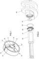
- the support cross 10 shown in the figures is the last element of a cutting set in the meat grinder.
- This support cross 10 has in Fig. 1 three webs 12, which connect an outer ring 13 and a central hub 11.
- a central bore 15 is provided in the hub 11.
- the knife pin 30, shown in Fig. 2 rotatably mounted.
- the hub 11 has two lugs 16, 16' on its front surface.
- a groove 14 is provided on the outer ring 13, which interacts with a corresponding key on the housing wall of the meat grinder and thus prevents a rotational movement of the support cross 10 during the shredding process.
- the key is removed and a rotational movement of the support cross is possible.
- Fig. 2 shows the conveyor screw 40, the knife pin 30 and the fastening ring 20 used to connect the knife pin 30 to the conveyor screw 40.
- two sealing rings 50, 51 are provided in this embodiment.
- the knife pin 30 is inserted into the conveyor screw 40 at one end.
- Fastening ring 20, which has a suitable thread for a screw connection to the conveyor screw 40, is pushed over the knife pin 30.
- the support cross 10 is then pushed over the narrower part of the knife pin 30 and the support cross 10 is aligned so that the two lugs 16, 16' can engage in the two recesses 21. If the support cross 10 is pressed tightly against the fastening ring 20, the support cross 10 can be rotated.
- the webs 12 of the support cross provide a handle for this.
- the rotary movement of the support cross 10 is transmitted to the fastening ring 20 by the engagement of the lugs 16, 16' in the recesses 21, thus tightening the screw connection to the conveyor screw 40.
- the knife pin 30 is also dismantled using the support cross 10. An additional tool is therefore not required.
- lugs 16, 16' diametrically opposite each other on the front side of the hub 11.
- the lugs 16, 16' are located on the outer edge of the hub 11. This arrangement has been chosen so that the lugs 16, 16' fit into the edge notches 22 of the fastening ring 20', shown in Fig. 4 , The assembly and disassembly process of the knife pin 30 using the support cross 10 from Fig. 3 is done as described in the previous example.
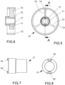
- the support cross 10 has a bearing bush 17 accommodated in the central bore 15.
- Such bearing bushes 17 are used in support crosses and cutting elements of the meat grinder so that after a certain period of operation only the bearing bush has to be replaced and not the support cross or cutting element.
- the two lugs 16, 16' are located diametrically opposite each other on the front of the bearing bush 17.
- the lugs 16, 16' protrude from the front.
- the lugs 16, 16' are provided on the outer edge of the bearing bush 17, see Fig. 8 .
- the bearing bush 17 has an inner bore in which the knife pin 30, shown in Fig. 2 , can be mounted in a rotatable manner.
- the bearing bush 17 has a front area of larger outer diameter - left side in Fig. 7 and a rear area with smaller outer diameter - right side in Fig. 7 .
- the hub 11 of the support cross 10 has a central bore 15 with two areas, each of which has a different inner diameter, so that a step is formed.
- the assembly and disassembly process of the knife pin 30 with the help of this support cross 10 from Fig. 5 is carried out as already described.
- the step inside the hub 11 prevents the bearing bush 17 from being pushed backwards through the central hole 15 during assembly or disassembly. It forms a stop area for the front area of the bearing bush 17.
- the front area of larger outer diameter is also designed as a ring, but the rear area has a shape that differs from a round ring, for example, it has an oval circumference in cross-section.
Landscapes
- Engineering & Computer Science (AREA)
- Food Science & Technology (AREA)
- Crushing And Pulverization Processes (AREA)
Claims (5)
- Croix d'appui pour un hachoir à viande,- comprenant un moyeu (11) avec alésage central (15), un anneau extérieur (13) et plusieurs nervures (12) qui s'étendent entre le moyeu (11) et l'anneau extérieur (13),- avec une gorge (14) contre le côté extérieur de l'anneau extérieur (13) pour former un appui l'empêchant de tourner dans le hachoir à viande,
caractérisée en ce que- dans la zone du moyeu (11) sont présents un ou plusieurs éléments (16, 16') qui possèdent une fonction d'outil,- à savoir, contre un côté frontal du moyeu (11) sont disposés un ou plusieurs ergots (16, 16') qui font saillie depuis le côté frontal ou,- dans l'alésage central (15) du moyeu (11) est maintenue une douille palier (17) qui sur son côté avant possède un ou plusieurs ergots (16, 16') faisant saillie depuis le côté avant. - Croix d'appui selon la revendication 1, caractérisée en ce que deux ergots (16, 16') sont disposés diamétralement opposés sur le côté frontal.
- Croix d'appui selon la revendication 1 ou 2, caractérisé en ce que les ergots (16, 16') faisant saillie se trouvent contre le bord extérieur du moyeu (11) ou de la douille palier (17).
- Croix d'appui selon la revendication 1, caractérisée en ce que la douille palier (17) possède deux zones de diamètres extérieurs différents, à savoir une zone avant d'un plus grand diamètre extérieur, et sachant que l'alésage central (15) du moyeu (11) présente un gradin correspondant pour cette douille palier (17).
- Croix d'appui selon l'une des revendications 1 à 4, caractérisée en ce que la zone arrière présente une forme différente de celle d'un anneau rond, par exemple qu'elle possède une ligne périphérique de section ovale.
Applications Claiming Priority (2)
| Application Number | Priority Date | Filing Date | Title |
|---|---|---|---|
| DE202020106351.0U DE202020106351U1 (de) | 2020-11-05 | 2020-11-05 | Stützkreuz für einen Fleischwolf |
| PCT/EP2021/080606 WO2022096556A1 (fr) | 2020-11-05 | 2021-11-04 | Support en forme de croix pour hachoir à viande |
Publications (3)
| Publication Number | Publication Date |
|---|---|
| EP4240531A1 EP4240531A1 (fr) | 2023-09-13 |
| EP4240531B1 true EP4240531B1 (fr) | 2024-12-04 |
| EP4240531C0 EP4240531C0 (fr) | 2024-12-04 |
Family
ID=73747782
Family Applications (1)
| Application Number | Title | Priority Date | Filing Date |
|---|---|---|---|
| EP21805943.4A Active EP4240531B1 (fr) | 2020-11-05 | 2021-11-04 | Croix d'appui pour un hachoir à viande |
Country Status (6)
| Country | Link |
|---|---|
| US (1) | US11969736B2 (fr) |
| EP (1) | EP4240531B1 (fr) |
| DE (1) | DE202020106351U1 (fr) |
| ES (1) | ES3008942T3 (fr) |
| PL (1) | PL4240531T3 (fr) |
| WO (1) | WO2022096556A1 (fr) |
Families Citing this family (4)
| Publication number | Priority date | Publication date | Assignee | Title |
|---|---|---|---|---|
| DE202020106351U1 (de) | 2020-11-05 | 2020-11-19 | Lumbeck & Wolter GmbH. & Co. KG. | Stützkreuz für einen Fleischwolf |
| DE102021119200B4 (de) | 2021-07-23 | 2026-04-02 | Kutter- und Gerätebau Wetter GmbH | Förderschneckenvorrichtung mit demontierbarem Zapfen und Fleischwolf hiermit |
| DE102021132411A1 (de) | 2021-12-09 | 2023-06-15 | Albert Handtmann Maschinenfabrik Gmbh & Co. Kg | Stützkreuz |
| US20230329484A1 (en) * | 2022-04-13 | 2023-10-19 | LEM Products Holdings, LLC | Dual grind adapter kit |
Family Cites Families (24)
| Publication number | Priority date | Publication date | Assignee | Title |
|---|---|---|---|---|
| US374568A (en) * | 1887-12-06 | Meat-cutter | ||
| US2459230A (en) * | 1944-12-08 | 1949-01-18 | Fred W Litten | Food chopper with rotary forcer screw |
| US3340917A (en) * | 1965-08-09 | 1967-09-12 | Mayer & Co Inc O | Comminuting machine |
| IT220009Z2 (it) | 1990-07-13 | 1993-06-03 | Risco Brevetti | "tritacarne a coclea con perfezionamento sistema di supporto della coclea |
| DE29610848U1 (de) * | 1996-06-20 | 1996-10-17 | WANNER-Technik GmbH, 97877 Wertheim | Feststoffmühle |
| US6449991B1 (en) | 2000-04-12 | 2002-09-17 | Sensormatic Electronics Corporation | One part theft deterrent device |
| US7540440B2 (en) * | 2005-10-20 | 2009-06-02 | Weiler And Company, Inc | Orifice plate removal system for an orifice plate of a grinding machine |
| EP1908898B1 (fr) | 2006-10-06 | 2017-12-20 | SimonsVoss Technologies GmbH | Bouton pour cylindre de serrure électronique |
| DE102007005214B3 (de) | 2007-01-29 | 2008-06-12 | Uhlmann, Günter | Elektromechanisches Schließsystem |
| ES2494851T3 (es) * | 2007-06-26 | 2014-09-16 | Weiler And Company, Inc. | Molino de bloques congelados |
| ITBO20130540A1 (it) * | 2013-10-02 | 2015-04-03 | Giorgio Leonardi | Macchina per tritare il cibo |
| DK177991B1 (en) | 2013-10-07 | 2015-02-16 | Poly Care Aps | Motorised door lock actuator |
| US9539580B2 (en) * | 2013-10-22 | 2017-01-10 | Rome, Ltd. | Feed screw for meat grinding reclamation system |
| GB2519536B (en) * | 2013-10-23 | 2017-09-06 | Kenwood Ltd | Foodstuff-grinding attachment for a kitchen machine |
| US20150196039A1 (en) * | 2014-01-13 | 2015-07-16 | Formtec, LLC, Spherical IP, LLC. | Grinder apparatus |
| DE102014216720A1 (de) * | 2014-08-22 | 2016-02-25 | Karl Schnell Gmbh & Co. Kg | Zerkleinerungsmaschine zur Zerkleinerung eines Produkts |
| DE202014104033U1 (de) | 2014-08-28 | 2014-09-08 | Lumbeck & Wolter Gmbh & Co. Kg | Schneidsatzelement |
| DE202016103109U1 (de) * | 2016-05-03 | 2017-08-07 | Lumbeck & Wolter Gmbh & Co. Kg | Schneideinrichtung, insbesondere für Fleischwölfe |
| DE102018202563B4 (de) | 2018-02-20 | 2024-06-13 | Simonsvoss Technologies Gmbh | Knauf für einen elektronischen Schließzylinder |
| JP7441227B2 (ja) * | 2018-12-21 | 2024-02-29 | マレル・サーモン・アクティエセルスカブ | 食品加工装置及び食品の加工方法 |
| KR102147343B1 (ko) | 2020-05-27 | 2020-08-24 | 주식회사 윈텍 | 서랍장용 지문인식 잠금장치 |
| DE202020105051U1 (de) | 2020-09-02 | 2020-09-08 | Lumbeck & Wolter GmbH. & Co. KG. | Fleischwolf |
| DE202020105052U1 (de) | 2020-09-02 | 2020-09-08 | Lumbeck & Wolter GmbH. & Co. KG. | Fleischwolf |
| DE202020106351U1 (de) | 2020-11-05 | 2020-11-19 | Lumbeck & Wolter GmbH. & Co. KG. | Stützkreuz für einen Fleischwolf |
-
2020
- 2020-11-05 DE DE202020106351.0U patent/DE202020106351U1/de active Active
-
2021
- 2021-11-04 WO PCT/EP2021/080606 patent/WO2022096556A1/fr not_active Ceased
- 2021-11-04 PL PL21805943.4T patent/PL4240531T3/pl unknown
- 2021-11-04 US US18/245,444 patent/US11969736B2/en active Active
- 2021-11-04 ES ES21805943T patent/ES3008942T3/es active Active
- 2021-11-04 EP EP21805943.4A patent/EP4240531B1/fr active Active
Also Published As
| Publication number | Publication date |
|---|---|
| EP4240531A1 (fr) | 2023-09-13 |
| ES3008942T3 (en) | 2025-03-25 |
| PL4240531T3 (pl) | 2025-04-14 |
| WO2022096556A1 (fr) | 2022-05-12 |
| US20230381789A1 (en) | 2023-11-30 |
| US11969736B2 (en) | 2024-04-30 |
| DE202020106351U1 (de) | 2020-11-19 |
| EP4240531C0 (fr) | 2024-12-04 |
Similar Documents
| Publication | Publication Date | Title |
|---|---|---|
| EP4240531B1 (fr) | Croix d'appui pour un hachoir à viande | |
| EP3964295B3 (fr) | Hachoir à viande | |
| WO2022049111A1 (fr) | Hachoir à viande | |
| EP1570719B1 (fr) | Appareil de coupage, en particulier tondeuse â gazon | |
| EP2233260B1 (fr) | Dispositif de broyage de bois | |
| EP1082173B1 (fr) | Hache-viande pour hacher de la viande fraiche et de la viande congelee | |
| EP1353754A1 (fr) | Systeme de fleau | |
| EP4146399B1 (fr) | Système de jeu à couper pour un hachoir à viande | |
| DE202015107131U1 (de) | Werkzeugbaugruppe für eine Zerkleinerungsvorrichtung | |
| DE202008018379U1 (de) | Mähvorrichtung für Erntegut | |
| EP4076114B1 (fr) | Broyeur, disque de broyage pour un broyeur et machine à café équipée d'un tel broyeur | |
| DE4431960C1 (de) | Messer für Fleischwölfe | |
| EP2311568B1 (fr) | Ensemble de coupe doté d'un compteur de bague d'écartement de sécurité | |
| EP2845649A1 (fr) | Dispositif de découpe | |
| EP3323572B1 (fr) | Dechiqueteuse | |
| DE2031635A1 (de) | Schneidscheibe fur eine Schnitzel maschine | |
| EP2474256B1 (fr) | Moulin à épices doté d'un broyeur | |
| DE102012106188B4 (de) | Verfahren zum Demontieren und Verfahren zum Montieren eines Schneidwerkzeugs einer Werkzeuganordnung zum Herstellen von Wandschlitzen | |
| EP1196244A1 (fr) | Machine pour broyer une matiere coupee organique | |
| CH254605A (de) | Fräser für Holzbearbeitung. | |
| EP0987201B1 (fr) | Lame de coupe pour vis mélangeuse, particulièrement dans une remorque mélangeuse de fourage | |
| DE4337157A1 (de) | Vorrichtung zum Vorzerkleinern von Abfällen | |
| WO2025171965A1 (fr) | Outil de coupe, en particulier cisailles ou ciseaux, à lames élastiquement précontraintes l'une par rapport à l'autre | |
| DE1055989B (de) | Messeranordnung fuer Fleischzerkleinerungsmaschinen | |
| DE102004026331A1 (de) | Vorrichtung zur Halterung von Kuttermessern |
Legal Events
| Date | Code | Title | Description |
|---|---|---|---|
| STAA | Information on the status of an ep patent application or granted ep patent |
Free format text: STATUS: UNKNOWN |
|
| STAA | Information on the status of an ep patent application or granted ep patent |
Free format text: STATUS: THE INTERNATIONAL PUBLICATION HAS BEEN MADE |
|
| PUAI | Public reference made under article 153(3) epc to a published international application that has entered the european phase |
Free format text: ORIGINAL CODE: 0009012 |
|
| STAA | Information on the status of an ep patent application or granted ep patent |
Free format text: STATUS: REQUEST FOR EXAMINATION WAS MADE |
|
| 17P | Request for examination filed |
Effective date: 20230315 |
|
| AK | Designated contracting states |
Kind code of ref document: A1 Designated state(s): AL AT BE BG CH CY CZ DE DK EE ES FI FR GB GR HR HU IE IS IT LI LT LU LV MC MK MT NL NO PL PT RO RS SE SI SK SM TR |
|
| DAV | Request for validation of the european patent (deleted) | ||
| DAX | Request for extension of the european patent (deleted) | ||
| GRAP | Despatch of communication of intention to grant a patent |
Free format text: ORIGINAL CODE: EPIDOSNIGR1 |
|
| STAA | Information on the status of an ep patent application or granted ep patent |
Free format text: STATUS: GRANT OF PATENT IS INTENDED |
|
| INTG | Intention to grant announced |
Effective date: 20240627 |
|
| GRAS | Grant fee paid |
Free format text: ORIGINAL CODE: EPIDOSNIGR3 |
|
| GRAA | (expected) grant |
Free format text: ORIGINAL CODE: 0009210 |
|
| STAA | Information on the status of an ep patent application or granted ep patent |
Free format text: STATUS: THE PATENT HAS BEEN GRANTED |
|
| AK | Designated contracting states |
Kind code of ref document: B1 Designated state(s): AL AT BE BG CH CY CZ DE DK EE ES FI FR GB GR HR HU IE IS IT LI LT LU LV MC MK MT NL NO PL PT RO RS SE SI SK SM TR |
|
| REG | Reference to a national code |
Ref country code: CH Ref legal event code: EP |
|
| REG | Reference to a national code |
Ref country code: DE Ref legal event code: R096 Ref document number: 502021006043 Country of ref document: DE |
|
| REG | Reference to a national code |
Ref country code: IE Ref legal event code: FG4D Free format text: LANGUAGE OF EP DOCUMENT: GERMAN |
|
| U01 | Request for unitary effect filed |
Effective date: 20241204 |
|
| U07 | Unitary effect registered |
Designated state(s): AT BE BG DE DK EE FI FR IT LT LU LV MT NL PT RO SE SI Effective date: 20241211 |
|
| REG | Reference to a national code |
Ref country code: ES Ref legal event code: FG2A Ref document number: 3008942 Country of ref document: ES Kind code of ref document: T3 Effective date: 20250325 |
|
| U1N | Appointed representative for the unitary patent procedure changed after the registration of the unitary effect |
Representative=s name: KOHLSTEDDE, EVA; DE |
|
| PG25 | Lapsed in a contracting state [announced via postgrant information from national office to epo] |
Ref country code: HR Free format text: LAPSE BECAUSE OF FAILURE TO SUBMIT A TRANSLATION OF THE DESCRIPTION OR TO PAY THE FEE WITHIN THE PRESCRIBED TIME-LIMIT Effective date: 20241204 |
|
| PG25 | Lapsed in a contracting state [announced via postgrant information from national office to epo] |
Ref country code: NO Free format text: LAPSE BECAUSE OF FAILURE TO SUBMIT A TRANSLATION OF THE DESCRIPTION OR TO PAY THE FEE WITHIN THE PRESCRIBED TIME-LIMIT Effective date: 20250304 |
|
| PG25 | Lapsed in a contracting state [announced via postgrant information from national office to epo] |
Ref country code: GR Free format text: LAPSE BECAUSE OF FAILURE TO SUBMIT A TRANSLATION OF THE DESCRIPTION OR TO PAY THE FEE WITHIN THE PRESCRIBED TIME-LIMIT Effective date: 20250305 |
|
| PG25 | Lapsed in a contracting state [announced via postgrant information from national office to epo] |
Ref country code: RS Free format text: LAPSE BECAUSE OF FAILURE TO SUBMIT A TRANSLATION OF THE DESCRIPTION OR TO PAY THE FEE WITHIN THE PRESCRIBED TIME-LIMIT Effective date: 20250304 |
|
| PG25 | Lapsed in a contracting state [announced via postgrant information from national office to epo] |
Ref country code: SM Free format text: LAPSE BECAUSE OF FAILURE TO SUBMIT A TRANSLATION OF THE DESCRIPTION OR TO PAY THE FEE WITHIN THE PRESCRIBED TIME-LIMIT Effective date: 20241204 |
|
| PG25 | Lapsed in a contracting state [announced via postgrant information from national office to epo] |
Ref country code: IS Free format text: LAPSE BECAUSE OF FAILURE TO SUBMIT A TRANSLATION OF THE DESCRIPTION OR TO PAY THE FEE WITHIN THE PRESCRIBED TIME-LIMIT Effective date: 20250404 |
|
| PG25 | Lapsed in a contracting state [announced via postgrant information from national office to epo] |
Ref country code: SK Free format text: LAPSE BECAUSE OF FAILURE TO SUBMIT A TRANSLATION OF THE DESCRIPTION OR TO PAY THE FEE WITHIN THE PRESCRIBED TIME-LIMIT Effective date: 20241204 |
|
| PG25 | Lapsed in a contracting state [announced via postgrant information from national office to epo] |
Ref country code: CZ Free format text: LAPSE BECAUSE OF FAILURE TO SUBMIT A TRANSLATION OF THE DESCRIPTION OR TO PAY THE FEE WITHIN THE PRESCRIBED TIME-LIMIT Effective date: 20241204 |
|
| PLBE | No opposition filed within time limit |
Free format text: ORIGINAL CODE: 0009261 |
|
| STAA | Information on the status of an ep patent application or granted ep patent |
Free format text: STATUS: NO OPPOSITION FILED WITHIN TIME LIMIT |
|
| 26N | No opposition filed |
Effective date: 20250905 |
|
| U20 | Renewal fee for the european patent with unitary effect paid |
Year of fee payment: 5 Effective date: 20251027 |
|
| PGFP | Annual fee paid to national office [announced via postgrant information from national office to epo] |
Ref country code: GB Payment date: 20251125 Year of fee payment: 5 |
|
| PGFP | Annual fee paid to national office [announced via postgrant information from national office to epo] |
Ref country code: PL Payment date: 20251001 Year of fee payment: 5 |
|
| PGFP | Annual fee paid to national office [announced via postgrant information from national office to epo] |
Ref country code: ES Payment date: 20251201 Year of fee payment: 5 |