EP4240909B1 - Traffic barrier, method for using a barrier, and barrier module - Google Patents
Traffic barrier, method for using a barrier, and barrier module Download PDFInfo
- Publication number
- EP4240909B1 EP4240909B1 EP21802842.1A EP21802842A EP4240909B1 EP 4240909 B1 EP4240909 B1 EP 4240909B1 EP 21802842 A EP21802842 A EP 21802842A EP 4240909 B1 EP4240909 B1 EP 4240909B1
- Authority
- EP
- European Patent Office
- Prior art keywords
- barrier
- module
- modules
- traffic
- drive
- Prior art date
- Legal status (The legal status is an assumption and is not a legal conclusion. Google has not performed a legal analysis and makes no representation as to the accuracy of the status listed.)
- Active
Links
Images











Classifications
-
- E—FIXED CONSTRUCTIONS
- E01—CONSTRUCTION OF ROADS, RAILWAYS, OR BRIDGES
- E01F—ADDITIONAL WORK, SUCH AS EQUIPPING ROADS OR THE CONSTRUCTION OF PLATFORMS, HELICOPTER LANDING STAGES, SIGNS, SNOW FENCES, OR THE LIKE
- E01F15/00—Safety arrangements for slowing, redirecting or stopping errant vehicles, e.g. guard posts or bollards; Arrangements for reducing damage to roadside structures due to vehicular impact
- E01F15/006—Lane control by movable lane separating barriers, e.g. shiftable barriers, retractable kerbs ; Apparatus or barriers specially adapted therefor, e.g. wheeled barriers
Definitions
- barrier modules need to be installed to extend the proximal end of the traffic barrier and/or barrier modules near the distal end should be removed. Or from the beginning longer lengths of barrier are installed, which leads to the phenomena that road works are only carried out at a small part of the total demarcated area. Resulting also in more and longer traffic nuisance. Often, this will require that at least one additional lane of the road has to be temporarily closed off, for instance by traffic cones. This will in particular be necessary in case the equipment can not be provided at the other lateral side of the barrier to be placed or to be removed. For instance, in case the barrier is placed on or near an outer edge of a shoulder of the road or near a median of the road, the equipment, for instance including heavy trucks for supplying or removing barrier modules, can usually not use the verge or a median strip.
- US2019/0301117A1 discloses a method of using a crash barrier comprising a series of crash barrier sections comprising a deflection body with at least one travelling gear that is movable between a standby position and a displacement position.
- the gear In the standby position the gear is retracted upward into a receptacle within the deflection body, and is moved out of said receptacle into the displacement position.
- the crash barrier section In the displacement position the crash barrier section can be moved over a road surface.
- the crash barrier section comprises a separate lifting device with which the crash barrier section has to be lifted and supported while the gear is moved from the standby position to the displacement position. This makes this known crash barrier complicated in both design and construction and in use. Moreover it limits the possible ways in how such crash barrier can be used.
- barrier module or modules By supporting the barrier module or modules on their drives only, contact between for example lower edges of the barrier body and the road surface is avoided, preventing damage of the road surface by such edges.
- Barrier modules of the disclosure can be coupled in a substantially longitudinal direction.
- the barrier formed by said modules can comprise a bend or curve, which can be maintained during movement of the barrier over said road surface.
- the barrier can for example be bent or curved around workers and/or equipment, protecting the workers and/or equipment from errant vehicles.
- the traffic barrier can thus be self-propelled by means of its own drives, moving the traffic barrier, in particular forward or rearward and/or sideways, for instance to relocate the traffic barrier along the road, can be done without using any external equipment and/or workers blocking an additional lane.
- the traffic barrier may be controlled by a person which is present at the location of the traffic barrier, and which may visually determine whether the traffic barrier moves as desired.
- the traffic barrier may for instance be provided with sensors and/or other equipment to perceive its surroundings, such as one or more cameras, GPS receivers, radar devices, LiDAR devices, sonar devices and/or odometry sensors, and/or other means which can facilitate self-driving.
- sensors and/or other equipment such as one or more cameras, GPS receivers, radar devices, LiDAR devices, sonar devices and/or odometry sensors, and/or other means which can facilitate self-driving.
- a traffic barrier moving along with road works will require fewer barrier modules, further reducing costs.
- the traffic barrier may alternatively, or additionally, for instance in order to form a back-up functionality, be provided with a lifting and lowering mechanism which can be hand operated.
- said traffic barrier may further be arranged for moving at least one of the barrier modules, and preferably at least a section comprising multiple barrier modules, more preferably substantially the entire traffic barrier, in a direction substantially transverse to the longitudinal direction of one or more of the barrier modules.
- Figure 1 shows two conventional temporary traffic barriers 101.
- the temporary traffic barriers 101 are temporary placed on the shoulders 120 of a road 121 on top of a dyke 122.
- the temporary traffic barriers 101 are installed to protect workers 123 from errant vehicles as the standard guiderails 124 have been removed locally in view of construction work to the dyke.
- the temporary traffic barriers 101 not only the emergency lane formed by the shoulder 120 is blocked by the temporary traffic barriers 101, but also an additional lane 125 of the road 121 is blocked by equipment 126 used for relocating modules 102 of the temporary traffic barrier 101.
- FIG 2 shows a schematic perspective view of a first embodiment of a traffic barrier 1 according to an aspect of the invention, which is formed as a self moving traffic barrier 1.
- the traffic barrier 1 is arranged and/or intended for protecting workers from errant vehicles and/or for rerouting traffic.
- the traffic barrier 1 forms a temporary traffic barrier, in particular a crash rated movable highway barrier.
- the traffic barrier may be shaped as a so-called Jersey barrier or Jersey wall or Jersey bump, or a variation thereof, such as for instance a so-called F-Shape barrier or a so-called Constant-slope barrier.
- the outer face of the barrier 1 can for instance define a lower section 11 having a relatively shallow slope 12, while an upper section 13 has a relatively steep slope 14.
- the relatively shallow slope 12 may for instance make an angle of about 45° - 65° with the horizontal plane, preferably an angle of about 50° - 60°, such as about 55°.
- the relatively steep slope 14 may for instance make an angle of about 75° - 90° with the horizontal plane, preferably an angle of about 80° - 88 °, such as about 84°.
- the traffic barrier 1 comprises multiple elongate barrier modules 2 which are connected to each other, preferably in a manner wherein two adjacent barrier modules can pivot with respect to each other to a certain amount, at least when the self moving traffic barrier 1 is being relocated or shifted from one location to another location.
- the barrier modules 2 are connected to each other via an intermediate barrier part 3, which here is formed by a carriage 9.
- the barrier modules 2 are connected directly to each other.
- the width of the barrier modules 2 may correspond with the height of a conventional barrier module 2 of a conventional temporary traffic barrier, and/or may for instance be at least about 45 cm, preferably being at least 50 cm, more preferably at least 55 cm, such as about 60 cm, for instance 58 cm or 61 cm, or even more, such as for instance about 80 cm or for instance 82 cm.
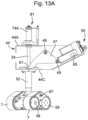
- the drive 5 can be or comprise an holonomic wheel, omni wheel, or Mecanum wheel based drive 5.
- each wheel 7 is provided with a series of rollers 7A provided at or forming the circumference of the wheel 7, which rollers 7A each have a rotational axis at an angle relative to the axis of the wheel 7, such that each wheel can move over a surface in all directions, as is known in the art.
- each wheel 7 is in fact a set of wheels.
- the wheels 7 are all driven by a motor 60 through a gear 61, such that they can be driven independently from each other, for changing drive directions D 5 of the drive 5.
- Such drive 5 can for example have three or more wheels 7.
- Obviously different types of these drives 5 can be combined in a barrier module 2 or barrier 1. With such drive 5 the drive 5 can move in any horizontal direction, without the necessity of rotating the carrier 53 of the drive 5.
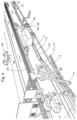
- the traffic barrier 1 may comprise carriages 9, that are arranged for moving at least one of the barrier modules 2, as for instance can be seen in the exemplary embodiment of Figure 3 .
- the carriage 9 may be formed as a built-in unit 8, which for instance may be built into a more or less standard barrier module, for instance a commercial off-the-shelf barrier module.
- Such carriage 9 can comprise a drive 5 as disclosed.
- the barrier 1 or barrier module 2 may comprise a battery 10, or other power source, which for instance may feed the actuator 6 of said drive 5.
- the power source may alternatively be located outside of the module 2.
- the traffic barrier 1 may be provided with one or more solar panels 33, which for instance may be used for recharging one or more batteries 10 of the traffic barrier.
- the solar panels 33 can be removable installed on a barrier module 2, for example after installing the traffic barrier 1 on its initial position.
- the solar panels 33 may be arranged such that they can form a fence 135 on top of the traffic barrier 1, for example hiding the construction work from view at least partly, thereby for instance counteracting that road users may be distracted by said construction work.
- These could also be different panels 135, preferably non-transparent panels.
- the barrier modules 2 may be provided with connectors 34, for instance formed by one or more receiving channels 34 or other apertures 34 or the like, which may be provided for instance at a top end of the barrier module 2.
- the rolling elements 7 can be driven by the drive 5.
- the traffic barrier 1 and/or one or more of the barrier modules 2 and/or other barrier parts may be arranged to be remotely controlled in a wireless manner
- the traffic barrier 1 and/or one or more of the barrier modules 2 and/or other barrier parts may, alternatively or additionally, be arranged to be remotely controlled in a wired manner.
- One, multiple or each barrier module 2 and/or other barrier part and/or the traffic barrier 1 may be provided with a wired remote control, which can be removably connectable thereto.
- the remote control may for instance be hand-held by a person, for instance a person walking along with the moving barrier 1.
- other embodiments are possible as well.
- the remote control may be part of and/or attached to a piece of working equipment, such as a mower, paver, asphalt cutter, etc., which may move along the road during the work.
- the barrier modules 2 or barrier 1 or the remote control 100 can comprise software for defining a route for the barrier modules 2 and/or barrier to follow.
- a control unit 17 or so-called controller may be used to control multiple drives and/or actuators, for instance also drives and/or actuators located in other barrier parts, e.g. in other carriages and/or in other barrier modules than the one in which said control unit or controller 17 is provided.
- the barrier may then comprise a main control unit 17 which, in particular based at least partly on remote control input data, may control locally provided secondary control units 17 that may locally control one or more drives or actuators, for instance at the barrier part where such secondary control unit 17 is provided.
- the lift module 43 engages a base frame 46 around the support 40.
- the lift module 43 comprises an arm 47, pivoting around a pivot axis 48, which here is shown extending substantially horizontally.
- One end 49 of the arm 47 is connected to a motor 50 and a second end 51 of the arm 47 engages the support 40.
- the motor 50 preferably is a linear motor, such as an electric motor, with which at least a pulling force F p can be exerted on the said end 49 of the arm.
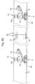
- each drive 5 is provided with a drive body 53 and a left side drive 56 and a right side drive 57.
- the left side drive 56 and right side drive 57 are positioned at opposite sides of an imaginary vertical center plane V, preferably a plane extending through the vertical axis X 40 of the support 40.
- Each of the left side drive 56 and right side drive 57 comprises a drive wheel 58A, B and a driven or idling wheel 59A, B, and a track 7 extending around the relevant drive wheel 58A, B and driven wheel 59A, B.
- Each drive wheel 58 A, B is connected to a motor such as an electric motor 61 through a gearing 62.
- the gearing 62 is preferably a reducing gearing, reducing the rotational speed of the drive wheel 58 relative to the axis of the motor 61 significantly, for example at a ratio of 20:1 or more, such as for example 40: 1, preferably at least 50:1, such as for example 100:1.
- Each side drive 56, 57 is furthermore provided with a track tensioner 67, for tensioning the track 7 around the wheels 58, 59.
- one or more guide rollers 68 can be provided between the wheels 58, 59 for supporting the track 60 further.
- the design of the drives 5, such as the gearing ratio, is preferably chosen such that the track 7 will not rotate the drive wheel 58 when the barrier module 2 is pushed near the relevant drive in a substantially horizontal direction, for example upon impact of a vehicle on the barrier module 2 in line with test protocols of NEN-EN-1317.
- the barrier will not roll away upon such impact and will perform in accordance with NEN-EN-1317 as a temporary traffic barrier, even when the traffic barrier 2 is supported on the road surface 35, 127 by the drives 5 only.
- This means that the lower edge 41 will be suspended above the road surface 35, 127 and the barrier module 2 cq barrier 1 can be moved over said road surface immediately by driving the motors 61.
- the height H of the barrier module body 2C can be adjusted using the lift mechanism but this is not necessary since the barrier 2 will rest on the surface by said drives 5.
- a drive unit as shown in fig. 14A having wheels 7 without tracks, or in fig. 14B , comprising omni directional wheels, can be designed to allow use of the barrier module 2 provided therewith, or at least a barrier provided with such modules, to be used as a barrier, conform said test protocols line NEN-EN-1317, without the lower edge or support elements of the barrier, other than the drives, having to be resting on the road.
- the drives are self-braking
- a brake 200 for use in a barrier 1 or barrier module 2 according to the disclosure can be a negative brake.
- the drive 5 is braked when the brake 200 is not powered, such as in a rest position.
- the brake 200 has to be powered, for example by an electrical current or mechanically, in order to release the brake 200 and allow the motor 61 to drive the relevant wheel 7 or wheels 7 or track 7.
- the substantially vertical support 40 is preferably fixedly connected to the base part 53 of the drive, between the left side drive 56 and the right side drive 57, central between the wheels 58, 59.
- the base part 53 with the tracks 7 can rotate the drive 5 easily relative to the barrier module 2 around the axis X 40 , substantially without drag of the tracks 7 over the surface.
- a barrier 1 formed with barrier modules 2 as described can be driven over a road surface 35 using the drives 5. Since the individual drives can be rotated around their respective vertical axis X 40 , the modules 2 and hence the barrier 1 can be driven in any direction and configuration, such as straight, bent, curved or hooked. Various modules 2 can be driven relative to other modules 2 in order to change their relative positions, especially angles ⁇ relative to each other, which can for example be defined as an angle ⁇ between their longitudinal direction D, as for example shown in top view in fig. 16 .
- the barrier modules are preferably coupled to each other by couplings 15 allowing some pivoting around a vertical axis, but preferably little longitudinal movement of one barrier module 2 relative to an adjacent module 2 coupled thereto.
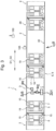
- the barrier module 2 can have at least one position sensor 82 near at least one longitudinal end 83 of the module 2, as for example shown in fig. 5 and 7A .
- at least one position sensor 82 is provided near each opposite longitudinal end 83, for defining a relative position of the barrier module 2 relative to a barrier module 2 coupled to said barrier module at said end 83.
- two position sensors 82 can be provided near each longitudinal end of a barrier module 2, one on either side of a vertical mid sectional longitudinal plane V D of the barrier module 2, as shown in fig. 7A .
- the distance measured between two sensors 82 at a first side of said vertical mid sectional longitudinal plane V D at mating ends 83 of the modules 2 will be the same as the distance measured between the two sensors 82 at the opposite side of said plane V D . If the longitudinal axis D are however at an angle ⁇ other than 0 or 180 degrees, the sets of sensors 82 on opposite sides of said plane V D will measure different distances between them. From the difference in distance the relative angle ⁇ between the connected barrier modules 2 can be calculated.
- the barrier module 2 is provided with at least one bar 84 extending in a longitudinal direction D1, D2 of the barrier module 2, at least from one longitudinal end 83 of the barrier module 2 towards a central portion of the module 2. More preferably the at least one bar extends from near one longitudinal end 83 of the module 2 to near the opposite longitudinal end 83 of the barrier module 2. The at least one and preferably each of the position sensors 82 can then be mounted to said at least one bar 84.
- the at least one bar 84 extends through the barrier module body 2C, spaced apart from the outer wall 2A of said body.
- the at least one bar 84 has substantially no constructional purpose for the barrier module 2 itself. This means that the impact resistance of the barrier module 2 can be substantially the same with or without said one or more bars 84.
- the bar or bars 84 in such embodiments serve the purpose of mounting the position sensors 82 near said end or ends 83 in a well defined position relative to each other, irrespective of for example deformations of the barrier outer wall 2A or for example bending or warping of the barrier module body 2C.
- Each module 2 can be provided with such set of a control unit 17, receiver 16 and/or transmitter 18, or a central set of such unit 17, receiver 16 and/or transmitter 18 can be provided.
- the control unit 17 preferably comprises an algorithm for control of the drives 5 at least in part based on said data received, such as data received from some or all of the sensors 81, 82, 85, and/or data received from external sources such as GPS coordinates, traffic and traffic intensities, drive plans, camera images from a camera 105 or 104 or the like.
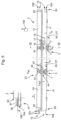
- Figure 4 shows a schematic perspective view of an embodiment of a traffic barrier 1 according to a further aspect of the invention.
- the barrier 1 comprises multiple elongate barrier modules 2 connected to each other, and the traffic barrier 1 further comprises drives 5 for moving the barrier modules 2.
- the traffic barrier 1 does not need to extend in a straight line and/or does not need to extend parallel with a traffic lane, but may for instance comprise one or more portions or sections 111 substantially forming curves or angled sections 111.
- Such substantially curved or angled sections 111 may facilitate that a predetermined section or portion 113 of the barrier 1, such as a central barrier portion or section 113, which may extend substantially parallel with a respective traffic lane, may be located relatively nearby a nearest traffic lane 127 to be used by traffic 130, whereas one or more other sections of the barrier 1, in particular a proximal end section 114 and/or a distal end section 115 of the barrier 1 may be spaced apart further from said nearest traffic lane 127, for instance in order to counteract that a vehicle may frontally crash into an end, such as a distal end, of the traffic barrier 1.
- the traffic barrier 1 may, at least temporary, be flexible to some extent in its longitudinal direction, for example by means of pivots.
- the pivots may be lockable, in particular in order to lock them in order to provide a relatively rigid temporary traffic barrier 1 provided with one or more bent, curved, arched and/or angled barrier sections 111.
- the barrier 1 may comprise one or more bent, curved, arched and/or angled barrier parts, such as barrier modules and/or intermediate barrier parts.
- Such a bent, curved, arched and/or angled temporary traffic barrier may for instance move itself substantially in the longitudinal direction of the traffic barrier 1 and/or along the longitudinal direction of the road, preferably in a manner in which said traffic barrier 1 substantially maintains its bent, curved, arched and/or angled shape.
- the traffic barrier 1 may then be arranged to and/or set to substantially follow one or more predetermined or specific outside entities, for example one or more pieces of working equipment 128, such as for instance a mower 128', a paver for laying asphalt, concrete, an asphalt cutter, etc.
- a drone 103 with a camera 104 can be used for monitoring the barrier 1 and for example the workers 123 and vehicle 128, 128', traffic 130 and/or the road in general. Information from the drone 103 can then be used in controlling movement of the barrier 1. Additionally or alternatively electronic means such as a camera, GPS receiver, radar device, LiDAR devices, sonar appliances and/or general odometry devices can be provided in and/or on a barrier, schematically indicated by the box 105 in fig. 3 , here shown as a camera 105.
- a series of barrier modules 2, forming a barrier 1 By using a method in which a series of barrier modules 2, forming a barrier 1, is moved alongside workers 123, 128, 128', said workers 123, 128, 128' are protected from vehicles, for example by rerouting traffic on a road surface 35, 127 and/or by protecting against errant vehicles 130.
- the series of barrier modules 2 is moved over said road surface 35, 127 together with at least some of the workers 123, 128, 128' while said workers are working at or above said road surface or alongside said road surface.
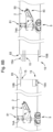
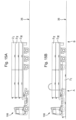
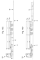
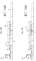
- the transport vehicle 106 can be stationary during these steps, as is shown in fig. 15D the first barrier module 2 I is moved, substantially in its longitudinal direction D, to a second position B next to the first position A, in fig. 15 to the right hand side of the drawing. Then a second module 2 II is lifted from the vehicle 106, into the first position A next to the first module 2 I , as shown in fig. 15E . The second module 2 II is again supported by its drives 5.
- the two coupled first and second modules 2 I , 2 II are again moved in substantially longitudinal direction D, in fig. 15 to the right of the drawing, such that the second module 2 II is moved off the first position A to the second position B, as shown in fig. 15H .
- the first position A is made available for positioning of the third module 2 III on the first position A, which can then be coupled to the free end 83 of the second module 2 II as described before.
- the barrier 1 can be curved around the workers and equipment 125, 126, 128, 128' such that they are protected from traffic moving alongside the barrier 1. Such movement has also been described here before with respect to fig 4 and 16 . Since the drive units 5 can individually be set for a driving direction, the barrier 1 can move in the said longitudinal direction maintaining the bent or curved configuration, or can adapt the configuration based on for example changing road surface, traffic conditions, equipment and/or workers active on and/or above said road surface or the like.
- the remaining series of the coupled barrier modules 2 is then moved along said surface, such that the second barrier module 2 II is moved at least substantially to said first position A, similar to fig. 15G .
- the second barrier module is positioned substantially at said first position A, it is decoupled from a third barrier element 2 III of said series, and is removed from the first position A, lifted onto the vehicle 106, similar to fig. 15E .
- the remaining series of the coupled barrier modules 2 is then moved along said surface, such that the third barrier module 2 III is moved at least substantially to said first position A to be lifted onto the vehicle 106.
- barriers 1 can also be used for protecting vehicles, equipment, buildings and the like structures or such artefacts from such errant vehicles. This has to be understood as being included by protecting workers.
- a barrier 1 or barrier module 2 can be used in combination with a fixed barrier or a stationary, temporary barrier, for example for forming part of a barrier assembly, which part can move in order to divert or reroute traffic from one traffic lane to another traffic lane.
- a barrier of the disclosure can also be used for shielding for example a part of a road, such as a traffic lane, or an area from view, for example in case of a road accident, especially when panels 35 are provided, which may be solar panels or other panels, preferably non-transparent panels.
- a drive 5 for a barrier module 2 or barrier 1 can be a separate drive unit or module 5, which module 5 can but need not include a lift module 43.
- Such module can be mounted to a barrier module 2, such as for example a known concrete or metal barrier body as for example known from NL1006481 .
- the module can be provided such that it can be integrated into the barrier module 2 or such that it can be an add on module, which can for example be temporarily attached to a barrier module 2.
- drives 5 can be used in which the lift 19 or lift module 43 with the support 40 can be combined with the drive 5, especially with the carrier 53 with the sets of wheels 7, integrated into a drive unit. This enables easy movement of the barrier modules or barrier, for example over uneven surfaces.
- the drive units 5 will allow changes in height position of individual drives 5 even during movement of the barrier modules or barrier.
Landscapes
- Engineering & Computer Science (AREA)
- Architecture (AREA)
- Civil Engineering (AREA)
- Structural Engineering (AREA)
- Refuge Islands, Traffic Blockers, Or Guard Fence (AREA)
- Road Signs Or Road Markings (AREA)
Applications Claiming Priority (5)
| Application Number | Priority Date | Filing Date | Title |
|---|---|---|---|
| NL2026832A NL2026832B1 (en) | 2020-11-05 | 2020-11-05 | Traffic barrier, method for using a barrier, and barrier module |
| NL2026833A NL2026833B1 (en) | 2020-11-05 | 2020-11-05 | Traffic barrier, method for using a barrier, and barrier module |
| NL2026834A NL2026834B1 (en) | 2020-11-05 | 2020-11-05 | Traffic barrier, method for using a barrier, and barrier module |
| NL2026837A NL2026837B1 (en) | 2020-11-05 | 2020-11-05 | Traffic barrier, method for using a barrier, and barrier module |
| PCT/NL2021/050683 WO2022098240A1 (en) | 2020-11-05 | 2021-11-05 | Traffic barrier, method for using a barrier, and barrier module |
Publications (3)
| Publication Number | Publication Date |
|---|---|
| EP4240909A1 EP4240909A1 (en) | 2023-09-13 |
| EP4240909B1 true EP4240909B1 (en) | 2025-04-09 |
| EP4240909C0 EP4240909C0 (en) | 2025-04-09 |
Family
ID=78528988
Family Applications (2)
| Application Number | Title | Priority Date | Filing Date |
|---|---|---|---|
| EP21802842.1A Active EP4240909B1 (en) | 2020-11-05 | 2021-11-05 | Traffic barrier, method for using a barrier, and barrier module |
| EP21805672.9A Pending EP4240910A1 (en) | 2020-11-05 | 2021-11-05 | Traffic barrier, method for using a barrier, and barrier module |
Family Applications After (1)
| Application Number | Title | Priority Date | Filing Date |
|---|---|---|---|
| EP21805672.9A Pending EP4240910A1 (en) | 2020-11-05 | 2021-11-05 | Traffic barrier, method for using a barrier, and barrier module |
Country Status (6)
| Country | Link |
|---|---|
| EP (2) | EP4240909B1 (pl) |
| ES (1) | ES3029562T3 (pl) |
| HU (1) | HUE071514T2 (pl) |
| NL (1) | NL2029656B1 (pl) |
| PL (1) | PL4240909T3 (pl) |
| WO (2) | WO2022098240A1 (pl) |
Families Citing this family (2)
| Publication number | Priority date | Publication date | Assignee | Title |
|---|---|---|---|---|
| WO2025131237A1 (de) * | 2023-12-18 | 2025-06-26 | Wenger Projekte Und Coaching | Leitplankenabschnitt mit einem beweglichen fahrwerk, leitplankensystem, strassenweiche sowie verfahren zum versetzen eines leitplankenabschnitts |
| WO2025160625A1 (en) * | 2024-01-30 | 2025-08-07 | CE ITS Holdings Pty Ltd | Moveable median |
Family Cites Families (6)
| Publication number | Priority date | Publication date | Assignee | Title |
|---|---|---|---|---|
| DE8915625U1 (de) * | 1989-11-09 | 1990-11-22 | SPIG Schutzplanken-Produktions-Gesellschaft mbH & Co KG, 6612 Schmelz | Fahrwegseitenbegrenzung |
| NL192928C (nl) | 1990-07-04 | 1998-05-07 | Jansen Venneboer B V | Verplaatsbare inrichting voor het begrenzen van rijbanen. |
| DE4219572C2 (de) * | 1992-06-15 | 1997-07-03 | Sps Schutzplanken Gmbh | Fahrwerk für eine Gleitschwelleneinrichtung |
| NL1006481C2 (nl) | 1997-07-04 | 1999-01-05 | Laura Metaal Eygelshoven B V | Barrierkoppeling. |
| AU2014265099B2 (en) * | 2008-06-13 | 2015-11-26 | Concaten Inc. | Mobile barrier |
| WO2017118475A1 (de) | 2016-01-05 | 2017-07-13 | Wenger, Projekte Und Coaching | Verfahrbarer leitplankenabschnitt |
-
2021
- 2021-11-05 WO PCT/NL2021/050683 patent/WO2022098240A1/en not_active Ceased
- 2021-11-05 ES ES21802842T patent/ES3029562T3/es active Active
- 2021-11-05 WO PCT/NL2021/050682 patent/WO2022098239A1/en not_active Ceased
- 2021-11-05 EP EP21802842.1A patent/EP4240909B1/en active Active
- 2021-11-05 HU HUE21802842A patent/HUE071514T2/hu unknown
- 2021-11-05 EP EP21805672.9A patent/EP4240910A1/en active Pending
- 2021-11-05 NL NL2029656A patent/NL2029656B1/en active
- 2021-11-05 PL PL21802842.1T patent/PL4240909T3/pl unknown
Also Published As
| Publication number | Publication date |
|---|---|
| NL2029656A (en) | 2022-06-21 |
| WO2022098239A1 (en) | 2022-05-12 |
| WO2022098240A1 (en) | 2022-05-12 |
| EP4240909A1 (en) | 2023-09-13 |
| NL2029656B1 (en) | 2022-09-16 |
| EP4240909C0 (en) | 2025-04-09 |
| ES3029562T3 (en) | 2025-06-24 |
| EP4240910A1 (en) | 2023-09-13 |
| PL4240909T3 (pl) | 2025-08-04 |
| HUE071514T2 (hu) | 2025-09-28 |
Similar Documents
| Publication | Publication Date | Title |
|---|---|---|
| US11384494B2 (en) | Safety trailer | |
| EP4240909B1 (en) | Traffic barrier, method for using a barrier, and barrier module | |
| KR101040381B1 (ko) | 중앙분리대를 이용한 제설재 살포가 가능한 제설장치 | |
| JP2023015172A (ja) | 格納式充電ステーション | |
| US20150225913A1 (en) | Mobile barrier | |
| AU2022397722A1 (en) | Anchor protection vehicle | |
| JP7323963B2 (ja) | 自律車両のための車道インフラストラクチャ | |
| KR20140057756A (ko) | 건설토목용 중량구조물 이송용 자주식 전동리프트 | |
| EP3538394A1 (en) | Electricity collector device | |
| CA2765940A1 (en) | Parking garage elevator system for vehicles | |
| KR102381321B1 (ko) | 도로교통 표시장치 | |
| NL2026833B1 (en) | Traffic barrier, method for using a barrier, and barrier module | |
| NL2026834B1 (en) | Traffic barrier, method for using a barrier, and barrier module | |
| KR20140052554A (ko) | 건설토목용 중량구조물 이송용 자주식 전동리프트 | |
| NL2026837B1 (en) | Traffic barrier, method for using a barrier, and barrier module | |
| NL2026832B1 (en) | Traffic barrier, method for using a barrier, and barrier module | |
| ES2831316T3 (es) | Vehículo ferroviario | |
| KR102714727B1 (ko) | 자율주행 청소차의 주행 제어 시스템 | |
| CN113296510B (zh) | 道路作业安全布控自动收放及自跟随系统及其控制方法 | |
| WO2004036528A1 (en) | Pole for carrying a traffic device | |
| ITSP990003A1 (it) | Posteggi automatizzati modulari di grande capienza realizzata a mezzodi carrelli autonomi a gestione elettronica per stoccaggio e prelievo | |
| RU198973U1 (ru) | Укладчик лёгких дорожных матов с адаптивным регулированием положения верхней поворотной рамы | |
| GB2586652A (en) | Electric vehicle charging system and methods | |
| CN208830120U (zh) | 一种自动预标线小车 | |
| CN112356809A (zh) | 一种泊车装置及方法 |
Legal Events
| Date | Code | Title | Description |
|---|---|---|---|
| STAA | Information on the status of an ep patent application or granted ep patent |
Free format text: STATUS: UNKNOWN |
|
| STAA | Information on the status of an ep patent application or granted ep patent |
Free format text: STATUS: THE INTERNATIONAL PUBLICATION HAS BEEN MADE |
|
| PUAI | Public reference made under article 153(3) epc to a published international application that has entered the european phase |
Free format text: ORIGINAL CODE: 0009012 |
|
| STAA | Information on the status of an ep patent application or granted ep patent |
Free format text: STATUS: REQUEST FOR EXAMINATION WAS MADE |
|
| 17P | Request for examination filed |
Effective date: 20230605 |
|
| AK | Designated contracting states |
Kind code of ref document: A1 Designated state(s): AL AT BE BG CH CY CZ DE DK EE ES FI FR GB GR HR HU IE IS IT LI LT LU LV MC MK MT NL NO PL PT RO RS SE SI SK SM TR |
|
| DAV | Request for validation of the european patent (deleted) | ||
| DAX | Request for extension of the european patent (deleted) | ||
| GRAP | Despatch of communication of intention to grant a patent |
Free format text: ORIGINAL CODE: EPIDOSNIGR1 |
|
| STAA | Information on the status of an ep patent application or granted ep patent |
Free format text: STATUS: GRANT OF PATENT IS INTENDED |
|
| INTG | Intention to grant announced |
Effective date: 20241030 |
|
| GRAS | Grant fee paid |
Free format text: ORIGINAL CODE: EPIDOSNIGR3 |
|
| GRAA | (expected) grant |
Free format text: ORIGINAL CODE: 0009210 |
|
| STAA | Information on the status of an ep patent application or granted ep patent |
Free format text: STATUS: THE PATENT HAS BEEN GRANTED |
|
| AK | Designated contracting states |
Kind code of ref document: B1 Designated state(s): AL AT BE BG CH CY CZ DE DK EE ES FI FR GB GR HR HU IE IS IT LI LT LU LV MC MK MT NL NO PL PT RO RS SE SI SK SM TR |
|
| REG | Reference to a national code |
Ref country code: GB Ref legal event code: FG4D |
|
| REG | Reference to a national code |
Ref country code: CH Ref legal event code: EP |
|
| REG | Reference to a national code |
Ref country code: DE Ref legal event code: R096 Ref document number: 602021029001 Country of ref document: DE |
|
| REG | Reference to a national code |
Ref country code: IE Ref legal event code: FG4D |
|
| U01 | Request for unitary effect filed |
Effective date: 20250506 |
|
| U07 | Unitary effect registered |
Designated state(s): AT BE BG DE DK EE FI FR IT LT LU LV MT NL PT RO SE SI Effective date: 20250512 |
|
| REG | Reference to a national code |
Ref country code: ES Ref legal event code: FG2A Ref document number: 3029562 Country of ref document: ES Kind code of ref document: T3 Effective date: 20250624 |
|
| REG | Reference to a national code |
Ref country code: HU Ref legal event code: AG4A Ref document number: E071514 Country of ref document: HU |
|
| PG25 | Lapsed in a contracting state [announced via postgrant information from national office to epo] |
Ref country code: NO Free format text: LAPSE BECAUSE OF FAILURE TO SUBMIT A TRANSLATION OF THE DESCRIPTION OR TO PAY THE FEE WITHIN THE PRESCRIBED TIME-LIMIT Effective date: 20250709 Ref country code: GR Free format text: LAPSE BECAUSE OF FAILURE TO SUBMIT A TRANSLATION OF THE DESCRIPTION OR TO PAY THE FEE WITHIN THE PRESCRIBED TIME-LIMIT Effective date: 20250710 |
|
| PG25 | Lapsed in a contracting state [announced via postgrant information from national office to epo] |
Ref country code: HR Free format text: LAPSE BECAUSE OF FAILURE TO SUBMIT A TRANSLATION OF THE DESCRIPTION OR TO PAY THE FEE WITHIN THE PRESCRIBED TIME-LIMIT Effective date: 20250409 |
|
| PG25 | Lapsed in a contracting state [announced via postgrant information from national office to epo] |
Ref country code: RS Free format text: LAPSE BECAUSE OF FAILURE TO SUBMIT A TRANSLATION OF THE DESCRIPTION OR TO PAY THE FEE WITHIN THE PRESCRIBED TIME-LIMIT Effective date: 20250709 |
|
| PG25 | Lapsed in a contracting state [announced via postgrant information from national office to epo] |
Ref country code: IS Free format text: LAPSE BECAUSE OF FAILURE TO SUBMIT A TRANSLATION OF THE DESCRIPTION OR TO PAY THE FEE WITHIN THE PRESCRIBED TIME-LIMIT Effective date: 20250809 |
|
| REG | Reference to a national code |
Ref country code: CH Ref legal event code: U11 Free format text: ST27 STATUS EVENT CODE: U-0-0-U10-U11 (AS PROVIDED BY THE NATIONAL OFFICE) Effective date: 20251201 |
|
| PGFP | Annual fee paid to national office [announced via postgrant information from national office to epo] |
Ref country code: HU Payment date: 20251121 Year of fee payment: 5 |
|
| U20 | Renewal fee for the european patent with unitary effect paid |
Year of fee payment: 5 Effective date: 20251127 |
|
| PGFP | Annual fee paid to national office [announced via postgrant information from national office to epo] |
Ref country code: GB Payment date: 20251121 Year of fee payment: 5 |
|
| PG25 | Lapsed in a contracting state [announced via postgrant information from national office to epo] |
Ref country code: SM Free format text: LAPSE BECAUSE OF FAILURE TO SUBMIT A TRANSLATION OF THE DESCRIPTION OR TO PAY THE FEE WITHIN THE PRESCRIBED TIME-LIMIT Effective date: 20250409 |
|
| PGFP | Annual fee paid to national office [announced via postgrant information from national office to epo] |
Ref country code: CH Payment date: 20251201 Year of fee payment: 5 |
|
| PG25 | Lapsed in a contracting state [announced via postgrant information from national office to epo] |
Ref country code: CZ Free format text: LAPSE BECAUSE OF FAILURE TO SUBMIT A TRANSLATION OF THE DESCRIPTION OR TO PAY THE FEE WITHIN THE PRESCRIBED TIME-LIMIT Effective date: 20250409 |
|
| PGFP | Annual fee paid to national office [announced via postgrant information from national office to epo] |
Ref country code: PL Payment date: 20251022 Year of fee payment: 5 |
|
| PG25 | Lapsed in a contracting state [announced via postgrant information from national office to epo] |
Ref country code: SK Free format text: LAPSE BECAUSE OF FAILURE TO SUBMIT A TRANSLATION OF THE DESCRIPTION OR TO PAY THE FEE WITHIN THE PRESCRIBED TIME-LIMIT Effective date: 20250409 |
|
| PGFP | Annual fee paid to national office [announced via postgrant information from national office to epo] |
Ref country code: ES Payment date: 20251229 Year of fee payment: 5 |
|
| PLBE | No opposition filed within time limit |
Free format text: ORIGINAL CODE: 0009261 |
|
| STAA | Information on the status of an ep patent application or granted ep patent |
Free format text: STATUS: NO OPPOSITION FILED WITHIN TIME LIMIT |
|
| REG | Reference to a national code |
Ref country code: CH Ref legal event code: L10 Free format text: ST27 STATUS EVENT CODE: U-0-0-L10-L00 (AS PROVIDED BY THE NATIONAL OFFICE) Effective date: 20260218 |
|
| 26N | No opposition filed |
Effective date: 20260112 |