EP4242801A2 - Clavier sans clé avec détection de force et rétroaction haptique - Google Patents
Clavier sans clé avec détection de force et rétroaction haptique Download PDFInfo
- Publication number
- EP4242801A2 EP4242801A2 EP23178477.8A EP23178477A EP4242801A2 EP 4242801 A2 EP4242801 A2 EP 4242801A2 EP 23178477 A EP23178477 A EP 23178477A EP 4242801 A2 EP4242801 A2 EP 4242801A2
- Authority
- EP
- European Patent Office
- Prior art keywords
- input
- force
- region
- top member
- keyboard
- Prior art date
- Legal status (The legal status is an assumption and is not a legal conclusion. Google has not performed a legal analysis and makes no representation as to the accuracy of the status listed.)
- Pending
Links
Images








Classifications
-
- G—PHYSICS
- G06—COMPUTING OR CALCULATING; COUNTING
- G06F—ELECTRIC DIGITAL DATA PROCESSING
- G06F3/00—Input arrangements for transferring data to be processed into a form capable of being handled by the computer; Output arrangements for transferring data from processing unit to output unit, e.g. interface arrangements
- G06F3/01—Input arrangements or combined input and output arrangements for interaction between user and computer
- G06F3/048—Interaction techniques based on graphical user interfaces [GUI]
- G06F3/0487—Interaction techniques based on graphical user interfaces [GUI] using specific features provided by the input device, e.g. functions controlled by the rotation of a mouse with dual sensing arrangements, or of the nature of the input device, e.g. tap gestures based on pressure sensed by a digitiser
- G06F3/0488—Interaction techniques based on graphical user interfaces [GUI] using specific features provided by the input device, e.g. functions controlled by the rotation of a mouse with dual sensing arrangements, or of the nature of the input device, e.g. tap gestures based on pressure sensed by a digitiser using a touch-screen or digitiser, e.g. input of commands through traced gestures
- G06F3/04886—Interaction techniques based on graphical user interfaces [GUI] using specific features provided by the input device, e.g. functions controlled by the rotation of a mouse with dual sensing arrangements, or of the nature of the input device, e.g. tap gestures based on pressure sensed by a digitiser using a touch-screen or digitiser, e.g. input of commands through traced gestures by partitioning the display area of the touch-screen or the surface of the digitising tablet into independently controllable areas, e.g. virtual keyboards or menus
-
- G—PHYSICS
- G06—COMPUTING OR CALCULATING; COUNTING
- G06F—ELECTRIC DIGITAL DATA PROCESSING
- G06F3/00—Input arrangements for transferring data to be processed into a form capable of being handled by the computer; Output arrangements for transferring data from processing unit to output unit, e.g. interface arrangements
- G06F3/01—Input arrangements or combined input and output arrangements for interaction between user and computer
- G06F3/03—Arrangements for converting the position or the displacement of a member into a coded form
- G06F3/041—Digitisers, e.g. for touch screens or touch pads, characterised by the transducing means
- G06F3/044—Digitisers, e.g. for touch screens or touch pads, characterised by the transducing means by capacitive means
- G06F3/0447—Position sensing using the local deformation of sensor cells
-
- G—PHYSICS
- G06—COMPUTING OR CALCULATING; COUNTING
- G06F—ELECTRIC DIGITAL DATA PROCESSING
- G06F3/00—Input arrangements for transferring data to be processed into a form capable of being handled by the computer; Output arrangements for transferring data from processing unit to output unit, e.g. interface arrangements
- G06F3/01—Input arrangements or combined input and output arrangements for interaction between user and computer
- G06F3/03—Arrangements for converting the position or the displacement of a member into a coded form
- G06F3/041—Digitisers, e.g. for touch screens or touch pads, characterised by the transducing means
-
- G—PHYSICS
- G06—COMPUTING OR CALCULATING; COUNTING
- G06F—ELECTRIC DIGITAL DATA PROCESSING
- G06F3/00—Input arrangements for transferring data to be processed into a form capable of being handled by the computer; Output arrangements for transferring data from processing unit to output unit, e.g. interface arrangements
- G06F3/01—Input arrangements or combined input and output arrangements for interaction between user and computer
- G06F3/016—Input arrangements with force or tactile feedback as computer generated output to the user
-
- G—PHYSICS
- G06—COMPUTING OR CALCULATING; COUNTING
- G06F—ELECTRIC DIGITAL DATA PROCESSING
- G06F3/00—Input arrangements for transferring data to be processed into a form capable of being handled by the computer; Output arrangements for transferring data from processing unit to output unit, e.g. interface arrangements
- G06F3/01—Input arrangements or combined input and output arrangements for interaction between user and computer
- G06F3/02—Input arrangements using manually operated switches, e.g. using keyboards or dials
- G06F3/0202—Constructional details or processes of manufacture of the input device
- G06F3/0216—Arrangements for ergonomically adjusting the disposition of keys of a keyboard
-
- G—PHYSICS
- G06—COMPUTING OR CALCULATING; COUNTING
- G06F—ELECTRIC DIGITAL DATA PROCESSING
- G06F3/00—Input arrangements for transferring data to be processed into a form capable of being handled by the computer; Output arrangements for transferring data from processing unit to output unit, e.g. interface arrangements
- G06F3/01—Input arrangements or combined input and output arrangements for interaction between user and computer
- G06F3/02—Input arrangements using manually operated switches, e.g. using keyboards or dials
- G06F3/023—Arrangements for converting discrete items of information into a coded form, e.g. arrangements for interpreting keyboard generated codes as alphanumeric codes, operand codes or instruction codes
- G06F3/0231—Cordless keyboards
-
- G—PHYSICS
- G06—COMPUTING OR CALCULATING; COUNTING
- G06F—ELECTRIC DIGITAL DATA PROCESSING
- G06F3/00—Input arrangements for transferring data to be processed into a form capable of being handled by the computer; Output arrangements for transferring data from processing unit to output unit, e.g. interface arrangements
- G06F3/01—Input arrangements or combined input and output arrangements for interaction between user and computer
- G06F3/03—Arrangements for converting the position or the displacement of a member into a coded form
- G06F3/041—Digitisers, e.g. for touch screens or touch pads, characterised by the transducing means
- G06F3/044—Digitisers, e.g. for touch screens or touch pads, characterised by the transducing means by capacitive means
- G06F3/0445—Digitisers, e.g. for touch screens or touch pads, characterised by the transducing means by capacitive means using two or more layers of sensing electrodes, e.g. using two layers of electrodes separated by a dielectric layer
-
- G—PHYSICS
- G06—COMPUTING OR CALCULATING; COUNTING
- G06F—ELECTRIC DIGITAL DATA PROCESSING
- G06F3/00—Input arrangements for transferring data to be processed into a form capable of being handled by the computer; Output arrangements for transferring data from processing unit to output unit, e.g. interface arrangements
- G06F3/01—Input arrangements or combined input and output arrangements for interaction between user and computer
- G06F3/048—Interaction techniques based on graphical user interfaces [GUI]
- G06F3/0487—Interaction techniques based on graphical user interfaces [GUI] using specific features provided by the input device, e.g. functions controlled by the rotation of a mouse with dual sensing arrangements, or of the nature of the input device, e.g. tap gestures based on pressure sensed by a digitiser
- G06F3/0488—Interaction techniques based on graphical user interfaces [GUI] using specific features provided by the input device, e.g. functions controlled by the rotation of a mouse with dual sensing arrangements, or of the nature of the input device, e.g. tap gestures based on pressure sensed by a digitiser using a touch-screen or digitiser, e.g. input of commands through traced gestures
- G06F3/04883—Interaction techniques based on graphical user interfaces [GUI] using specific features provided by the input device, e.g. functions controlled by the rotation of a mouse with dual sensing arrangements, or of the nature of the input device, e.g. tap gestures based on pressure sensed by a digitiser using a touch-screen or digitiser, e.g. input of commands through traced gestures for inputting data by handwriting, e.g. gesture or text
-
- G—PHYSICS
- G06—COMPUTING OR CALCULATING; COUNTING
- G06F—ELECTRIC DIGITAL DATA PROCESSING
- G06F3/00—Input arrangements for transferring data to be processed into a form capable of being handled by the computer; Output arrangements for transferring data from processing unit to output unit, e.g. interface arrangements
- G06F3/01—Input arrangements or combined input and output arrangements for interaction between user and computer
- G06F3/048—Interaction techniques based on graphical user interfaces [GUI]
- G06F3/0487—Interaction techniques based on graphical user interfaces [GUI] using specific features provided by the input device, e.g. functions controlled by the rotation of a mouse with dual sensing arrangements, or of the nature of the input device, e.g. tap gestures based on pressure sensed by a digitiser
- G06F3/0489—Interaction techniques based on graphical user interfaces [GUI] using specific features provided by the input device, e.g. functions controlled by the rotation of a mouse with dual sensing arrangements, or of the nature of the input device, e.g. tap gestures based on pressure sensed by a digitiser using dedicated keyboard keys or combinations thereof
- G06F3/04892—Arrangements for controlling cursor position based on codes indicative of cursor displacements from one discrete location to another, e.g. using cursor control keys associated to different directions or using the tab key
-
- G—PHYSICS
- G06—COMPUTING OR CALCULATING; COUNTING
- G06F—ELECTRIC DIGITAL DATA PROCESSING
- G06F2203/00—Indexing scheme relating to G06F3/00 - G06F3/048
- G06F2203/041—Indexing scheme relating to G06F3/041 - G06F3/045
- G06F2203/04104—Multi-touch detection in digitiser, i.e. details about the simultaneous detection of a plurality of touching locations, e.g. multiple fingers or pen and finger
-
- G—PHYSICS
- G06—COMPUTING OR CALCULATING; COUNTING
- G06F—ELECTRIC DIGITAL DATA PROCESSING
- G06F2203/00—Indexing scheme relating to G06F3/00 - G06F3/048
- G06F2203/041—Indexing scheme relating to G06F3/041 - G06F3/045
- G06F2203/04105—Pressure sensors for measuring the pressure or force exerted on the touch surface without providing the touch position
-
- G—PHYSICS
- G06—COMPUTING OR CALCULATING; COUNTING
- G06F—ELECTRIC DIGITAL DATA PROCESSING
- G06F2203/00—Indexing scheme relating to G06F3/00 - G06F3/048
- G06F2203/048—Indexing scheme relating to G06F3/048
- G06F2203/04803—Split screen, i.e. subdividing the display area or the window area into separate subareas
Definitions
- the described embodiments relate generally to computing input devices. More particularly, the present embodiments relate to force- and/or touch-sensitive input devices having haptic feedback.
- touch-input devices appear to offer some greater flexibility for input scenarios and customization than mechanical keyboards, mice, and similar input devices.
- touch sensitive input devices often have a flat, inflexible input surface that gives little or no tactile feedback to a user and may therefore be less desirable for many scenarios than traditional input devices.
- An input device for an electronic device may include an enclosure and a top member coupled to the enclosure and defining an input surface having multiple differentiated input regions.
- the input device may further include a first force sensing system associated with a first area of the top member including a first group of the differentiated input regions, the first force sensing system configured to determine a first force associated with a first force input applied within the first area, and a second force sensing system associated with a second area of the top member including a second group of the differentiated input regions, the second force sensing system configured to determine a second force associated with a second force input applied within the second area.
- the input device may further include a touch sensing system configured to determine which input region from the first group of the differentiated input regions corresponds to the first force input and to determine which input region from the second group of the differentiated input regions corresponds to the second force input.
- the first force sensing system may be configured to determine the first force independently of the second force sensing system.
- the first group of the differentiated input regions may correspond to keys typically selected by a first finger of a user's hand, and the second group of the differentiated input regions may correspond to keys typically selected by a second finger of the user's hand.
- the multiple differentiated input regions may correspond to keys of a keyboard.
- the multiple differentiated input regions may be visually differentiated on the top member.
- the input device may be configured to detect a key press of a particular input region by detecting, within a given group of the differentiated input regions, both a touch location and a force value satisfying a force threshold.
- the input device may further comprise a haptic output system configured to produce a tactile output in response to detecting the key press.
- the haptic output system may include a first actuator having a first actuation axis along a first direction and a second actuator having a second actuation axis along a second direction that is not parallel to the first direction.
- the input device may be configured to alternate between actuating the first actuator and the second actuator in response to detecting successive key presses.
- the first and the second force sensing systems may be part of a group of force sensing systems, and the group of force sensing systems may define two rows of force sensing regions on the top member.
- the first and second groups of the differentiated input regions may be oriented substantially diagonally with respect to a longitudinal axis of the input device.
- a keyboard for an electronic device includes an enclosure and a cover coupled to the enclosure and defining an input surface.
- the keyboard also includes a first actuator within the enclosure and coupled to the cover and a second actuator within the enclosure and coupled to the cover.
- the first actuator is configured to impart, to the cover, a first force along a first axis that is substantially parallel to the input surface
- the second actuator is configured to impart, to the cover, a second force along a second axis that is perpendicular to the first axis and substantially parallel to the input surface.
- the first actuator may be configured to oscillate along the first axis to impart the first force to the cover
- the second actuator may be configured to oscillate along the second axis to impart the second force to the cover.
- the keyboard may further include a force sensing system within the enclosure and configured to detect the successive force inputs on the input regions.
- the keyboard may be incorporated into an electronic device that includes a display coupled to the enclosure, wherein the display is distinct from the keyboard.
- the input surface may include input regions representing character input keys, and the first actuator and the second actuator may be configured to provide haptic feedback to a user to induce a sensation representative of a mechanical key.
- the keyboard may be configured to alternate between actuating the first actuator and the second actuator in response to successive force inputs on the input regions.
- the keyboard may also or instead be configured to actuate the first and second actuator substantially simultaneously (or such that the actuations of the first and second actuators overlap in time).
- a force sensing system for an electronic device may include a cover defining an input surface comprising multiple input regions each corresponding to an input key.
- the cover may be configured to locally deform in response to an input force applied to an input region of the multiple input regions.
- the force sensing system may include a capacitive sense layer below the cover, a compliant material between the cover and the capacitive sense layer and below the input regions, and a processor electrically coupled to the capacitive sense layer.
- the processor may be configured to determine a force value of the input force based on a change in capacitance between the capacitive sense layer and an input member applied to the input region, and determine a location of the input force based on which of a set of electrodes detected the change in capacitance.
- the capacitive sense layer may include a set of electrodes each having an area that is the same or smaller than an area of the input regions.
- the force sensing system may be configured to differentiate between force inputs having centroids about 3.0 cm apart or less.
- the force sensing system may be coupled to a lower portion of an enclosure of a notebook computer and may be configured as a keyboard for the notebook computer.
- the multiple input regions may be visually differentiated to define a keyboard for the notebook computer.
- the notebook computer may include a display coupled to an upper portion of the enclosure.
- the cover may be formed from a glass.
- the glass may have an elastic modulus in a range of about 60 to about 80 GPa.
- the glass may have a thickness in a range of about 0.1 to about 0.5 mm.
- the compliant material may have a thickness in a range of about 0.5 mm to about 2.0 mm.
- the compliant material may be a foam.
- the force sensing system may exclude additional capacitive sense layers between the cover and the compliant material.
- the input surface may include multiple input regions each corresponding to an input key, and the capacitive sense layer may include a set of electrodes each having an area that is the same or smaller than an area of the input regions.
- a method of detecting a key press includes determining a number of fingers in contact with an input surface of an electronic device, and determining a force threshold indicative of a key press based at least in part on the number of fingers in contact with the input surface.
- the method may further include detecting a force input that satisfies the force threshold, and in response to detecting the force input, registering a selection of an input region corresponding to a text character.
- the operation of determining the number of fingers in contact with the input surface may include using a touch sensing system to determine the number of fingers in contact with the input surface.
- the force threshold may be between about 25 and 150 grams higher than a baseline force for the determined number of fingers in contact with the input surface.
- the method may further include detecting a touch input corresponding to a movement across the input surface, and in response to detecting the touch input corresponding to the movement across the input surface, changing a position of a cursor on a display of the electronic device.
- the operation of detecting the force input may include detecting the force input with a force sensing system, and the operation of detecting the touch input comprises detecting the touch input with a touch sensing system.
- cross-hatching or shading in the accompanying figures is generally provided to clarify the boundaries between adjacent elements and also to facilitate legibility of the figures. Accordingly, neither the presence nor the absence of cross-hatching or shading conveys or indicates any preference or requirement for particular materials, material properties, element proportions, element dimensions, commonalities of similarly illustrated elements, or any other characteristic, attribute, or property for any element illustrated in the accompanying figures.
- the following disclosure relates to an input device that uses touch and/or force sensing to detect user inputs, and uses haptic outputs to provide feedback to a user.
- an input device is a keyboard that does not have mechanical or movable keys. Instead, the keyboard may have a flat, keyless input surface, such as a glass or metal layer, and may include touch and/or force sensing systems to determine when a user touches and/or presses on the surface.
- Haptic actuators may provide physical feedback to indicate that a user has pressed the keyless surface with sufficient force to register an input.
- the haptic actuators may induce a physical sensation that is similar to or representative of a mechanical key. For example, when a user presses the surface of the keyboard with sufficient force, the surface may vibrate or otherwise move to indicate to the user that the intended input has been registered.
- Using force sensing in addition to touch sensing may allow a user to use a keyless keyboard more similarly to a mechanical keyboard. For example, when typing, users typically rest multiple fingers on the keyboard. With only touch sensing on a keyless keyboard (e.g., without force sensing), it may be difficult or impossible to determine whether a user is attempting to select a particular key, or whether the user is merely resting a finger on that key. Force sensing, instead of or in addition to touch sensing, allows a keyless keyboard to differentiate between incidental contact and intentional key selections.
- Force sensing in a keyless keyboard may be either global or local.
- the keyboard may determine a total amount or magnitude of force applied to the surface regardless of the position or number of fingers on the surface.
- users may rest their fingers on keys that are not being actively selected.
- different users may rest different numbers of fingers on the keys, or rest them with different amounts of force.
- the same user may rest different numbers of fingers on the keys at different moments while typing.
- the force threshold for detecting a key press may change depending on how many fingers are touching the keyboard.
- a keyboard with global force sensing may set a force threshold that determines whether a key is pressed based on the number of fingers that are in contact with the surface at a given time (as detected by a touch sensing system, for example).
- the keyboard may determine an amount or magnitude of force applied to a particular location or locations on the surface.
- One example local force sensing system uses a pixelated capacitive sense layer below the surface of the keyboard. When pressed, the user's finger may form a depression in the keyboard surface beneath the finger. The pixelated capacitive sense layer may detect the depth and/or location of the depression to determine both an amount and a location of a force. Keyboards may use either global or local force sensing alone, or they may use a combination of these techniques.
- Haptic output may also be global or local.
- the entire keyboard surface may move to provide a haptic output.
- all of the fingers that are resting on the keyboard surface may sense the haptic output.
- Global haptic outputs may be produced, for example, with a haptic actuator that moves the entire surface in-plane with an input surface of the keyboard (e.g., an x- or y-direction) or out-of-plane with the input surface (e.g., a z-direction).
- multiple haptic actuators may be provided in order to provide discrete global haptic outputs for subsequent key presses.
- a single haptic actuator that vibrates the input surface may not be able to produce successive, discrete haptic outputs with a key-strike frequency of a user. Accordingly, multiple haptic actuators may be used. In some cases, the actuators may produce different haptic outputs, such as vibrations in different directions. Users may be able to differentiate between such outputs, even if they are produced substantially simultaneously.
- haptic outputs For local haptic outputs, only a portion of the keyboard may move.
- localized haptic actuators such as piezoelectric elements may cause localized deformations in the surface that are felt only (or primarily) by a finger directly under the deformation.
- electrostatic elements may selectively apply an electrostatic charge to the input surface or to portions thereof. The electrostatic charge may alter or modify a tactile or touch-based stimulus that is perceived by a user. The electrostatic charge may cause an actual or perceived change in friction or surface roughness between an object (e.g., the user's finger) and the input surface by electrostatically attracting the user's finger to the surface.
- a keyboard may use global or local haptic outputs, alone or in combination, to provide a desired haptic output to the user.
- the keyboard may provide numerous other features and functions beyond mere keyboard input.
- the keyboard may include an adaptive display to render visual information, such as an outline of an input region (e.g., representing a key) and an indication of its function (e.g., a glyph). In this way, the location, size, spacing and/or arrangement of the keys may vary.
- the input surface of the keyboard may act as a touch pad to detect touch inputs (e.g., moving a cursor, manipulating user interface elements) as well as typing inputs.
- keyboard as an example input device that uses force sensing to detect inputs and haptic outputs to provide tactile feedback
- these techniques may be used in other input devices as well.
- the input device includes an adaptive display
- the display may present representations of varied affordances or objects that can be manipulated and for which physical feedback can be provided, such as audio mixers, buttons, musical instruments, etc.
- force sensing and haptic outputs may be used in devices other than flat, keyboard-like input devices.
- a rotating input device such as a knob, may detect inputs with force sensing systems and provide haptic outputs to convey feedback to a user.
- FIG. 1 illustrates an example keyboard 100 that uses force sensing systems to detect user inputs and uses haptic actuators to provide tactile outputs.
- the keyboard 100 is in the form of a stand-alone keyboard.
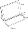
- the keyboard 100 may be coupled to other devices (physically and/or communicatively), such as a desktop computing system ( FIG. 18 ), a laptop or notebook computing system ( FIGS. 16 and 17 ), a cover for a portable electronic device ( FIG. 19 ), a mouse, and so on.
- Example internal components of the keyboard 100 (and/or a computing device to which the keyboard 100 may be physically or communicatively coupled) are described below with respect to FIG. 20 .
- the keyboard 100 includes an enclosure 102 and a top member or cover 104 coupled to the enclosure 102.
- the enclosure 102 may provide structural support to the top member or cover 104, and may include additional features such as a support stand 108.
- the keyboard 100 may include within the enclosure 102 components such as force sensing systems, haptic actuators, touch sensing systems, display components, and the like.
- the cover 104 defines an input surface of the keyboard 100.
- the cover 104 is positioned on a top surface of the keyboard 100, instead of physical keys.
- the cover 104, or top member may be or may include any appropriate materials, such as glass, metal, plastic, etc.
- the cover 104 may include or be coupled to other layers, such as filters, coatings, touch-sensitive layers, liquid crystal layers, display components (e.g., organic light emitting diode (OLED) layers, light sources, light guides), and the like.
- the keyboard 100 may also include one or more mechanical keys.
- the cover 104 may operate as a touch-sensitive surface.
- the cover 104 may respond to a touch input and may include or be coupled to a touch sensing system configured to determine the location of a touch input on the cover 104.
- the cover 104 may receive a wide variety of touch inputs, which may be used to interpret a diverse set of commands or operations.
- the cover 104 may additionally or alternatively be configured to operate as a force-sensitive surface.
- the cover 104 may include or be coupled to a force sensing system configured to detect a location and/or amount of force applied to the cover 104.
- the force sensing system may include (or may be operably connected to) force sensing circuitry configured to determine or estimate an amount of applied force.
- the force sensing circuitry may output a signal or otherwise register that an input has been detected in response to determining an amount of force that exceeds a force threshold.
- the force threshold may be fixed or variable, and more than one threshold may be provided corresponding to different inputs. For example, the threshold may be based on the number of fingers in contact with the cover 104.
- the cover 104 may also include differentiated input regions 106.
- the differentiated input regions 106 may correspond to character input keys (e.g., alphanumeric characters, symbolic characters, text spaces, tabs, and the like).
- other keys may control other aspects of a device without necessarily resulting in a character input (e.g., to control audio volume, screen brightness, or other device functions).
- the differentiated input regions 106 may be regions of a cover (or other top member that defines an input surface) that are visually and/or tactilely differentiated or distinguished from one another with paint, ink, etching, grooves, bumps, ridges, textures, or the like. Differentiated input regions 106 may correspond to character input keys (e.g., keys of an alphanumeric keyboard), buttons, or other affordances. Differentiated input regions 106 may be referred to herein simply as input regions 106.
- the differentiated input regions 106 may be differentiated from one another virtually.
- the cover 104 may include or be part of an adaptable display.
- the adaptable display may be an illuminated display that is configured to display visual indicia that correspond to one or more differentiated input regions 106.
- the differentiated input region 106 is virtually defined by the adaptable display, it may be referred to as a virtual key.
- One or more different sets of visual indicia may be displayed, depending on the type of affordance being emulated, user preference, and/or an application being controlled by the keyboard 100.
- the keyboard 100 may also include various other components or devices depicted or not depicted in FIG. 1 .
- the keyboard 100 may also include one or more ports or electrical connectors positioned along one or more sides of the enclosure 102.
- the ports may include, for example, a USB connection port, an IEEE 1394 data port, audio connection port, video connection port, or other electrical hardware port that is configured to transmit and/or receive signals or data.
- the ports may also include a power connection port that is configured to receive electrical power from an external source such as a wall outlet or other power source.
- the keyboard 100 may also include a wired communication connection 110 for connecting to another device, or the keyboard 100 may include wireless transmitters and/or receivers for communicating with another device.
- Other internal components may be included, such as a processing unit. Several such internal components are described below with respect to FIG. 20 .
- the keyboard 100 may include haptic actuators that are configured to move or otherwise impart a force to the entire cover 104 or top member of the keyboard 100.
- FIG. 2 is a top view of the keyboard 100, illustrating an example that includes a first actuator 202 and a second actuator 206 within the enclosure 102 and coupled to the cover 104.
- the first and second actuators 202, 206 may be coupled anywhere within or to the keyboard 100 as long as they impart a force to the cover 104 or otherwise produce a haptic output detectible on a top member of the keyboard 100.
- the first and second actuators 202, 206 may impart to the cover 104 or other top member forces along different axes or directions.
- the first actuator 202 may impart a force along an actuation axis or direction indicated by the arrow 204
- the second actuator 206 may impart a force along an actuation axis or direction indicated by the arrow 208.
- These directions may be substantially perpendicular to one another, though other relative orientations are also possible (e.g., parallel, 45 degrees, 30 degrees, etc.).
- a single actuator may not be capable of providing haptic outputs (or desirable haptic outputs) at a rate sufficient to keep up with some users' typing speed. For example, some typists may strike keys at a frequency of up to ten characters per second (or more), and a single haptic actuator may not be able to produce outputs at this frequency, especially haptic outputs with relatively longer durations (e.g., outputs that are longer than 100ms). Outputs of such durations may be desirable, however, to more closely mimic the tactile sensation of clicking on a mechanical key, or to otherwise provide a desirable user experience. Accordingly, a second haptic actuator may be provided.
- first and second actuators 202, 206 By positioning the first and second actuators 202, 206 so that they impart perpendicular forces on the cover 104, interference between the motions or vibrations caused by the actuators may be reduced. For example, if the first and second actuators 202, 206 imparted forces along the same axes, the motions or vibrations imparted to the cover 104 by each actuator may cancel each other out, or otherwise interfere with each other. Moreover, it may be difficult or impossible for a user to differentiate haptic outputs from the different actuators, especially when they are both active at the same time (e.g., to indicate simultaneous or overlapping key presses).
- a user may be able to discern when two haptic outputs are provided, even if the outputs overlap. While the outputs may feel the same or similar to one another (e.g., a user may not be able to differentiate the direction of the haptic actuator that produced a particular output), the start and/or end of a haptic output from one actuator may be detectable to a user even when it occurs during a haptic output from the other actuator.
- the first and second actuators 202, 206 may be actuated in an alternating pattern.
- the first and second actuators 202, 206 may be actuated in an alternating pattern only when a typing speed (e.g., a frequency of force inputs) exceeds a certain value, such as a frequency that is above the response frequency of only a single actuator. In such cases, if the typing speed is below the value, only one of the actuators may be used (or they may be used in a pattern other than an alternating pattern).
- a typing speed e.g., a frequency of force inputs
- the first and second actuators 202, 206 may be any appropriate mechanisms or systems for producing haptic outputs or otherwise imparting a force to the cover 104. Suitable actuators may include electromechanical actuators, piezoelectric actuators (e.g., piezoelectric actuators coupled directly to the cover 104, piezo benders below the cover 104 that lift or move the cover 104), linear actuators, voice coil motors, Lorentz force actuators, electro-active polymer actuators, and so on.
- the first and second actuators 202, 206 may be linear actuators each including a coil and a corresponding magnet, where passing a current through a coil moves the corresponding magnet (or otherwise imparts a force on the magnet).
- the first and second actuators 202, 206 may impart forces to the cover 104 to produce varying kinds of haptic outputs.
- the first and second actuators 202, 206 may oscillate along their respective axes (arrows 204, 208 in FIG. 2 ), thus imparting a vibration or oscillation to the cover 104.
- the first and second actuators 202, 206 may impart a single impulse (e.g., a single application of force in a single direction) to the cover 104. In either case, the force may be applied to a move a weight that is coupled to the actuator, or the force may be applied directly to the cover 104.
- FIG. 2 illustrates two actuators
- some embodiments may include more actuators.
- the actuators may be positioned to impart forces or oscillations along different directions (e.g., offset by 45 degrees from one another).
- some of the actuators may impart forces or oscillations along the same directions.
- the first and second actuators 202, 206 may impart forces to the cover 104 (or top member) that are in plane (or substantially in plane) with the input surface defined by the cover 104 or other top member.
- FIGS. 3A-3C depict a simplified cross-sectional view of the input device of FIG. 2 , viewed along line B-B in FIG. 2 .
- the cross-section shown in FIGS. 3A-3C does not include internal features, components, layers, sensors, etc. that may be present in the keyboard 100.
- the position of the second actuator 206 is merely for illustration, and may be positioned in a different location or to a different component than shown in FIGS. 3A-3C .
- the keyboard 100 may include additional layers or components below (and optionally coupled to) the cover 104. In such cases, the second actuator 206 may be below the additional layers or components.
- FIG. 3A shows the keyboard 100 before a finger 300 touches the cover 104.
- the second actuator 206 is at rest.
- FIG. 3B shows the keyboard 100 after an input has been registered by the keyboard 100 or a device coupled to the keyboard (e.g., after the finger 300 has pressed on the cover 104 with a force that satisfies a force threshold).
- the second actuator 206 imparts a force on the cover 104 that causes the cover 104 to move in the direction of arrow 302.
- the second actuator 206 may then reverse the direction of the force, causing the cover 104 to move in the direction of arrow 304 ( FIG. 3C ).
- the motion of the cover 104 may be a wholesale motion of the cover 104 (e.g., the cover moves, even if only microns in either direction), or it can correspond to motion caused by a vibration or oscillation propagating through the cover 104 in the directions of the arrows 302, 304 (which may not result in a translation of the cover 104).
- FIGS. 2 and 3A-3C illustrate actuators that impart forces that are in-plane (e.g., substantially parallel) to a top member of the keyboard 100.
- actuators that impart forces that are in-plane (e.g., substantially parallel) to a top member of the keyboard 100.
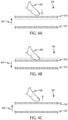
- FIGS. 4A-4C depict an example of the keyboard 100 where an actuator causes the top member to move in a direction that is out-of-plane with the input surface of the top member (e.g., perpendicular to the direction of a force input).
- FIGS. 4A-4C depict a partial cross-sectional area of the keyboard 100, viewed along line B-B in FIG. 2 , illustrating an out-of-plane haptic output that may be produced by an actuator.
- the cover 104 may be moved upward (indicated by the arrow 402) by an actuator.
- the actuator may permit or cause the cover 104 to move downward, as indicated by the arrow 404 in FIG. 4B .
- the actuator may move the input surface upward (indicated by the arrow 406 in FIG. 4C ), which may return the input surface to its original position or move it further upward.
- the cover 104 may be suspended relative to the enclosure 102 by a suspension system (not shown).
- the suspension system may take many forms, and may include springs, foams, compliant members or materials, or other mechanisms that allow the cover 104 to move relative to the enclosure 102 to provide a haptic output.
- a subset of the movements depicted in FIGS. 4A-4C may be implemented.
- an actuator in response to a force input, an actuator may cause the cover 104 to "pop" or deflect upwards as depicted in FIG. 4A and quickly return.
- the actuator may instead cause the cover 104 to deflect downward as depicted in FIG. 4B and quickly return as depicted in FIG. 4C in response to the force input.
- FIGS. 2-4C are examples of actuators that produce global haptic outputs, or haptic outputs that affect or can be felt across the entire surface of the keyboard 100.
- local haptic outputs may be used instead of or in addition to global haptic outputs.
- FIGS. 5A-5C depict a partial cross-sectional area of the keyboard 100, viewed along line B-B in FIG. 2 , illustrating a local haptic output that may be produced by an actuator or a combination of actuators.
- a sensor such as a touch or proximity sensor may detect the presence and/or approach of the finger 500.
- an actuator may cause the input region 502 of the cover 104 to move upward to meet the finger 500.
- an electromechanical or piezoelectric actuator operatively coupled to the cover 104 may be actuated to cause a localized deflection of the input region 502.
- the actuators that locally deform the cover 104 may be any suitable actuator, such as electromechanical actuators, piezoelectric actuators (e.g., piezoelectric actuators coupled directly to the cover 104, piezo benders below the cover 104 that locally deform the cover 104), linear actuators, voice coil motors, Lorentz force actuators, electro-active polymer actuators, and so on.
- electromechanical actuators piezoelectric actuators (e.g., piezoelectric actuators coupled directly to the cover 104, piezo benders below the cover 104 that locally deform the cover 104), linear actuators, voice coil motors, Lorentz force actuators, electro-active polymer actuators, and so on.
- piezoelectric actuators e.g., piezoelectric actuators coupled directly to the cover 104, piezo benders below the cover 104 that locally deform the cover 104
- linear actuators e.g., voice coil motors, Lorentz force actuators, electro-active polymer actuators, and
- the actuator may allow the input region 502 to move downward as depicted in FIG. 5B .
- the actuator may cause the input region 502 to move upward again, whether returning the input region 502 to its original position or moving further upward.
- the movements depicted in FIGS. 5A-5C are implemented individually or together, they may provide to a user the sensation of a click or motion similar to a key or button press.
- multiple such input regions 502 may be defined and separately controllable across the cover 104 to provide localized feedback across the input surface defined by the cover 104 (or other top member).
- an actuator may cause the input region 502 to "pop" or deflect upwards as depicted in FIG. 5A and quickly return.
- the actuator may instead cause the input region 502 to deflect downward as depicted in FIG. 5B and quickly return as depicted in FIG. 5C in response to the force input.
- FIGS. 6A-6C depict simplified cross-sectional views of the input device of FIG. 2 , viewed along line B-B in FIG. 2 , showing an example haptic actuator 601 that may produce localized deformations or deflections of a cover 104.
- the haptic actuator 601 may be configured to retract and/or extend vertically (as oriented in FIGS. 6A-6C ) to impart tactile outputs to the cover 104.
- FIG. 6A shows the haptic actuator 601 in a resting or neutral state
- FIG. 6B shows the haptic actuator 601 in a retracted state, resulting in a localized depression of the cover 104.
- FIG. 6C shows the haptic actuator 601 in an extended state, resulting in a localized protrusion of the cover 104.
- the haptic actuator 601 may be affixed to the cover 104 and a lower support, such as the enclosure 102, so that when the haptic actuator 601 retracts (e.g., is shortened vertically), the haptic actuator 601 pulls down on the cover 104 and locally deforms and/or deflects the cover 104.
- the haptic actuator 601 may be affixed to the cover 104 and the enclosure 102 (or any other suitable component or structure) with an adhesive, such as a pressure or heat sensitive adhesive, epoxy, glue, or the like.
- the haptic actuator 601 may include electrode layers 604 (e.g., 604-1, ..., 604-n) interleaved with compliant layers 602 (e.g., 602-1, ..., 602-n).
- the electrode layers 604 may be selectively electrically charged such that the electrode layers (e.g., adjacent electrode layers) are attracted to one another.
- a first electrode layer 604-1 may be positively charged and a second electrode layer 604-2 may be negatively charged, thus causing the first and second electrode layers 604-1 , 604-2 to be attracted to one another.
- This attraction force may result in a first compliant layer 602-1 being deformed as the first and second electrode layers 604-1, 604-2 are drawn together by the attractive force between the electrodes (e.g., an electrostatic force). Similar charges may be applied to other electrode layers 604 to cause the whole haptic actuator 601 to retract. On the other hand, to extend the haptic actuator 601 to produce an upwards force on the cover 104 (e.g., to form a protrusion), the electrode layers 604 may be electrically charged with a same or similar charge, causing the electrode layers 604 to repel one another. For example, all of the electrode layers 604 may be positively charged. The resulting repulsive force (e.g., electrostatic repulsion) may cause the compliant layers 602 to stretch vertically, thus producing a localized protrusion or deformation in the cover 104.
- electrostatic repulsion e.g., electrostatic repulsion
- the haptic actuator 601 may be configured to produce various types of haptic outputs.
- the haptic actuator 601 may be repeatedly pulsed to produce a vibration, or it may be actuated once to produce a deformation in one direction followed by a return to a neutral state, producing a single "pop" type haptic output.
- These and other types of haptic outputs may include retractions of the haptic actuator 601, extensions of the haptic actuator, or both types of movements.
- a vibration may be produced by cyclically applying a certain charge to the electrode layers 604 so that they are attracted to adjacent electrode layers 604, thus compressing the compliant layers 602 and retracting the actuator 601.
- the electrode layers 604 may produce no forces, thus letting the haptic actuator 601 return to a neutral position.
- a vibration may be produced by cyclically applying a charge to the electrode layers 604 that result in the electrode layers 604 repelling one another, followed by removal of the charges to allow the haptic actuator 601 to return to the neutral position.
- a vibration may also be produced by alternating between attractive and repulsive charges, resulting in an alternating retraction and extension of the actuator 601. Similar modes of operation may be used to produce non-repeating haptic outputs, such as a single "pop" type output described above.
- FIGS. 6A-6C show a single haptic actuator 601
- a keyboard e.g., the keyboard 100
- other input device or device may include multiple haptic actuators 601.
- FIG. 6D shows an example arrangement of haptic actuators 601 relative to the cover 104.
- FIG. 6D shows haptic actuators 601 arranged in a keyboard pattern in which at least one actuator 601 is beneath each input region (which may correspond to keys of a keyboard layout).
- a single actuator 601 may underlie each letter and number key, while some input regions, such as a region 605 that may correspond to a space bar, may include multiple actuators 601.
- mapping actuators 601 to particular input regions as shown in FIG.
- the actuators 601 may be arranged in a grid pattern.
- the keyboard 100 may include a discrete haptic actuator 601 for each of a subset of keys, while other keys share a haptic actuator 601.
- each letter and number key of the keyboard 100 may correspond to a different haptic actuator 601, while other groups of non-letter keys, such as a tab key, caps lock key, left-shift key, and left control key, may share a common haptic actuator 601.
- FIG. 6E shows another example arrangement of haptic actuators 601 relative to the cover 104.
- the haptic actuators 601 may be formed from a single sheet or otherwise interconnected via one or more connecting elements 606.
- the connecting elements 606 may be the same material that formed the compliant layers 602 of the actuators 601 themselves.
- the haptic actuators 601 and the connecting elements 606 may be an integrated structure.
- the haptic actuators 601 and the connecting elements 606 may be formed by cutting continuous sheets of compliant material to form the actuators 601, the connecting elements 606, and gaps 610. Such sheets may then be laminated with the electrodes 604 to form a unitary sheet of actuators 601 and connecting elements 606. While the connecting elements 606 may join the haptic actuators 601 into a single common structure, the connecting elements 606 may omit the electrode layers 604. This configuration can maintain electrical isolation of the actuators 601 to allow independent actuation of the actuators 601.
- the gaps 610 may provide clearance around the haptic actuators 601 to allow lateral deformation of the actuators 601 when the actuators are compressed.
- the gaps 610 are free space (e.g., air), while in other cases another material is introduced into the gaps, such as a material that is more compliant than the compliant layers 602 (and therefore allow lateral deflection of the compliant layers 602).
- the connecting elements 606 may provide several benefits. For example, they may provide additional structural support to the cover 104 by providing less unsupported area between adjacent actuators 601. Further, they may help isolate or localize deflections produced by force inputs and/or key selections, which may improve local force and/or touch sensing functions. For example, it may improve the resolution with which a force sensing system can detect the location of a force input.
- the haptic actuator 601 is used to produce localized haptic outputs.
- the cover 104 is shown locally deflecting or deforming in response to an extension or retraction of the haptic actuator 601.
- Such protrusions and depressions in the cover 104 may be facilitated by a cover 104 that is sufficiently flexible to produce local deformations and/or deflections.
- the cover 104 is glass
- the glass may have an elastic modulus in a range of about 60 to 80 GPa, and a thickness in a range of about 0.1 mm to 0.5 mm.
- Other dimensions, properties, and materials e.g., plastic, fabric, metal are also possible.
- cover 104 may be reinforced or stiffened in certain areas to help isolate deformations and/or deflections produced by the haptic actuator 601.
- ribs may be formed on or applied to the bottom of the cover 104 between various haptic actuators 601.
- the ribs may extend to another structure, such as the enclosure 102, or they may extend only partially to another structure (such as the ribs 1007 shown in FIGS. 10B and 11B ).
- the haptic actuator 601 may be configured to produce global haptic outputs, such as those described with respect to FIGS. 4A-4C .
- the cover 104 may be configured to resist or minimize local deformations or deflections, such that the forces applied by the haptic actuator 601 may be perceived anywhere on the cover 104 (or at least over a greater area than that of the haptic actuator itself).
- the cover 104 may be thicker and/or stiffer than a cover 104 used for localized haptic outputs. More particularly, the cover 104 may be glass having a thickness in a range of about 0.75 to 2.0 mm. Alternatively, the cover 104 may be metal, plastic, or the like.
- a device may include multiple haptic actuators 601, which may be operated simultaneously or individually.
- the haptic actuator 601 may include any suitable number of compliant layers 602 and electrode layers 604.
- the haptic actuator 601 may include 40 compliant layers 602 and 41 electrode layers 604, with each compliant layer 602 sandwiched between two electrode layers 604.
- the electrode layers 604 may be formed of or include any suitable material, such as gold, aluminum, copper, indium tin oxide (ITO), or the like.
- the compliant layers 602 may likewise be formed of or include any suitable material such as silicone, latex, elastomers, polymers, gels, or any other compliant material.
- the compliant layers 602 may be any suitable thickness, such from about 10 microns to about 50 microns thick. In some case they are about 25 microns thick.
- the actuator 601 When viewed from the top, the actuator 601 may have any suitable shape, such as square, rectangular, round, or the like. In some cases, when viewed from the top (e.g., through the cover 104) the actuator 601 has length and width dimensions of about 40 x 40 mm, about 25 x 25 mm, or about 15 x 15 mm. In some cases, the actuator 601 has substantially the same dimensions as an input region (e.g., a virtual key) that it underlies. Other dimensions are also contemplated.
- an input region e.g., a virtual key
- Haptic actuators 601 may be arranged in a keyboard 100 (or other input device) in any suitable manner. For example,
- any of the foregoing haptic outputs may be produced in response to the keyboard 100 detecting a force input that satisfies a threshold (e.g., a force threshold).
- a threshold e.g., a force threshold
- the haptic outputs may be used to indicate to a user that they have pressed the keyboard 100 with enough force to register the input.
- the keyboard 100 may induce a sensation that mimics or suggests the action of a mechanical keyboard, with the haptic output representing the sensation of a collapsing mechanical key.
- properties of the haptic output or outputs used by the keyboard 100 may be selected or optimized to provide a tactile feeling that is similar to that of a collapsing mechanical key.
- the haptic outputs may not be produced in response to inputs corresponding to incidental contact due to fingers resting on the keyboard 100, low-force inputs due to touch inputs to the keyboard 100 (e.g., when the input surface is being used as a trackpad), or the like.
- a keyless keyboard such as the keyboard 100, may include one or more force sensing systems that facilitate detection of user inputs.
- a force sensing system corresponds to any combination of mechanisms and associated processors, software, etc. that can determine an amount of force applied to a surface or to a portion thereof.
- force sensing systems may include one or more force sensing elements, such as piezoelectric elements, strain gauges, optical displacement sensors, or the like.
- a single force sensing system may be used to determine an aggregate amount of force applied to the cover 104 (e.g., global force sensing).
- this type of force sensing system may provide insufficient information to determine a location of the physical contact that is producing the detected force. (Or it may not be able to determine the location to a suitable resolution.)
- a touch sensing system may be used to determine the location of each contact between a user's finger (or other implement or input member) and the cover 104. Accelerometers may also be used in conjunction with the touch sensing system and the force sensing system to determine the location of a force input.
- one or more accelerometers, and associated processors may detect vibration or motion signatures that are indicative of an input from a particular finger or at a particular location on the input surface of the keyboard 100.
- a touch sensing system and a global force sensing system may be used to determine when and where a user is attempting to apply an input on the surface of the keyboard 100.
- multiple force sensing systems may be used to determine an amount of force applied to discrete areas or known locations on the cover 104.
- each input region 106 of the keyboard 100 e.g., corresponding to the size and/or location of a traditional key such as a character input key
- each key is separately monitored to detect force inputs.
- the keyboard 100 is divided into multiple force sensing regions or pixels, at least some of which include multiple keys. In particular, based on typical typing patterns, there may be groups of keys that are unlikely to be contacted simultaneously.
- a user may rest his or her fingers along a "home row” or a central row of keys, and move his or her fingers away from the home row to strike individual keys. Because of the horizontal positioning of a user's fingers relative to the keyboard, it is less likely that a user will be touching multiple keys in a single column at any given time. As a more specific example, on a traditional "QWERTY" keyboard, a user's fingers may be resting on the "a” key while striking the "f" key, but it is less likely that the user's fingers will be resting on the "a” key while striking the "q” key. Accordingly, it may be possible to increase the precision of a force-sensitive keyboard by providing force sensing pixels (as opposed to a global force sensing system, for example) without resorting to a different force sensing system or force sensing element for each key.
- Such force sensing pixels may encompass different groups of input regions and may detect forces substantially independently of one another. For example, a force input applied to one force sensing pixel may be detected by a force sensing system (or element) associated with that force sensing pixel, but may not be detected by a force sensing system (or element) associated with a different force sensing pixel (or it may not satisfy a detection threshold of the second force sensing system or element). In some cases, each force sensing pixel (and/or a force sensing element associated with each force sensing pixel) produces a force value distinct from each other force value.
- a processor may use a first force sensing system or element associated with a first force sensing pixel (independently of a second force sensing system or element that is associated with a different force sensing pixel) to determine the force applied to the first force sensing pixel.
- the processor may use the second force sensing system or element associated with the second force sensing pixel (independently of the first force sensing system or element) to determine the force applied to the second force sensing pixel. Accordingly, each force sensing pixel can be independently evaluated to determine whether a force input has been applied to that particular force sensing pixel and/or the amount of force applied to the particular pixel.
- FIGS. 7A-7B depict the keyboard 100 with different example force sensing regions or force pixel arrangements.
- force sensing regions 702 (or pixels) are arranged in substantially two rows, with a first row above line 701 and a second row below line 701.
- the line 701 divides the keyboard roughly in half lengthwise, and there are ten force sensing regions 702 in each row.
- force sensing regions 704 are also arranged in substantially two rows, with a first row above line 703 and a second row below line 703.
- FIG. 7B includes eight force sensing regions 704 in each row.
- the force sensing regions 704 may be oriented substantially diagonally (with respect to a longitudinal axis of the keyboard extending from left to right in FIG. 7B ). This arrangement may correspond to a typical typing pattern, where each particular finger tends to be used to press keys in diagonal groupings.
- each row includes at least eight force sensing regions.
- each row includes at least a separate force sensing region for each area that is accessible by (or typically struck by) a particular finger (excluding thumbs in the case of the eight pixel arrangement).
- at least a subset of the force sensing regions 702, 704 encompass groups of at least two separate input regions/keys (e.g., the force sensing regions are configured to detect a force applied to at least two separate input regions/keys).
- force sensing regions in FIGS. 7A-7B are merely examples.
- force sensing regions may encompass different input regions (e.g., keys) than those shown in these figures.
- the force sensing regions 702 ( FIG. 7A ) and 704 ( FIG. 7B ) may each correspond to one force sensing system or element. That is, a force applied to anywhere in the force sensing regions 702, 704 may result in a single force value without regard to the location of the force.
- the force sensing system or element may use any suitable force sensing technology and/or technique, including capacitive force sensing, piezoelectric force sensing, strain gauges, or the like.
- the force sensing system or element for each force sensing region 702, 704 may be located below the force sensing region and within the enclosure 102 of the keyboard 100.
- the cover 104 may be segmented along the borders of the force sensing regions 702, 704 to allow each force sensing region to move at least somewhat independently of one another.
- the cover 104 is grooved along the borders of the force sensing regions 702, 704 (e.g., on the bottom surface or the top surface). The grooves may allow the force sensing regions 702, 704 to move substantially independently of one another and may reduce the extent to which one force sensing region deflects in response to a force applied to an input region in a neighboring force sensing region. This may improve the independence of the force detected at each force sensing region.
- each force sensing region may be configured to detect key presses in response to different force values. For example, force inputs detected in the force sensing regions may be compared against different force thresholds.
- force sensing regions that are typically subjected to lower forces such as those typically struck by a user's pinky finger, may use a different (e.g., lower) force threshold than those regions typically struck with greater force, such as those typically struck by a user's index finger or thumb.
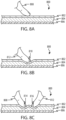
- FIGS. 8A-8C show partial cross-sectional views of the keyboard 100 (e.g., viewed along line A-A in FIG. 1 ), illustrating an example localized force sensing system 800 that may be used in conjunction with the embodiments described herein.
- the force sensing system 800 may provide localized force sensing such that both the force and location of individual force inputs from a finger, stylus, or other implement or input member may be determined.
- the resolution of the force sensing system 800 may be substantially equal to or greater than the resolution of the input regions, such that each force input can be reliably associated with a given input region.
- the force sensing system 800 may include a cover 802 (corresponding to the cover 104 in FIG. 1 , for example), a compliant material 804, and a capacitive sense layer 806.
- the cover 802 may define an input surface, as described above with respect to the cover 104.
- the force sensing system 800 determines a force by detecting a change in capacitance caused by a changing proximity of the user's finger 808 (or other implement or input member) to the capacitive sense layer 806.
- the cover 802 may locally deform or deflect in response to applied force inputs, thereby compressing or otherwise deforming the compliant material 804 and allowing the user's finger 808 (or any other implement or input member that capacitively couples to the capacitive sense layer 806) to move closer to the capacitive sense layer 806.
- the deflection and/or compression behavior of the compliant material 804 and/or the cover 104 may be modeled so that a processor associated with the force sensing system 800 can determine an amount of force of a given force input.
- known forces may be applied to the cover 802 in various locations to determine the change in capacitance resulting from a given amount of force applied to a given location.
- This information may be stored in a table, as an equation representing a force versus capacitance curve, or in any other data structure or algorithm that can be used to correlate a capacitance value with a force value.
- capacitive sensors may be used to detect a change in distance between the cover 802 and a lower layer.
- the capacitive sense layer 806 may be replaced (or may be supplemented) by an array of optical displacement sensors that detect local deformations of the cover 802.
- known forces may be applied to the cover 802 in various locations to determine the sensor values that result from a given amount of force applied to a given location.
- This information may be stored in a table, as an equation representing a force versus displacement curve, or in any other data structure or algorithm that can be used to correlate a change in displacement or distance (as measured by the optical displacement sensors, for example) with a force value.
- FIG. 8B shows the force sensing system 800 while the cover 802 is locally deformed by a finger 808 or other input member.
- the cover 802 may deform locally in response to a localized force input.
- the cover 802 is not so stiff or rigid that a finger press of a typical typing force cannot produce a local deformation or depression 810 in the cover 802.
- a non-local deflection of the cover 802 (e.g., a downward translation) may also occur in response to the force input.
- the cover 802 may be formed from or include any suitable material, such as glass, metal, polycarbonate, sapphire, or the like.
- the dimensions and/or the material of the cover 802 may be selected to provide a suitable local deformation profile (e.g., diameter and depth).
- the cover 802 may have an elastic modulus in a range of about 60 to 80 GPa, and a thickness in a range of about 0.1 mm to 0.5 mm.
- the compliant material 804 may be formed from or include any suitable material, such as foam, gel, silicone, an array of compliant material dots or structures (e.g., formed from silicone), liquid, air, or the like.
- the compliant material 804 may support the cover 802 over a touch and/or force sensitive area of the cover 802, such as the area of the cover 802 that defines input regions (e.g., keys).
- the compliant material 804 may be positioned under substantially the entire cover 104, or only under the region on which the input regions or keys 106 are defined. The support provided by the compliant material 804 may help to isolate the effect of a force input applied to the cover 802 to a limited area of the cover 802.
- the cover 802 may tend to deflect substantially globally. For example, if a force sensing system has an air gap rather than a compliant material, a finger press may deform the cover 802 all the way to the edges of the cover.
- the compliant material 804 prevents or reduces deflection or deformation of the cover 802 in areas that are not directly contacted by an object (or in the immediate vicinity).
- the compliant material 804 may also provide a predictable force-versus-displacement relationship, which may be exploited by the force sensing system 800 to help determine force values for force inputs.
- the compliant material 804 may help to improve the consistency of the force-versus-displacement response across the input surface of the cover 802, especially as compared to a force sensing system 800 that uses an air gap instead of a compliant material 804.
- a force applied near a center of the cover 802 e.g., away from the supported edges of the cover 802 may cause more deflection of the cover 802 than the same force applied near an edge of the cover 802.
- the supportive effect of the compliant material 804 may help prevent or limit the amount of sagging or global deflection in response to an input force, especially away from the edges or supported areas of the cover 802. In this way, input forces applied to the center and the edges of the cover 802 (and indeed any area of the cover 802) may result in a similar deformation. Moreover, due to the large area of support provided to the cover 802 by the compliant material 804, those deformations may be more localized (e.g., smaller) than they would be without the compliant material 804, thus producing higher resolution touch and force sensing results.
- the compliant material 804 may be a single continuous sheet, multiple sheet segments, or other shapes or configurations (e.g., dots, pillars, pyramids, columns, discs, or the like).
- the dimensions and/or the material of the compliant material 804 may be selected to provide a suitable local deformation profile in conjunction with the cover 802.
- the compliant material 804 may have a thickness in a range of about 0.5 mm to about 2.0 mm.
- each compliant member may have substantially the same thickness, such that the distance between the cover 802 and an underlying sense layer (e.g., the sense layer 806) is substantially the same over the area that includes input regions.
- the materials and dimensions of the cover 802 and the compliant material 804 may be optimized and/or evaluated together to provide a suitable local deformation profile.
- the cover 802 is a glass layer having a thickness of about 0.3 mm and an elastic modulus of about 70 GPa
- the compliant material 804 is a foam having a thickness of about 0.5 mm.
- the local deformation characteristics of the force sensing system 800 may allow multiple adjacent force inputs to be detected and separately identified.
- the cover 802 and the compliant material 804 may experience sufficiently distinct depressions in response to force inputs that are spaced as close as 3.0 cm (e.g., 3.0 cm or more) from each other, as measured between geometric centroids of the force inputs.
- the cover 802 and the compliant material 804 may experience sufficiently distinct depressions in response to force inputs that are even closer, such as 2.5, 2.0, or even 1.0 cm from each other.
- FIG. 8C shows the force sensing system 800 subjected to two force inputs from two separate fingers 808, 812 (or other input members or implements). Each finger/input member produces its own depression (814, 816, respectively).
- the centroids of the fingers 808, 812 in FIG. 8C may be as close as 3.0 cm (or closer) to one another. As the distance between the centroids of the fingers 808, 812 increases, the respective depressions become even more distinct than shown in FIG. 8C .
- FIGS. 9A-9B show partial cross-sectional views of force sensing systems, illustrating example configurations of a capacitive sense layer.
- FIG. 9A illustrates a force sensing system 900, which may correspond to the force sensing system 800, that includes a cover 902 (e.g., the cover 802, 104), a compliant material 904 (e.g., the compliant material 804), and a capacitive sense layer 906 below the compliant material 904.
- the capacitive sense layer 906 is configured to capacitively couple directly to a user's finger 903 or other object that is brought into contact with the cover 902, such as a stylus or pen.
- the capacitive sense layer 906 may detect the finger 903 via self-capacitance.
- the capacitive sense layer 906 capacitively couples directly to the user's finger 903
- other capacitive sense layers such as an electrode or drive layer that capacitively couples to the sense layer 906
- some embodiments of the force sensing system 900 may not include another capacitive sense layer between the cover 902 and the compliant material 904 (or between the cover 902 and the capacitive sense layer 906).
- the capacitive sense layer 906 may include a substrate 910, such as a circuit board or flex-circuit material, and a group of electrodes 912.
- the electrodes 912 may be conductive traces applied to the substrate 910 and coupled to a processor and/or other electronic components that facilitate determining the capacitance changes due to the presence of the finger 903 (and thus the force).
- the locations of the electrodes 912 may be known so that the detection of a change in capacitance at a given electrode 912 can indicate, to a device, where on the cover 902 the force input is located.
- the size of the electrodes 912 may define a resolution of the force sensing system 900.
- the electrodes 912 may be the same size or smaller (e.g., in surface area or any other appropriate dimension) than an input region (e.g., a virtual key).
- FIG. 9B illustrates a force sensing system 916, which may correspond to the force sensing system 800, that includes the cover 902, the compliant material 904, and a capacitive sense layer 914 below the compliant material 904.
- the capacitive sense layer 914 includes electrodes 920 disposed on a substrate 918 (e.g., a circuit board or flex circuit). The electrodes 920 are paired such that a capacitance between two electrodes 920 is monitored or measured, as illustrated by the capacitor symbols in FIG. 9B .
- the finger 903 deforms the cover 902 and approaches the electrodes 920, the finger 903 changes the capacitance measured between electrodes 920 that are proximate the finger 903.
- the finger 903 changes the permittivity or dielectric constant of the area around the electrodes 920.
- the force sensing system 916 and its associated components and processors can detect the change in capacitance between those electrodes 920 to determine an amount of deformation, and thus an amount of force applied to the cover 902.
- the force sensing system 916 may not include a second sense layer between the cover 902 and the compliant material 904.
- the force sensing systems 900, 916 described above provide localized force detection, where both the location of a force input and the amount of force of the force input may be determined by the force sensing systems. Also, the resolution of the force sensing systems 900, 916 may be high enough that the locations of force inputs from individual fingers can be distinguished from one another.
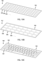
- FIGS. 10A-10C show example localized force sensing system that may be used in conjunction with the keyboard 100 (or any other suitable input device or electronic device).
- the force sensing systems shown in FIGS. 10A-10C use strain gauges to determine an amount of force applied to an input surface.
- the strain gauges can be used to determine an amount of deflection or deformation of an input surface (e.g., the cover 104), which can then be correlated to an amount of force associated with the input.
- FIG. 10A shows an example force sensing system 1001 that includes a substrate 1002.
- the substrate 1002 may correspond to the cover 104 in FIG. 1 , or it may correspond to a component that may be disposed below (e.g., coupled to a bottom of) a cover such as the cover 104.
- the substrate 1002 may be formed from or include any suitable material, such as glass, polymer, flexible circuit material, polyester film, or the like.
- the force sensing system 1001 includes strain gauges 1004 applied to or otherwise integrated with the substrate 1002.
- the strain gauges 1004 may be any suitable configuration and may be formed of any suitable material.
- the strain gauges 1004 may include a conductor having a serpentine or coil pattern (or any other suitable pattern) and disposed on a film or other substrate.
- the strain gauges 1004 may include at two or more substrates or films, each having a coiled or serpentine conductor and laminated with one another. This configuration may facilitate filtering or rejection of noise, interference, or other undesirable effects on the strain gauges 1004 caused by temperature, magnetic fields, or the like.
- the strain gauges 1004 may have any suitable size and may be arranged on the substrate 1002 in any suitable pattern.
- the strain gauges 1004 may all be substantially the same size and arranged in a regular grid pattern on the substrate 1002.
- the strain gauges 1004 may have any suitable size as viewed from the top of the substrate 1002, such as about 10 x 10 mm, 15 x 15 mm, or any other suitable size.
- the location of a force input on the substrate 1002 may be determined by analyzing signals from multiple (e.g., all) of the strain gauges 1004 to identify an estimated location (e.g., a centroid) of the input, regardless of where the input is applied on the substrate 1002 or other associated input surface.
- respective strain gauges 1004 may be positioned to correspond to respective keys or input regions.
- FIG. 10B shows a force sensing system 1009 in which a pattern of strain gauges 1005 on a substrate 1003 essentially mimics a pattern of keys or input regions, such that each key or input region of a keyboard has at least one strain gauge 1005 disposed thereunder. Accordingly, a force measured by a given strain gauge 1005 can be used to independently determine whether a corresponding key or input region has been actuated by a user, without reference to strain gauges associated with other keys or input regions.
- the substrate 1003 (which may correspond to the cover 104 or a component that is disposed below a cover) may include ribs 1007 formed on or otherwise coupled to the substrate 1003.
- the ribs 1007 may help isolate deformations and/or deflections produced by force and/or touch inputs applied to the substrate 1003 or an overlying cover, as shown and described in greater detail with respect to FIG. 11B .
- a device includes an adaptable display to produce virtual input regions at different locations on a cover 104, such ribs may be omitted to facilitate more uniform force sensing over the surface of the input surface.
- FIG. 10C shows a force sensing system 1011 having a pattern of strain gauges 1008 that are larger than those shown in FIG. 10A , illustrating another example arrangement of strain gauges on a substrate for a force sensing system. While the strain gauges 1008 are larger than those shown in FIG. 10A , they may still provide suitable resolution for determining the location of a force input.
- detecting and analyzing signals from multiple strain gauges 1008 e.g., to determine a centroid of a force input
- FIG. 11A shows a partial cross-sectional view of the keyboard 100 (e.g., viewed along line A-A in FIG. 1 ), illustrating an example in which the force sensing system 1001 ( FIG. 10A ) is incorporated in the keyboard 100.
- a finger 1105 is applying a force to the substrate 1002 (which may correspond to the cover 104), producing a local depression 1102 in the substrate 1002.
- the strain gauges 1006 that are coupled to the depressed region of the substrate 1002 may produce a signal or other detectable phenomenon corresponding to the relative amount of deflection and/or strain experienced by the substrate 1002 due to the deformation.
- a magnitude of the force input applied by the finger 1105 may be determined, as well as a location of the force input.
- the keyboard 100 in FIG. 11A shows a lower component 1106, which may correspond to the enclosure 102 or another internal component or structure of an electronic device.
- the substrate 1002 may be separated from the lower component 1106 by a gap 1104.
- the gap 1104 may be empty (e.g., it may be an air gap), or it may be fully or partially filled with a material, such as a compliant material similar to the compliant material 704 described with respect to FIGS. 7A -7C (e.g., foam, gel, silicone, an array of compliant material dots or structures (e.g., formed from silicone), or the like).
- the compliant material may help support the substrate 1002 and may help to localize and/or isolate deflections of the substrate 1002 caused by force inputs.
- FIG. 11B shows a partial cross-sectional view of the keyboard 100 (e.g., viewed along line A-A in FIG. 1 ), illustrating an example in which the force sensing system 1009 ( FIG. 10B ) is incorporated in the keyboard 100.
- a finger 1107 is applying a force to the substrate 1003 (which may correspond to the cover 104), producing a local depression 1108 in the substrate 1003.
- the force sensing system 1009 may include ribs 1007 formed on or otherwise coupled to the substrate 1003. The ribs may isolate and localize deflections of the substrate 1003 caused by force inputs. For example, as shown in FIG.
- the force input from the finger 1107 is largely contained between the ribs 1007-2 and 1007-3. Accordingly, the strain gauge 1005-3 may be subjected to a larger strain than nearby strain gauges (e.g., strain gauges 1005-2, 1005-4), thus reducing the likelihood of false detections of key presses at nearby or adjacent keys or input regions.
- nearby strain gauges e.g., strain gauges 1005-2, 1005-4
- the keyboard 100 in FIG. 11B shows a lower component 1112, which may correspond to the enclosure 102 or another internal component or structure of an electronic device.
- the substrate 1003 may be separated from the lower component 1112 by a gap 1110.
- the gap 1110 may be empty (e.g., it may be an air gap), or it may be fully or partially filled with a material, such as a compliant material similar to the compliant material 704 described with respect to FIGS. 7A -7C (e.g., foam, gel, silicone, an array of compliant material dots or structures (e.g., formed from silicone), or the like).
- the compliant material may help support the substrate 1003 and may help to further localize and/or isolate deflections of the substrate 1003 caused by force inputs.
- FIG. 12 shows a partial cross-sectional view of the keyboard 100 (e.g., viewed along line A-A in FIG. 1 ), showing a force-sensing system 1200 that uses an actuator 1201 to detect forces applied to a substrate 1208 (which may correspond to the cover 104).
- the keyboard 100 in FIG. 12 shows a lower component 1210, which may correspond to the enclosure 102 or another internal component or structure of an electronic device.
- the actuator 1201 may correspond to the haptic actuator 601 described herein.
- the actuator 1201 may provide both haptic actuation functions, as described above, as well as force sensing functions.
- the actuator 1201 (which may have the same construction as the haptic actuator 601) includes compliant layers 1206 sandwiched between electrode layers 1204.
- the electrode layers 1204 may be used as electrodes in a mutual-capacitance sensing scheme. For example, one electrode layer may be used as a drive electrode and another electrode layer may be used as a sense electrode.
- a processor or other circuitry may detect resulting electrical changes, which can be correlated to an amount of force applied via the force input. More particularly, the force-sensing system 1200 may use a force versus capacitance (or other electrical phenomenon) correlation to determine the amount of force that corresponds to a measured capacitance value (or other electrical value).
- an actuator may include 40 compliant layers 1206 and 41 electrode layers 1204. In such cases, all 41 electrodes may be used for capacitive sensing. Fewer electrodes may also be used.
- the actuator 1201 may detect applied forces and produce haptic outputs substantially simultaneously.
- a haptic signal may have a relatively low frequency (e.g., between 2 and 200 Hz, though other frequencies are also possible), while a drive signal for a drive electrode of a capacitive sensor may have a relatively high frequency (e.g., between 100 and 200 kHz, though other frequencies are also possible).
- a relatively low frequency e.g., between 2 and 200 Hz, though other frequencies are also possible
- a drive signal for a drive electrode of a capacitive sensor may have a relatively high frequency (e.g., between 100 and 200 kHz, though other frequencies are also possible).
- such frequencies may be applied to electrode layers of the actuator 1201 substantially simultaneously such that a haptic output is produced while electrical changes due to force inputs are also detected.
- Processors and/or circuitry of the force sensing system 1200 may compensate for any compression or extension of the compliant layers 1206 due to the haptic output when sensing force inputs
- a keyboard 100 includes force sensing regions that may be struck or actuated by more than one finger (such as a single force sensing region covering an entire keyboard or the force sensing pixels described above), the force sensing system may adjust or select a force threshold based on the number of fingers that are in contact with the surface.
- a typical force input indicative of a user attempting to actuate a virtual key on a flat surface may range from about 25 to about 150 grams. Accordingly, when a force sensing system detects a force input above that value, it should register a selection of the virtual key. However, if a user is resting multiple fingers on the surface of the keyboard, the force sensing system may detect a non-zero baseline force. This variability in the baseline force may result in false positive detections of force inputs, effectively lowering the amount of force necessary to trigger an input. As one example, if the baseline force due to three fingers resting on a keyboard is 20 grams, simply resting a fourth finger on the keyboard may be enough to cause the device to falsely identify a force input.
- the force sensing system may dynamically determine the force threshold that is indicative of a key press based on the number of fingers in contact with an input surface of the keyboard at a given time.
- FIG. 13 illustrates a graph 1300 showing three example baseline forces and force thresholds based on different numbers of fingers in contact with an input surface (e.g., the cover 104).
- the baseline force 1302 may correspond to a force of one finger resting on the surface.
- the force threshold is then set at a certain value 1306 above the baseline force 1302, resulting in the force threshold 1304.
- the baseline force 1308 may correspond to a force of two fingers resting on the surface, and the force threshold may be set at a certain value 1312 above the baseline force 1302, resulting in the force threshold 1310.
- the force threshold may be set at a certain value 1318 above the baseline force of 1314, resulting in the force threshold 1316.
- the force threshold is set between about 25 to about 150 grams higher than the baseline force, such as about 30 grams above the baseline force, regardless of the value of the baseline force.
- the force threshold may be set to different amounts above the baseline force, depending on the number of fingers that are in contact with the surface.
- the baseline forces 1302, 1308, and 1314 may be determined based on the number of fingers resting on the input surface of a keyboard.
- the baseline force corresponding to one finger resting on the surface may be determined to be 10 grams.
- the baseline force may be 10 grams regardless of any actual detected force applied to the surface.
- the baseline force may be 20 grams, and so on.
- the force threshold may be determined at any given time based on the number of fingers in contact with the input surface and without regard to an actual amount of force being applied to the surface by the fingers.
- FIG. 14 depicts an example process 1400 for detecting a key press on an input surface of an electronic device.
- the process 1400 may be implemented on any of the example devices discussed herein.
- the process 1400 may be used, for example, to determine what actions (if any) the electronic device should perform in response to the force input, and may be implemented using, for example, the processing unit and other hardware elements described with respect to FIG. 20 .
- the process 1400 may be implemented as processor-executable instructions that are stored within the memory of the electronic device.
- a number of fingers in contact with an input surface of an electronic device is determined.
- a touch sensing system of the keyboard 100 may be used to determine how many fingers are in contact with the cover 104.
- a force threshold indicative of a key press is determined.
- the keyboard 100 determines a force threshold that, if satisfied, will result in the keyboard 100 registering a selection of an input region (e.g., a virtual key).
- the force threshold is determined based at least in part on the number of fingers in contact with the input surface.
- the force threshold may be between about 25 and about 150 grams higher than a baseline force for the number of fingers determined to be in contact with the input surface.
- the baseline force for each finger in contact may be 10 grams.
- each additional finger in contact with the input surface may add another 10 grams to the baseline force.
- the baseline force for each number of fingers may not increase linearly.
- the baseline force for one finger may be 10 grams, and the baseline force for eight fingers may be 40 grams.
- a force input satisfying the force threshold is detected.
- the force input may be detected with a force sensing system, such as any of the force sensing systems described above.
- a selection of an input region may be registered. For example, if a force input satisfying the threshold is determined to have been applied to a location of a key, a selection of that key (which may correspond to a text character, for example), is registered.
- the keyboard 100 may communicate the selection to an electronic device, which may execute an appropriate action or response (such as inputting the text character into an application).
- a force threshold may instead or additionally be established based on the magnitude of detected force inputs. That is, different users may type or apply inputs to a keyboard with different forces. More particularly, a first user may type with a relative lower force for each key strike (e.g., with an average force of about 10 grams), while a second user may type with a relatively larger force for each key strike (e.g., with an average force of about 100 grams). Accordingly, the keyboard 100 may adapt to individual users by adjusting the force threshold after detecting a number of inputs.
- the keyboard 100 may detect inputs that are indicative of typing inputs (e.g., key presses), such as inputs applied to key regions and/or inputs having frequencies or other patterns indicative of key presses, and may determine average forces of those inputs. The keyboard 100 may then adjust the force threshold based on the average forces of the key presses. Thus, if the force threshold is significantly below a user's average typing force as detected by the keyboard 100, the keyboard 100 may mistake lighter touches (that were not intended as key presses) as key presses. On the other hand, if the force threshold is significantly above a user's average typing force as detected by the keyboard 100, the keyboard 100 may not recognize all of the user's inputs as key presses.
- key presses e.g., key presses
- the keyboard 100 may dynamically set the force threshold based on an average detected force input.
- the force threshold may be set to a predetermined amount below the average typing force, such as 1%, 5%, 10%, or 20% lower than the average typing force (or any other suitable value).
- the average typing force may be detected at any suitable interval, such as on a time-based periodic basis (e.g., every 1 hour, every 5 hours, etc.), or on an event-based basis (e.g., every time a word-processing application is opened, every time a computer is restarted, etc.). Other intervals, periods, and triggering events are also contemplated.
- a time-based periodic basis e.g., every 1 hour, every 5 hours, etc.
- an event-based basis e.g., every time a word-processing application is opened, every time a computer is restarted, etc.
- Other intervals, periods, and triggering events are also contemplated.
- a keyless keyboard may also include a touch sensing system that detects touch and/or motion-based inputs (e.g., swipes, pinches, rotations, or taps), similar to a trackpad. Accordingly, a touch input corresponding to a movement across the input surface may be detected. In response to detecting the touch input corresponding to the movement across the input surface, a position of a cursor on a display of an electronic device may be changed.
- the touch sensing system may share the same input surface as the keys of the keyboard, such that a user can interact with the surface of the flat keyboard in various ways, including typing (e.g., force inputs) and traditional trackpad inputs (e.g., swipes, pinches, rotations, taps, and the like).
- the keyboard 100 may include an adaptable display that can change the layout of the keys (e.g., virtual keys) on the surface of the keyboard 100.
- FIGS. 15A-17 illustrate example layouts and other functions that may be implemented in a keyboard 100 that includes both force sensing and haptic outputs.
- an input device 1500 may detect the location of a user's fingers 1532 and define multiple input regions according to where and how the user places his or her fingers 1532. This may improve user experience by allowing varying arrangements, sizes, and positions of the input regions (or keys) 1506.
- the input surface 1504 may initially be inactive, with no defined input regions or visual indications of the input regions. As a user's fingers 1532 approach the input surface 1504, the input surface 1504 may become active as shown in FIG. 15B .
- the input surface 1504 may incorporate proximity sensors, such as touch sensing systems, which detect the presence and/or location of the user's fingers 1532. These sensors may detect a desired location for defining the input regions 1506.
- the input regions 1506 may alternatively be defined in response to additional user action, such as the performance of a gesture, touching of the input surface 1504, or pressing of the input surface 1504.
- the input regions 1506 may be indicated visually.
- a display within the input surface 1504 may visually indicate the location of the virtual keys 1506.
- the locations of the virtual keys 1506 may also or instead be indicated tactilely.
- actuators e.g., piezoelectric actuators, electrostatic elements, etc.
- no haptic output may be provided.
- the actuator may produce an output, thus indicating to the user that their finger is on a key boundary.
- the location of the input regions and corresponding visual indicia of the input regions may further be adaptive according to user interaction.
- the input device 1500 may further include computer-readable memory storing multiple keyboard layouts, each of which has a corresponding visual representation.
- the layout depicted in FIG. 15B may be a first layout (e.g., a first configuration of virtual keys), while FIG. 15C may be a second layout (e.g., a second configuration of virtual keys). Additional layouts may also be stored within the input device 1500, or may be transmitted to the input device 1500 by another computing device.
- the input regions 1506 may be differently defined (e.g., according to a second keyboard layout). As illustrated in FIG. 15C , a user's fingers are placed on a previously inactive input surface at an angle to each other rather than a straight line as depicted in FIG. 15B .
- the input device may recognize this placement as corresponding to an ergonomic keyboard layout (e.g., a second stored keyboard layout), and define input regions 1506 and corresponding visual indicia of the input regions accordingly.
- FIG. 16 depicts an example input device 1600 incorporated within a notebook or laptop computer 1642 in which an alternative user input is produced on an adaptive input surface 1604.
- the notebook computer 1642 comprises an enclosure 1602 having an upper portion with a display 1644 and a lower portion housing an input device 1600.
- the enclosure may further house various components, such as a processing unit (which may be shared with the processing unit of the input device 1600 or may be separate), memory, computer-readable media, input/output ports, sensors, microphones, speakers, etc.
- the input device 1600 may include a force sensing system, a touch sensing system, and one or more haptic actuators (not shown). Any of the force or touch sensing systems or haptic actuators described herein may be used in the input device 1600.
- the input device 1600 has an adaptive input surface 1604 (which may correspond to the cover 104 in FIG. 1 or any other cover described herein).
- the input surface 1604 is shown adapted to interact with an active software application rendered on the display 1644 of the notebook computer 1642; here, a music player.
- the input surface 1604 has defined input regions, including media playback controls 1646 and a virtual trackpad 1648.
- the input surface 1604 also defines an input region for volume control 1650.
- the touch and/or force sensing systems of the input device 1600 may detect the motion of the user's finger 1632, and the haptic actuators may be activated (e.g., caused to oscillate or vibrate the input surface 1604) and provide haptic feedback to the user.
- the haptic feedback may increase in intensity (e.g., frequency or amplitude) as the finger 1632 slides to increase volume, and the intensity of the haptic feedback may decrease as the finger 1632 slides to decrease volume.
- FIG. 17 depicts an example input device 1700 incorporated within a notebook computer 1742.
- the notebook computer 1742 comprises an enclosure 1702 having an upper portion with a display 1744 and a lower portion housing an input device 1700 according to the present invention.
- the input device 1700 has an adaptive input surface 1704 (which may correspond to the cover 104 in FIG. 1 or any other cover described herein).
- the input surface 1704 is shown adapted to interact with a user interface of a software application rendered on the display 1744 of the notebook computer 1742; here, a web browser.
- a web browser Assuming that the input surface 1704 previously defined a standard keyboard layout comprising virtual keys, as the web browser is opened the virtual keys 1706 may be shifted and/or truncated while a virtual trackpad 1748 may be repositioned to the center of the input surface 1704. With the virtual trackpad 1748 more prominently located, a user 1732 may more easily navigate web pages which may frequently require moving a pointer 1752 and clicking links.
- an input device such as a keyless keyboard
- Input devices may be incorporated into devices such as a notebook computer, as shown above with respect to FIGS. 16 and 17 , or they may be separate devices in communication with a host computer or other device as illustrated with respect to FIGS. 18-19 .
- FIG. 18 depicts an example keyboard 1800 in communication with a desktop computer 1854.
- the keyboard 1800 may be in communication with the desktop computer 1854 through a wired or wireless connection.
- the keyboard 1800 has an enclosure and an adaptive input surface 1804 positioned within the enclosure.
- the input surface 1804 defines an input region 1812, which may correspond to a character input key.
- the keyboard 1800 may include force sensing systems and/or haptic actuators or haptic output systems described herein.
- FIG. 19 depicts an example input device 1900 incorporated into a cover case.
- the cover case may be attached to and in communication with a portable tablet computing device 1956.
- the input device 1900 may be in communication with the tablet 1956 through a wired connection, an electrical contact connection, or a wireless connection.
- the input device 1900 has an adaptive input surface 1904 which defines an input region 1912.
- the input device 1900 may include force sensing systems and/or haptic actuators or haptic output systems described herein.
- FIG. 20 depicts example components of an input device in accordance with the embodiments described herein.
- the schematic representation depicted in FIG. 20 may correspond to components of the devices depicted herein.
- FIG. 20 may also more generally represent other types of devices that include force sensing systems and controllable haptic feedback elements in accordance with the embodiments described herein.
- a device 2000 includes a processing unit 2058 operatively connected to computer memory 2060.
- the processing unit 2058 may be operatively connected to the memory 2060 component via an electronic bus or bridge.
- the processing unit 2058 may include one or more computer processors or microcontrollers that are configured to perform operations in response to computer-readable instructions. Where incorporated into a larger device such as a notebook computer, the processing unit 2058 may be the central processing unit (CPU) of the larger device. Additionally or alternatively, the processing unit 2058 may include other processors within the device 2000 including application specific integrated chips (ASIC) and other microcontroller devices.
- ASIC application specific integrated chips
- the memory 2060 may include a variety of types of non-transitory computer-readable storage media, including, for example, read access memory (RAM), read-only memory (ROM), erasable programmable memory (e.g., EPROM and EEPROM), or flash memory.
- RAM read access memory
- ROM read-only memory
- EPROM erasable programmable memory
- flash memory any type of non-transitory computer-readable storage media, including, for example, read access memory (RAM), read-only memory (ROM), erasable programmable memory (e.g., EPROM and EEPROM), or flash memory.
- the memory 2060 is configured to store computer-readable instructions, sensor values, and other persistent software elements.
- the processing unit 2058 is operable to read computer-readable instructions stored on the memory 2060.
- the computer-readable instructions may adapt the processing unit 2058 to perform the operations or functions described herein.
- the computer-readable instructions may be provided as a computer-program product, software application, or the like.
- the device 2000 may also include a battery 2062 that is configured to provide electrical power to the components of the device 2000.
- the battery 2062 may include one or more power storage cells that are linked together to provide an internal supply of electrical power.
- the battery 2062 may be operatively coupled to power management circuitry that is configured to provide appropriate voltage and power levels for individual components or groups of components within the device 2000.
- the battery 2062 via power management circuitry, may receive power from an external source, such as an AC power outlet.
- the battery 2062 may store received power so that the device 2000 may operate without connection to an external power source for an extended period of time, which may range from several hours to several days.
- the device 2000 may also include a display 2020 (or multiple displays 2020).
- the display 2020 may include a liquid crystal display (LCD), organic light emitting diode (OLED) display, electroluminescent (EL) display, electrophoretic ink (e-ink) display, or the like. If the display 2020 is an LCD or e-ink type display, the display 2020 may also include a backlight component that can be controlled to provide variable levels of display brightness. If the display 2020 is an OLED or EL type display, the brightness of the display 2020 may be controlled by modifying the electrical signals that are provided to display elements.
- the display 2020 may include a standalone display such as the display 1744 ( FIG. 17 ), and/or an adaptive display of a keyboard or other input device. For example, a display 2020 may be incorporated into a keyboard to present various keyboard layouts or other user interfaces.
- the device 2000 includes one or more input devices 2064.
- the input device 2064 is a device that is configured to receive user input.
- the input device 2064 may include, for example, a push button, a touch-activated button, or the like.
- the input device 2064 may provide a dedicated or primary function, including, for example, a power button, volume buttons, home buttons, scroll wheels, and camera buttons.
- a touch sensing system and a force sensing system may also be classified as input devices.
- touch sensing system touch sensing element 2018 and touch sensing circuitry 2070
- force sensing system force sensing element 2066 and force sensing circuitry 2072
- the device 2000 may include a touch sensing system (or multiple touch sensing systems).
- a touch sensing system may include a touch sensing element 2018, or multiple touch sensing elements 2018, and touch sensing circuitry 2070.
- the touch sensing system may also include or incorporate other components of an electronic device, such as a cover or input surface of an electronic device.
- the touch sensing element(s) 2018 may include electrodes, electrode layers, or other components, and may be configured to operate in accordance with a mutual-capacitance or self-capacitance touch-sensing scheme, as described above.
- Touch sensing element(s) 2018 for other types of touch sensing schemes may additionally or alternatively be used, such as elements for surface acoustic wave sensors, resistive sensors, infrared sensors, and the like.
- the device 2000 may also include touch sensing circuitry 2070.
- the touch sensing circuitry 2070 may be operably coupled to the touch sensing element(s) 2018 to form all or part of the touch sensing system.
- the touch sensing circuitry 2070 in conjunction with the touch sensing element(s) 2018, may detect and estimate the location of a touch on or near an input surface (such as an input surface of a keyless keyboard).
- the touch sensing circuitry 2070 may further output signals or other indicia indicating the detected location of a touch.
- the touch sensing circuitry 2070 may further be operably coupled to the processing unit 2058.
- the device 2000 may also include a force sensing system (or multiple force sensing systems).
- a force sensing system may correspond to any component or group of components that detects and/or estimates an amount of force applied to an input surface.
- a force sensing system may include a force sensing element 2066, or multiple force sensing elements 2066, and force sensing circuitry 2072.
- the force sensing system may also include or incorporate other components of an electronic device, such as a cover or input surface of an electronic device.
- each force sensing system may include its own separate components (e.g., each may have a different force sensing element and force sensing circuitry), or they may share some components (e.g., each force sensing system may each have its own force sensing element, but may share force sensing circuitry).
- the force sensing element(s) 2066 may produce changes in electrical values (e.g., resistance, capacitance, voltage, etc.), detectible signals, or the like, in response to force inputs applied to the keyless keyboard (or other force-sensitive input device).
- the sensing element(s) 2066 may be implemented as one or more layers, such as layers of electrodes or other conductive materials.
- Example force sensitive elements are described above, and may include capacitive sensing elements, electrodes, piezoelectric materials, strain gauges, and the like.
- the force sensing circuitry 2072 may be operably coupled to the force sensing element 2066 to form all or part of the force sensing system.
- the force sensing circuitry 2072 in conjunction with the force sensing element(s) 2066, may detect and estimate an amount of force applied to an input surface.
- the force sensing circuitry 2072 may further detect a location of an applied force.
- the force sensing circuitry 2072 may further output signals or other indicia indicating an estimated amount of applied force.
- the force sensing circuitry 2072 may operate using a dynamic or adjustable force threshold.
- the force sensing circuitry 2072 may only output signals in accordance with an applied force exceeding the force threshold.
- the force sensing circuitry 2072 may further be operably coupled to the processing unit 2058.
- the device 2000 may also include a haptic actuator 2026 (or multiple haptic actuators 2026).
- the haptic actuator 2026 may be controlled by the processing unit 2058, and may provide haptic feedback to a user interacting with the device 2000, such as illustrated above with respect to FIGS. 2-6C .
- multiple haptic actuators 2026 may provide localized macro haptic feedback at different areas of an input surface.
- the device 2000 may also include a communication port 2068 that is configured to transmit and/or receive signals or electrical communication from an external or separate device.
- the communication port 2068 may couple to an external device via a cable, adaptor, or other type of electrical connector.
- the communication port 2068 may be used to couple the device 2000 to a host computer.
- the communication port 2068 may receive control information from an external device, which may be used to operate and/or control the device 2000.
Landscapes
- Engineering & Computer Science (AREA)
- General Engineering & Computer Science (AREA)
- Theoretical Computer Science (AREA)
- Human Computer Interaction (AREA)
- Physics & Mathematics (AREA)
- General Physics & Mathematics (AREA)
- Input From Keyboards Or The Like (AREA)
- User Interface Of Digital Computer (AREA)
Applications Claiming Priority (3)
| Application Number | Priority Date | Filing Date | Title |
|---|---|---|---|
| US201662393989P | 2016-09-13 | 2016-09-13 | |
| PCT/US2017/051059 WO2018052871A1 (fr) | 2016-09-13 | 2017-09-12 | Clavier sans clé avec détection de force et rétroaction haptique |
| EP17772541.3A EP3420438A1 (fr) | 2016-09-13 | 2017-09-12 | Clavier sans clé avec détection de force et rétroaction haptique |
Related Parent Applications (1)
| Application Number | Title | Priority Date | Filing Date |
|---|---|---|---|
| EP17772541.3A Division EP3420438A1 (fr) | 2016-09-13 | 2017-09-12 | Clavier sans clé avec détection de force et rétroaction haptique |
Publications (2)
| Publication Number | Publication Date |
|---|---|
| EP4242801A2 true EP4242801A2 (fr) | 2023-09-13 |
| EP4242801A3 EP4242801A3 (fr) | 2023-11-22 |
Family
ID=59966849
Family Applications (2)
| Application Number | Title | Priority Date | Filing Date |
|---|---|---|---|
| EP17772541.3A Withdrawn EP3420438A1 (fr) | 2016-09-13 | 2017-09-12 | Clavier sans clé avec détection de force et rétroaction haptique |
| EP23178477.8A Pending EP4242801A3 (fr) | 2016-09-13 | 2017-09-12 | Clavier sans clé avec détection de force et rétroaction haptique |
Family Applications Before (1)
| Application Number | Title | Priority Date | Filing Date |
|---|---|---|---|
| EP17772541.3A Withdrawn EP3420438A1 (fr) | 2016-09-13 | 2017-09-12 | Clavier sans clé avec détection de force et rétroaction haptique |
Country Status (5)
| Country | Link |
|---|---|
| US (2) | US11500538B2 (fr) |
| EP (2) | EP3420438A1 (fr) |
| JP (3) | JP6846079B2 (fr) |
| CN (2) | CN108885512B (fr) |
| WO (1) | WO2018052871A1 (fr) |
Cited By (1)
| Publication number | Priority date | Publication date | Assignee | Title |
|---|---|---|---|---|
| SE2450899A1 (en) * | 2023-09-19 | 2025-03-20 | Peratech Ip Ltd | Force Sensor Apparatus and Keyboard |
Families Citing this family (65)
| Publication number | Priority date | Publication date | Assignee | Title |
|---|---|---|---|---|
| US9502193B2 (en) | 2012-10-30 | 2016-11-22 | Apple Inc. | Low-travel key mechanisms using butterfly hinges |
| US9710069B2 (en) | 2012-10-30 | 2017-07-18 | Apple Inc. | Flexible printed circuit having flex tails upon which keyboard keycaps are coupled |
| JP6313339B2 (ja) | 2013-02-06 | 2018-04-18 | アップル インコーポレイテッド | 動的に調整可能な外観及び機能を有する入力/出力デバイス |
| WO2014193850A1 (fr) | 2013-05-27 | 2014-12-04 | Apple Inc. | Ensemble interrupteur à course réduite |
| US9908310B2 (en) | 2013-07-10 | 2018-03-06 | Apple Inc. | Electronic device with a reduced friction surface |
| WO2015047606A1 (fr) | 2013-09-30 | 2015-04-02 | Apple Inc. | Dessus de touche à épaisseur réduite |
| US10796863B2 (en) | 2014-08-15 | 2020-10-06 | Apple Inc. | Fabric keyboard |
| US10082880B1 (en) | 2014-08-28 | 2018-09-25 | Apple Inc. | System level features of a keyboard |
| US9870880B2 (en) | 2014-09-30 | 2018-01-16 | Apple Inc. | Dome switch and switch housing for keyboard assembly |
| CN205959841U (zh) | 2015-05-13 | 2017-02-15 | 苹果公司 | 电子设备和键盘组件 |
| US9997308B2 (en) | 2015-05-13 | 2018-06-12 | Apple Inc. | Low-travel key mechanism for an input device |
| JP6637070B2 (ja) | 2015-05-13 | 2020-01-29 | アップル インコーポレイテッドApple Inc. | 電子デバイス用のキーボード |
| US11334197B2 (en) * | 2015-07-27 | 2022-05-17 | Jordan A. Berger | Universal keyboard |
| US9971084B2 (en) | 2015-09-28 | 2018-05-15 | Apple Inc. | Illumination structure for uniform illumination of keys |
| US10353485B1 (en) | 2016-07-27 | 2019-07-16 | Apple Inc. | Multifunction input device with an embedded capacitive sensing layer |
| US10115544B2 (en) | 2016-08-08 | 2018-10-30 | Apple Inc. | Singulated keyboard assemblies and methods for assembling a keyboard |
| US10755877B1 (en) | 2016-08-29 | 2020-08-25 | Apple Inc. | Keyboard for an electronic device |
| US11409375B2 (en) | 2016-11-11 | 2022-08-09 | Pixart Imaging Inc. | Method and apparatus for adjusting optical setting of optical input device and related optical input device |
| TWI742011B (zh) * | 2016-11-11 | 2021-10-11 | 原相科技股份有限公司 | 用於設定光學輸入裝置的方法與設定裝置以及相關光學輸入系統 |
| TWI645284B (zh) * | 2016-12-28 | 2018-12-21 | 仁寶電腦工業股份有限公司 | 電子裝置及控制風扇運轉的方法 |
| CN108804000B (zh) * | 2017-04-26 | 2021-07-27 | 深圳富泰宏精密工业有限公司 | 电子装置及外接显示器操作方法 |
| CN117270637A (zh) | 2017-07-26 | 2023-12-22 | 苹果公司 | 具有键盘的计算机 |
| US11635890B2 (en) * | 2017-12-19 | 2023-04-25 | Gail Elizabeth Davis | Keyboard having improved alphabet key arrangement |
| US10747332B2 (en) * | 2018-09-13 | 2020-08-18 | Apple Inc. | Flexible stabilized button input device |
| CN109068087B (zh) * | 2018-09-14 | 2020-04-21 | 大连成者科技有限公司 | 智能会议投影系统 |
| US10831346B2 (en) * | 2018-10-30 | 2020-11-10 | International Business Machines Corporation | Ergonomic and sensor analysis based user experience design |
| US10831290B2 (en) * | 2019-02-22 | 2020-11-10 | Qualcomm Incorporated | Stylus-tracking piezoelectric sensor |
| CN111857392A (zh) * | 2019-04-26 | 2020-10-30 | 富泰华工业(深圳)有限公司 | 触控感测模组及应用其的电子装置 |
| JP2020204825A (ja) * | 2019-06-14 | 2020-12-24 | シャープ株式会社 | タッチ入力システム、タッチ入力装置、および、タッチ入力補助ツール |
| CN110231890B (zh) * | 2019-06-28 | 2022-04-29 | 京东方科技集团股份有限公司 | 一种压力感应器件、显示面板及其制作方法、显示设备 |
| CN110737328A (zh) * | 2019-08-27 | 2020-01-31 | 晟光科技股份有限公司 | 一种玻璃触控键盘的加工工艺 |
| CN112600961A (zh) * | 2019-09-19 | 2021-04-02 | 华为技术有限公司 | 一种音量调节方法及电子设备 |
| US20220283641A1 (en) * | 2019-11-08 | 2022-09-08 | Hewlett-Packard Development Company, L.P. | Keyboards with haptic outputs |
| US11860052B2 (en) * | 2019-12-19 | 2024-01-02 | Toyota Motor Engineering & Manufacturing North America, Inc. | Pressure distribution and localization detection methods and apparatuses incorporating the same |
| US20220197412A1 (en) * | 2019-12-25 | 2022-06-23 | Yuhei AKATSUKA | Input device, input method |
| US11662820B2 (en) | 2020-01-08 | 2023-05-30 | Dell Products, Lp | System for a solid-state keyboard and touchpad providing haptic feedback |
| US10860112B1 (en) | 2020-01-31 | 2020-12-08 | Dell Products, Lp | System for a solid-state keyboard and touchpad with a single sheet cover for providing haptic feedback |
| US11294469B2 (en) | 2020-01-31 | 2022-04-05 | Dell Products, Lp | System and method for processing user input via a reconfigurable haptic interface assembly for displaying a modified keyboard configuration |
| US11093048B1 (en) | 2020-01-31 | 2021-08-17 | Dell Products, Lp | System for modified key actions and haptic feedback for smart typing assist with a solid-state keyboard and touchpad |
| US11079849B1 (en) | 2020-01-31 | 2021-08-03 | Dell Products, Lp | System for extended key actions and haptic feedback and optimized key layout for a solid-state keyboard and touchpad |
| US11301053B2 (en) | 2020-01-31 | 2022-04-12 | Dell Products, Lp | System for providing haptic feedback across full palm rest in fixed position of information handling system |
| US11175745B2 (en) | 2020-01-31 | 2021-11-16 | Dell Products, Lp | System and method for application of piezo electric haptic keyboard personal typing profile |
| US11067269B1 (en) | 2020-01-31 | 2021-07-20 | Dell Products, Lp | System and method for backlight integration with electrical contact foil in piezoelectric haptic keyboard |
| US11106772B2 (en) | 2020-01-31 | 2021-08-31 | Dell Products, Lp | System and method for continuous user identification via piezo haptic keyboard and touchpad dynamics |
| US10936073B1 (en) | 2020-01-31 | 2021-03-02 | Dell Products, Lp | System and method for generating high-frequency and mid-frequency audible sound via piezoelectric actuators of a haptic keyboard |
| US11106286B2 (en) | 2020-01-31 | 2021-08-31 | Dell Products, Lp | System and method for mood detection via piezo haptic keyboard dynamics |
| US11579695B2 (en) | 2020-01-31 | 2023-02-14 | Dell Products, Lp | System and method for generating sound effects on fingertips with piezoelectric actuators of a haptic keyboard |
| US11079816B1 (en) | 2020-01-31 | 2021-08-03 | Dell Products, Lp | System and method for vapor chamber directional heat dissipation for a piezoelectric keyboard assembly |
| US11216182B2 (en) * | 2020-03-03 | 2022-01-04 | Intel Corporation | Dynamic configuration of a virtual keyboard |
| US11836297B2 (en) | 2020-03-23 | 2023-12-05 | Apple Inc. | Keyboard with capacitive key position, key movement, or gesture input sensors |
| KR102256042B1 (ko) * | 2020-10-13 | 2021-05-25 | 삼성전자 주식회사 | 입력을 유도하는 전자 장치 및 방법. |
| CN114489311B (zh) * | 2020-10-23 | 2024-03-15 | 京东方科技集团股份有限公司 | 触觉反馈结构及制作方法、触摸显示面板、触摸显示装置 |
| US12169595B2 (en) * | 2021-05-26 | 2024-12-17 | Huawei Technologies Co., Ltd. | Methods, devices, and computer-readable storage media for performing a function based on user input |
| US12422930B2 (en) * | 2021-05-31 | 2025-09-23 | Beijing Boe Technology Development Co., Ltd. | Display device |
| CN113515197B (zh) * | 2021-06-30 | 2024-08-09 | 中国长城科技集团股份有限公司 | 键盘及电子设备 |
| WO2023035029A1 (fr) * | 2021-09-09 | 2023-03-16 | Flux Group Pty Ltd | Dispositif d'entrée informatique |
| CN116134404B (zh) * | 2021-09-15 | 2026-01-30 | 京东方科技集团股份有限公司 | 触感生成方法、触觉再现装置及计算机存储介质 |
| US11513600B1 (en) | 2021-10-04 | 2022-11-29 | Dell Products, L.P. | Information handling system glass keyboard with deflection and haptic feedback |
| US11954256B2 (en) * | 2021-12-17 | 2024-04-09 | Google Llc | Haptic interface for computing devices |
| US11662822B1 (en) | 2021-12-20 | 2023-05-30 | Huawei Technologies Co., Ltd. | Systems and methods for generating pseudo haptic feedback |
| KR20230123534A (ko) * | 2022-02-16 | 2023-08-24 | 삼성디스플레이 주식회사 | 표시 장치 및 이를 포함하는 터치 입력 시스템 |
| US11656685B1 (en) | 2022-04-27 | 2023-05-23 | Dell Products L.P. | Information handling system keyboard with haptic enhanced membrane trigger |
| US11733743B1 (en) * | 2022-07-14 | 2023-08-22 | Dell Products L.P. | Computer tactile pad mechanism |
| US12105881B2 (en) | 2022-12-29 | 2024-10-01 | Qualcomm Incorporated | On-screen keyboard user interface with context-aware haptic feedback |
| US12254135B2 (en) * | 2023-03-28 | 2025-03-18 | Sensel, Inc. | Simulation of a physical interface utilizing touch tracking, force sensing, and haptic feedback |
Family Cites Families (539)
| Publication number | Priority date | Publication date | Assignee | Title |
|---|---|---|---|---|
| US3657492A (en) | 1970-09-25 | 1972-04-18 | Sperry Rand Corp | Keyboard apparatus with moisture proof membrane |
| FR2147420A5 (fr) | 1971-07-27 | 1973-03-09 | Arvai T | |
| GB1361459A (en) | 1971-08-05 | 1974-07-24 | Standard Telephones Cables Ltd | Electrical contact units |
| JPS5329226B2 (fr) | 1973-08-23 | 1978-08-19 | ||
| JPS5617629B2 (fr) | 1974-02-21 | 1981-04-23 | ||
| US3978297A (en) | 1975-03-31 | 1976-08-31 | Chomerics, Inc. | Keyboard switch assembly with improved pushbutton and associated double snap acting actuator/contactor structure |
| DE7521482U (de) | 1975-07-05 | 1978-07-06 | Licentia Patent-Verwaltungs-Gmbh, 6000 Frankfurt | Tastschalter mit Tellerfeder |
| US4095066A (en) | 1976-08-04 | 1978-06-13 | International Business Machines Corporation | Hinged flyplate actuator |
| DE2902769C2 (de) | 1979-01-25 | 1982-12-09 | Rudolf Schadow Gmbh, 1000 Berlin | Drucktastenschalter |
| US4319099A (en) | 1979-05-03 | 1982-03-09 | Atari, Inc. | Dome switch having contacts offering extended wear |
| DE3002772C2 (de) | 1980-01-26 | 1984-03-01 | Leopold Kostal GmbH & Co KG, 5880 Lüdenscheid | Tastschalter in einer elektrischen Leiterplatte |
| JPS5923119U (ja) | 1982-08-03 | 1984-02-13 | アルプス電気株式会社 | 押釦スイツチ |
| JPS59171414A (ja) | 1983-03-19 | 1984-09-27 | 九州日立マクセル株式会社 | キ−トツプの製造方法 |
| US4670084A (en) | 1983-06-20 | 1987-06-02 | David Durand | Apparatus for applying a dye image to a member |
| JPS6055477A (ja) | 1983-09-07 | 1985-03-30 | Agency Of Ind Science & Technol | 一様重み線形フィルタ回路 |
| US4598181A (en) | 1984-11-13 | 1986-07-01 | Gte Communication Systems Corp. | Laminate switch assembly having improved tactile feel and improved reliability of operation |
| US4596905A (en) | 1985-01-14 | 1986-06-24 | Robertshaw Controls Company | Membrane keyboard construction |
| JPS61172422A (ja) | 1985-01-25 | 1986-08-04 | Matsushita Electric Works Ltd | ブ−スタ− |
| US5136131A (en) | 1985-05-31 | 1992-08-04 | Sharp Kabushiki Kaisha | Push-button switch including a sheet provided with a plurality of domed members |
| JPS6233123U (fr) | 1985-08-14 | 1987-02-27 | ||
| JPS6272429A (ja) | 1985-09-26 | 1987-04-03 | Kawasaki Steel Corp | 厚鋼板の熱間矯正方法 |
| JP2630383B2 (ja) | 1986-04-09 | 1997-07-16 | アルプス電気株式会社 | キートッップの製造方法 |
| JPS63182024A (ja) | 1987-01-22 | 1988-07-27 | Nitsukuu Kogyo Kk | 混合撹拌機 |
| US5021638A (en) | 1987-08-27 | 1991-06-04 | Lucas Duraltih Corporation | Keyboard cover |
| JPH01174820U (fr) | 1988-05-30 | 1989-12-12 | ||
| US4987275A (en) | 1989-07-21 | 1991-01-22 | Lucas Duralith Corporation | Multi-pole momentary membrane switch |
| EP0441993A1 (fr) | 1990-02-12 | 1991-08-21 | Lexmark International, Inc. | Plaque d'actionnement pour un clavier |
| JPH0422024A (ja) | 1990-05-15 | 1992-01-27 | Fujitsu Ltd | キーボード |
| DE69118314T2 (de) | 1990-10-30 | 1996-10-24 | Teikoku Tsushin Kogyo Kk | Tastschalter und Taste |
| FI88345C (fi) | 1991-01-29 | 1993-04-26 | Nokia Mobile Phones Ltd | Belyst tastatur |
| US5092459A (en) | 1991-01-30 | 1992-03-03 | Daniel Uljanic | Cover for remote control unit |
| JPH0520963A (ja) | 1991-07-11 | 1993-01-29 | Shizuoka Prefecture | 感圧導電接点 |
| JPH0524512A (ja) | 1991-07-19 | 1993-02-02 | Fuji Heavy Ind Ltd | 自動車用簡易型車速感応ワイパ装置 |
| US5278372A (en) | 1991-11-19 | 1994-01-11 | Brother Kogyo Kabushiki Kaisha | Keyboard having connecting parts with downward open recesses |
| JP3200975B2 (ja) | 1992-06-04 | 2001-08-20 | ブラザー工業株式会社 | キースイッチ装置 |
| JP2577359Y2 (ja) | 1992-06-09 | 1998-07-23 | ブラザー工業株式会社 | キースイッチ装置 |
| US5340955A (en) | 1992-07-20 | 1994-08-23 | Digitran Company, A Division Of Xcel Corp. | Illuminated and moisture-sealed switch panel assembly |
| US5481074A (en) | 1992-08-18 | 1996-01-02 | Key Tronic Corporation | Computer keyboard with cantilever switch and actuator design |
| US5422447A (en) | 1992-09-01 | 1995-06-06 | Key Tronic Corporation | Keyboard with full-travel, self-leveling keyswitches and return mechanism keyswitch |
| US5397867A (en) | 1992-09-04 | 1995-03-14 | Lucas Industries, Inc. | Light distribution for illuminated keyboard switches and displays |
| JPH0736296B2 (ja) | 1992-10-01 | 1995-04-19 | 九州日立マクセル株式会社 | キートップの製造方法 |
| US5504283A (en) | 1992-10-28 | 1996-04-02 | Brother Kogyo Kabushiki Kaisha | Key switch device |
| CN2155620Y (zh) | 1993-05-26 | 1994-02-09 | 陈道生 | 薄膜式键盘之机械式按键开关 |
| JP3201102B2 (ja) | 1993-11-05 | 2001-08-20 | ブラザー工業株式会社 | キースイッチ装置及びその組立方法 |
| US5457297A (en) | 1994-04-20 | 1995-10-10 | Chen; Pao-Chin | Computer keyboard key switch |
| US5875013A (en) | 1994-07-20 | 1999-02-23 | Matsushita Electric Industrial Co.,Ltd. | Reflection light absorbing plate and display panel for use in a display apparatus |
| US5421659A (en) | 1994-09-07 | 1995-06-06 | Liang; Hui-Hu | Keyboard housing with channels for draining spilled liquid |
| US5477430A (en) | 1995-03-14 | 1995-12-19 | Delco Electronics Corporation | Fluorescing keypad |
| US7109968B2 (en) | 1995-07-20 | 2006-09-19 | E Ink Corporation | Non-spherical cavity electrophoretic displays and methods and materials for making the same |
| JP3593184B2 (ja) * | 1995-07-28 | 2004-11-24 | 日本ダイナマット株式会社 | 感圧センサー |
| JP4377398B2 (ja) | 1995-08-11 | 2009-12-02 | 富士通コンポーネント株式会社 | キースイッチ及びこれを有するキーボード |
| US5625532A (en) | 1995-10-10 | 1997-04-29 | Compaq Computer Corporation | Reduced height keyboard structure for a notebook computer |
| JPH09204148A (ja) | 1996-01-26 | 1997-08-05 | Nippon Denki Ido Tsushin Kk | スイッチ表示器 |
| DE19608773C2 (de) | 1996-03-07 | 1998-11-26 | Preh Elektro Feinmechanik | Schaltmatte |
| GB9609431D0 (en) | 1996-05-04 | 1996-07-10 | Hugh Symons Group Plc | Data processing |
| US6538801B2 (en) | 1996-07-19 | 2003-03-25 | E Ink Corporation | Electrophoretic displays using nanoparticles |
| JPH10116639A (ja) | 1996-10-15 | 1998-05-06 | Shin Etsu Polymer Co Ltd | 薄型押釦スイッチ用部材 |
| JP3988203B2 (ja) | 1996-10-22 | 2007-10-10 | 松下電器産業株式会社 | パネルスイッチ用可動接点体 |
| US5804780A (en) | 1996-12-31 | 1998-09-08 | Ericsson Inc. | Virtual touch screen switch |
| TW317343U (en) | 1997-01-08 | 1997-10-01 | Hon Hai Prec Ind Co Ltd | Keyswitch device |
| US5769210A (en) | 1997-02-11 | 1998-06-23 | Chicony Electronics Co., Ltd. | Scissors-type key switch |
| US5828015A (en) | 1997-03-27 | 1998-10-27 | Texas Instruments Incorporated | Low profile keyboard keyswitch using a double scissor movement |
| JPH10312726A (ja) | 1997-05-13 | 1998-11-24 | Shin Etsu Polymer Co Ltd | 照光式押釦スイッチ用押圧部材、その製造方法、および、照光式押釦スイッチ |
| JP3489651B2 (ja) | 1997-06-30 | 2004-01-26 | アルプス電気株式会社 | キーボード装置、並びにそのキーボード装置を使用したパーソナルコンピュータ |
| US5847337A (en) | 1997-07-09 | 1998-12-08 | Chen; Pao-Chin | Structure of computer keyboard key switch |
| FI973391A7 (fi) | 1997-08-19 | 1999-02-20 | Silitek Corp | Metallivärinen kaksoisväritetty ekstrudoitu muovinäppäin |
| US5876106A (en) | 1997-09-04 | 1999-03-02 | Cts Corporation | Illuminated controller |
| US5898147A (en) | 1997-10-29 | 1999-04-27 | C & K Components, Inc. | Dual tact switch assembly |
| JPH11194882A (ja) | 1998-01-06 | 1999-07-21 | Poseidon Technical Systems:Kk | キーボードおよび入力装置 |
| TW418412B (en) | 1998-01-19 | 2001-01-11 | Hosiden Corp | Keyboard switch |
| IL137478A (en) * | 1998-01-26 | 2005-11-20 | Westerman Wayne | Method and apparatus for integrating manual input |
| US5878872A (en) | 1998-02-26 | 1999-03-09 | Tsai; Huo-Lu | Key switch assembly for a computer keyboard |
| DE19810329A1 (de) | 1998-03-11 | 1999-09-16 | Karl Otto Platz | Glastastatur, sowie Verfahren zur Herstellung einer Glastastatur |
| US6473072B1 (en) | 1998-05-12 | 2002-10-29 | E Ink Corporation | Microencapsulated electrophoretic electrostatically-addressed media for drawing device applications |
| TW378768U (en) | 1998-05-22 | 2000-01-01 | Hon Hai Prec Ind Co Ltd | Push button apparatus |
| JP4372113B2 (ja) | 1998-06-18 | 2009-11-25 | 富士通コンポーネント株式会社 | キースイッチ及びキーボード |
| JP2000076956A (ja) | 1998-06-18 | 2000-03-14 | Fujitsu Takamisawa Component Ltd | キ―スイッチ及びキ―ボ―ド |
| JP3937592B2 (ja) | 1998-06-23 | 2007-06-27 | 富士通コンポーネント株式会社 | キーボードおよび多ユニットキートップ装着機構 |
| US5960942A (en) | 1998-07-08 | 1999-10-05 | Ericsson, Inc. | Thin profile keypad with integrated LEDs |
| JP4568429B2 (ja) | 1998-07-08 | 2010-10-27 | イー インク コーポレイション | マイクロカプセル化された電気泳動デバイスにおいて改良されたカラーを得る方法 |
| JP2000057871A (ja) | 1998-08-07 | 2000-02-25 | Shin Etsu Polymer Co Ltd | 押釦スイッチ用部材およびその製造方法 |
| US7256766B2 (en) | 1998-08-27 | 2007-08-14 | E Ink Corporation | Electrophoretic display comprising optical biasing element |
| US20060272469A1 (en) * | 1998-09-04 | 2006-12-07 | David Meisel | Key actuation systems for keyboard instruments |
| US6765503B1 (en) | 1998-11-13 | 2004-07-20 | Lightpath Technologies, Inc. | Backlighting for computer keyboard |
| JP2000339097A (ja) | 1998-12-16 | 2000-12-08 | Sony Corp | 情報処理装置およびその制御方法、並びに記録媒体 |
| US6560612B1 (en) | 1998-12-16 | 2003-05-06 | Sony Corporation | Information processing apparatus, controlling method and program medium |
| US6215420B1 (en) | 1999-01-06 | 2001-04-10 | Coach Master Int'l Corp. | Keyboard (I) |
| US6377685B1 (en) | 1999-04-23 | 2002-04-23 | Ravi C. Krishnan | Cluster key arrangement |
| US8921473B1 (en) | 2004-04-30 | 2014-12-30 | Sydney Hyman | Image making medium |
| JP2001014974A (ja) | 1999-06-29 | 2001-01-19 | Alps Electric Co Ltd | 可動接点付きシート及びシートスイッチ |
| US7172303B2 (en) | 1999-09-15 | 2007-02-06 | Michael Shipman | Illuminated keyboard |
| JP2001100889A (ja) | 1999-09-27 | 2001-04-13 | Fujikura Ltd | キーボード |
| CN2394309Y (zh) | 1999-09-27 | 2000-08-30 | 英群企业股份有限公司 | 双连杆式键盘按键 |
| FR2799570B1 (fr) | 1999-10-08 | 2001-11-16 | Itt Mfg Enterprises Inc | Commutateur electrique perfectionne a effet tactile a plusieurs voies et a organe de declenchement unique |
| US20050035950A1 (en) | 1999-10-19 | 2005-02-17 | Ted Daniels | Portable input device for computer |
| AU2043600A (en) | 1999-12-06 | 2001-06-12 | Brad A. Armstrong | 6 dof graphic controllers with sheet connected sensors |
| JP4295883B2 (ja) | 1999-12-13 | 2009-07-15 | 株式会社ワコー | 力検出装置 |
| US20010048837A1 (en) * | 2000-01-21 | 2001-12-06 | Parkinson John Victor | Keyboard improvements that can be implemented |
| US6423918B1 (en) | 2000-03-21 | 2002-07-23 | Lear Corporation | Dome switch |
| EP1269502B1 (fr) | 2000-03-30 | 2005-06-15 | Eleksen Limited | Detecteur construit a partir de tissu electriquement conducteur |
| US7129930B1 (en) | 2000-04-06 | 2006-10-31 | Micron Technology, Inc. | Cordless computer keyboard with illuminated keys |
| TW445471B (en) | 2000-05-03 | 2001-07-11 | Darfon Electronics Corp | Computer keyboard using hard printed circuit board to manufacture push button circuit |
| JP3419388B2 (ja) | 2000-07-17 | 2003-06-23 | 日本電気株式会社 | 操作キーを備えた電子機器およびその製造方法 |
| JP2002033030A (ja) | 2000-07-17 | 2002-01-31 | Alps Electric Co Ltd | キースイッチ |
| TW535098B (en) | 2000-08-07 | 2003-06-01 | Alps Electric Co Ltd | Keyboard and assembly method thereof |
| JP3943876B2 (ja) | 2000-08-11 | 2007-07-11 | アルプス電気株式会社 | 入力装置及びこれを備えた電子機器 |
| JP3719172B2 (ja) | 2000-08-31 | 2005-11-24 | セイコーエプソン株式会社 | 表示装置及び電子機器 |
| US6542355B1 (en) | 2000-09-29 | 2003-04-01 | Silitek Corporation | Waterproof keyboard |
| JP4085611B2 (ja) | 2000-10-27 | 2008-05-14 | セイコーエプソン株式会社 | 電気泳動表示装置の製造方法 |
| US7038832B2 (en) | 2000-10-27 | 2006-05-02 | Seiko Epson Corporation | Electrophoretic display, method for making the electrophoretic display, and electronic apparatus |
| US20020093436A1 (en) | 2001-01-12 | 2002-07-18 | Andy Lien | Foldable membrane keyboard |
| US6660948B2 (en) | 2001-02-28 | 2003-12-09 | Vip Investments Ltd. | Switch matrix |
| JP2002260478A (ja) | 2001-03-01 | 2002-09-13 | Internatl Business Mach Corp <Ibm> | キーボード |
| JP4114374B2 (ja) | 2001-03-19 | 2008-07-09 | セイコーエプソン株式会社 | 電気泳動表示装置、電気泳動表示装置の駆動方法及び電子機器 |
| JP2002298689A (ja) | 2001-03-30 | 2002-10-11 | Brother Ind Ltd | キースイッチ装置、キースイッチ装置を備えたキーボード及びキーボードを備えた電子機器 |
| US6559399B2 (en) | 2001-04-11 | 2003-05-06 | Darfon Electronics Corp. | Height-adjusting collapsible mechanism for a button key |
| US6750414B2 (en) | 2001-06-18 | 2004-06-15 | Marking Specialists/Polymer Technologies, Inc. | Tactile keyboard for electrical appliances and equipment |
| US6572289B2 (en) | 2001-06-28 | 2003-06-03 | Behavior Tech Computer Corporation | Pushbutton structure of keyboard |
| JP4010355B2 (ja) | 2001-07-16 | 2007-11-21 | ポリマテック株式会社 | 押釦スイッチ用キートップ及びその製造方法 |
| KR100397657B1 (ko) | 2001-09-20 | 2003-09-13 | 주식회사 미라클 | 투과조명기능을 갖는 키이패드 구조 |
| US6585435B2 (en) | 2001-09-05 | 2003-07-01 | Jason Fang | Membrane keyboard |
| JP3782695B2 (ja) | 2001-09-25 | 2006-06-07 | インターナショナル・ビジネス・マシーンズ・コーポレーション | コンピュータシステム、デバイス、キーボード、キー部材 |
| JP4055044B2 (ja) | 2001-10-25 | 2008-03-05 | ミネベア株式会社 | ワイヤレスキーボード |
| US6482032B1 (en) | 2001-12-24 | 2002-11-19 | Hon Hai Precision Ind. Co., Ltd. | Electrical connector with board locks |
| JP3950346B2 (ja) | 2002-02-27 | 2007-08-01 | ミネベア株式会社 | キーボードスイッチ |
| JP2003263257A (ja) | 2002-03-07 | 2003-09-19 | Alps Electric Co Ltd | キーボード入力装置 |
| US6987466B1 (en) | 2002-03-08 | 2006-01-17 | Apple Computer, Inc. | Keyboard having a lighting system |
| US6797906B2 (en) | 2002-03-15 | 2004-09-28 | Brother Kogyo Kabushiki Kaisha | Membrane switch, key switch using membrane switch, keyboard having key switches, and personal computer having keyboard |
| JP2003272469A (ja) | 2002-03-19 | 2003-09-26 | Minebea Co Ltd | キーボードの防水機構 |
| US6860660B2 (en) | 2002-04-17 | 2005-03-01 | Preh-Werke Gmbh & Co. Kg | Keyboard, preferably for electronic payment terminals |
| US6926418B2 (en) | 2002-04-24 | 2005-08-09 | Nokia Corporation | Integrated light-guide and dome-sheet for keyboard illumination |
| TW540076B (en) | 2002-05-20 | 2003-07-01 | Darfon Electronics Corp | Scissors-like linkage structure, key switch including the structure and method of assembling the same |
| EP1521665A2 (fr) | 2002-05-22 | 2005-04-13 | Purcocks, Dale McPhee | Chaine continue d'interrupteurs de clavier, procede et dispositif de sa production; clavier, procede et dispositif pour assembler un clavier; pave tactile et interrupteur de clavier |
| CN1307672C (zh) | 2002-05-23 | 2007-03-28 | 数字无线有限责任公司 | 小键盘 |
| US6556112B1 (en) | 2002-06-05 | 2003-04-29 | Duraswitch Industries Inc. | Converting a magnetically coupled pushbutton switch for tact switch applications |
| JP4416380B2 (ja) | 2002-06-14 | 2010-02-17 | キヤノン株式会社 | 電気泳動表示装置およびその駆動方法 |
| US20040004559A1 (en) | 2002-07-01 | 2004-01-08 | Rast Rodger H. | Keyboard device with preselect feedback |
| US20040041791A1 (en) | 2002-08-30 | 2004-03-04 | Mr. Garrett Dunker | Keyboard touchpad combination |
| FR2846143B1 (fr) | 2002-10-16 | 2005-01-07 | Dav | Commutateur electrique a actionnement par pression de type cloquant et son procede de fabrication |
| US7151237B2 (en) | 2003-01-31 | 2006-12-19 | Neeco-Tron, Inc. | Control housing and method of manufacturing same |
| US20040225965A1 (en) | 2003-05-06 | 2004-11-11 | Microsoft Corporation | Insertion location tracking for controlling a user interface |
| KR100938055B1 (ko) | 2003-03-21 | 2010-01-21 | 삼성전자주식회사 | 휴대용 통신 장치의 키 입력 장치 |
| US7465961B2 (en) | 2003-03-25 | 2008-12-16 | Sharp Kabushiki Kaisha | Electronic equipment, backlight structure and keypad for electronic equipment |
| US7674992B2 (en) | 2003-04-01 | 2010-03-09 | Vertu Limited | Key for a mobile device |
| US6940030B2 (en) | 2003-04-03 | 2005-09-06 | Minebea Co., Ltd. | Hinge key switch |
| TWI269204B (en) | 2003-06-17 | 2006-12-21 | Darfon Electronics Corp | Keyboard |
| CN2672832Y (zh) | 2003-08-14 | 2005-01-19 | 陈惟诚 | 单片式电路开关弹片 |
| DE10339842B4 (de) | 2003-08-29 | 2008-02-14 | Angell-Demmel Europe Gmbh | Verfahren zur Herstellung von Tasten, Zier- und Instrumentenblenden mit Feinsymbolik und eine nach dem Verfahren hergestellte Bedientaste |
| JP2005108041A (ja) | 2003-09-30 | 2005-04-21 | Toshiba Corp | 携帯端末のメニュー画面表示方法及び携帯端末 |
| JP3808073B2 (ja) | 2003-12-05 | 2006-08-09 | シチズン電子株式会社 | キーシートモジュール |
| JP2007514247A (ja) | 2003-12-15 | 2007-05-31 | イシャコフ,マーク | 入出力装置用の汎用多機能キー |
| GB2409342A (en) | 2003-12-19 | 2005-06-22 | Nokia Corp | A dome switch and an input apparatus for a multimedia device. |
| US7129854B2 (en) * | 2004-02-10 | 2006-10-31 | Motorola, Inc. | Electronic device with force sensing key |
| EP1571682A1 (fr) | 2004-03-02 | 2005-09-07 | Nec Corporation | Feuille à touches transparente, touches d'entrée utilisant une feuille transparente et équipement électronique à touches d'entrée |
| KR100597008B1 (ko) | 2004-03-09 | 2006-07-06 | 삼성전자주식회사 | 전자기기용 조작키 |
| KR100454203B1 (ko) | 2004-03-17 | 2004-10-26 | (주)하운 | 휴대폰용 키패드 조립체 |
| JP2005302384A (ja) | 2004-04-07 | 2005-10-27 | Elcom:Kk | 防水キーボード |
| JP4513414B2 (ja) | 2004-05-11 | 2010-07-28 | 富士ゼロックス株式会社 | 画像表示装置 |
| US20060020469A1 (en) | 2004-07-08 | 2006-01-26 | Rast Rodger H | Apparatus and methods for static and semi-static displays |
| US7154059B2 (en) | 2004-07-19 | 2006-12-26 | Zippy Technoloy Corp. | Unevenly illuminated keyboard |
| US20070295588A1 (en) | 2004-08-25 | 2007-12-27 | Yoshitaka Kamata | Half-Mirror-Ornamented Key Sheet and Keytops |
| US6979792B1 (en) | 2004-08-31 | 2005-12-27 | Lai Cheng Tsai | Keystroke structure (1) |
| JP4704890B2 (ja) | 2004-11-08 | 2011-06-22 | 株式会社フジクラ | スイッチ用ダイヤフラム |
| CN1790576B (zh) | 2004-11-08 | 2010-12-01 | 株式会社藤仓 | 用于开关的膜片、其制造方法、薄膜开关以及输入设备 |
| US8156172B2 (en) | 2004-11-10 | 2012-04-10 | Sap Ag | Monitoring and reporting enterprise data using a message-based data exchange |
| JP4503424B2 (ja) | 2004-11-30 | 2010-07-14 | アルプス電気株式会社 | 多段スイッチ装置 |
| TW200620060A (en) | 2004-12-08 | 2006-06-16 | Mitac Technology Corp | Keyboard module with light-emitting array and key unit thereof |
| KR100697031B1 (ko) | 2005-01-14 | 2007-03-20 | 김지웅 | 키패드 제조공정 |
| CN100424799C (zh) | 2005-01-26 | 2008-10-08 | 深圳市证通电子股份有限公司 | 键盘按键 |
| JP2008533559A (ja) | 2005-02-09 | 2008-08-21 | サーク・コーポレーション | ユーザの対話を改善するためのキーボードのキーキャップに一体化されたタッチパッド |
| JP2006277013A (ja) | 2005-03-28 | 2006-10-12 | Denso Wave Inc | キーボード装置 |
| CN1855332A (zh) | 2005-04-26 | 2006-11-01 | 中强光电股份有限公司 | 背光型按键总成 |
| TWM279023U (en) | 2005-04-29 | 2005-10-21 | Super Nova Optoelectronics Cor | White light emitting diode device |
| KR100692742B1 (ko) | 2005-05-13 | 2007-03-09 | 삼성전자주식회사 | 도광층을 갖는 키 패드 및 키 패드 어셈블리 |
| EP1724800B1 (fr) | 2005-05-19 | 2008-12-17 | Samsung Electronics Co., Ltd. | Clavier et ensemble clavier |
| US7385806B2 (en) | 2005-07-27 | 2008-06-10 | Kim Liao | Combination housing of a notebook computer |
| JP5422121B2 (ja) | 2005-08-04 | 2014-02-19 | 日亜化学工業株式会社 | 発光装置及びその製造方法並びに成形体及び封止部材 |
| US20080131184A1 (en) | 2005-09-19 | 2008-06-05 | Ronald Brown | Display key, display keyswitch assembly, key display assembly, key display, display data entry device, display PC keyboard, and related methods |
| US7866866B2 (en) | 2005-10-07 | 2011-01-11 | Sony Ericsson Mible Communications AB | Fiber optical display systems and related methods, systems, and computer program products |
| JP4801537B2 (ja) | 2005-10-13 | 2011-10-26 | ポリマテック株式会社 | キーシート |
| JP4728771B2 (ja) | 2005-10-24 | 2011-07-20 | サンアロー株式会社 | キーシート |
| WO2007049253A2 (fr) | 2005-10-28 | 2007-05-03 | Koninklijke Philips Electronics N.V. | Systeme d'affichage a retour haptique via une interaction avec des objets physiques |
| JP4163713B2 (ja) | 2005-12-07 | 2008-10-08 | 株式会社東芝 | 情報処理装置およびタッチパッド制御方法 |
| US20070200823A1 (en) | 2006-02-09 | 2007-08-30 | Bytheway Jared G | Cursor velocity being made proportional to displacement in a capacitance-sensitive input device |
| US8068605B2 (en) | 2006-03-07 | 2011-11-29 | Sony Ericsson Mobile Communications Ab | Programmable keypad |
| EP1835272A1 (fr) | 2006-03-17 | 2007-09-19 | IEE INTERNATIONAL ELECTRONICS & ENGINEERING S.A. | Capteur de pression |
| US7724415B2 (en) | 2006-03-29 | 2010-05-25 | Casio Computer Co., Ltd. | Display drive device and display device |
| US20100045705A1 (en) | 2006-03-30 | 2010-02-25 | Roel Vertegaal | Interaction techniques for flexible displays |
| JP4710696B2 (ja) | 2006-04-07 | 2011-06-29 | 沖電気工業株式会社 | キースイッチ構造 |
| CN100401235C (zh) | 2006-04-21 | 2008-07-09 | 浙江理工大学 | 柔性织物键盘 |
| US7510342B2 (en) | 2006-06-15 | 2009-03-31 | Microsoft Corporation | Washable keyboard |
| CN200961844Y (zh) | 2006-06-27 | 2007-10-17 | 新巨企业股份有限公司 | 键盘的背光构造 |
| JP2008008832A (ja) | 2006-06-30 | 2008-01-17 | Seiko Epson Corp | 時計 |
| JP4698514B2 (ja) | 2006-07-10 | 2011-06-08 | 富士通コンポーネント株式会社 | キースイッチ装置及びキーボード |
| WO2008017191A1 (fr) | 2006-07-24 | 2008-02-14 | Motorola, Inc. | Sous-ensemble pour dispositif formant combiné |
| JP2008041431A (ja) | 2006-08-07 | 2008-02-21 | Sunarrow Ltd | キーシート及びそれを備えたキーユニット並びにキーシートの製造方法 |
| KR100810243B1 (ko) | 2006-08-08 | 2008-03-06 | 삼성전자주식회사 | 휴대 단말기의 키패드 제조방법 및 그 키패드 |
| JP4802930B2 (ja) | 2006-08-10 | 2011-10-26 | パナソニック株式会社 | プッシュスイッチ |
| US7813774B2 (en) | 2006-08-18 | 2010-10-12 | Microsoft Corporation | Contact, motion and position sensing circuitry providing data entry associated with keypad and touchpad |
| US8564544B2 (en) | 2006-09-06 | 2013-10-22 | Apple Inc. | Touch screen device, method, and graphical user interface for customizing display of content category icons |
| KR101228452B1 (ko) | 2006-09-12 | 2013-01-31 | 엘지전자 주식회사 | 키패드 어셈블리 및 이를 구비한 휴대 단말기 |
| US7639187B2 (en) | 2006-09-25 | 2009-12-29 | Apple Inc. | Button antenna for handheld devices |
| TWM308450U (en) | 2006-09-26 | 2007-03-21 | Darfon Electronics Corp | Key structure |
| US8274479B2 (en) | 2006-10-11 | 2012-09-25 | Apple Inc. | Gimballed scroll wheel |
| JP2008100129A (ja) | 2006-10-17 | 2008-05-01 | Toyota Motor Corp | 塗膜の形成方法および塗膜 |
| CN200986871Y (zh) | 2006-11-15 | 2007-12-05 | 李展春 | 防脱字防损伤电脑键盘 |
| TWM320740U (en) | 2006-11-24 | 2007-10-11 | Lite On Technology Corp | Light emitting module for key device |
| FR2909511B1 (fr) | 2006-12-01 | 2009-01-02 | Itt Mfg Enterprises Inc | Agencement pour le montage par soudage en surface d'un composant electrique, et composant electrique pour un tel agencement |
| US20080136782A1 (en) | 2006-12-11 | 2008-06-12 | Kevin Mundt | System and Method for Powering Information Handling System Keyboard Illumination |
| FR2911000B1 (fr) | 2006-12-29 | 2009-05-01 | Nicomatic Sa Sa | Dome de contact pour deux circuits,et commutateur le comportant |
| KR100849320B1 (ko) | 2007-01-11 | 2008-07-29 | 삼성전자주식회사 | 휴대용 단말기의 키패드 |
| JP5094149B2 (ja) | 2007-02-02 | 2012-12-12 | 株式会社半導体エネルギー研究所 | 感圧紙、及び感圧紙を用いた筆跡記録システム |
| GB2446702A (en) | 2007-02-13 | 2008-08-20 | Qrg Ltd | Touch Control Panel with Pressure Sensor |
| JP4899963B2 (ja) | 2007-03-26 | 2012-03-21 | パナソニック株式会社 | 入力装置とその製造方法 |
| KR20080088324A (ko) | 2007-03-29 | 2008-10-02 | 삼성전자주식회사 | 키패드 어셈블리 |
| JP5322473B2 (ja) | 2007-03-30 | 2013-10-23 | 富士通コンポーネント株式会社 | キーボード |
| JP4782066B2 (ja) | 2007-04-16 | 2011-09-28 | 株式会社東海理化電機製作所 | スイッチ装置 |
| US20090009482A1 (en) * | 2007-05-01 | 2009-01-08 | Mcdermid William J | Touch sensor pad user input device |
| CN201054315Y (zh) | 2007-05-25 | 2008-04-30 | 精元电脑股份有限公司 | 薄膜导光键盘 |
| JP4389967B2 (ja) | 2007-05-28 | 2009-12-24 | 沖電気工業株式会社 | キースイッチ構造及びキーボード装置 |
| CN101315841B (zh) | 2007-05-29 | 2011-12-07 | 达方电子股份有限公司 | 使用薄膜开关电路的按键及其制造方法 |
| CN201084602Y (zh) | 2007-06-26 | 2008-07-09 | 精元电脑股份有限公司 | 多色透光键盘 |
| JP2010244088A (ja) | 2007-07-02 | 2010-10-28 | Nec Corp | 入力装置 |
| US7847204B2 (en) | 2007-07-18 | 2010-12-07 | Sunrex Technology Corp. | Multicolor transparent computer keyboard |
| JP5125305B2 (ja) | 2007-08-13 | 2013-01-23 | 富士ゼロックス株式会社 | 画像表示媒体、及び画像表示装置 |
| CN201149829Y (zh) | 2007-08-16 | 2008-11-12 | 达方电子股份有限公司 | 弹性构件及应用该弹性构件的按键 |
| CN201123174Y (zh) | 2007-08-17 | 2008-09-24 | 达方电子股份有限公司 | 薄膜开关电路及应用该薄膜开关电路的按键 |
| US9110590B2 (en) * | 2007-09-19 | 2015-08-18 | Typesoft Technologies, Inc. | Dynamically located onscreen keyboard |
| US8325141B2 (en) | 2007-09-19 | 2012-12-04 | Madentec Limited | Cleanable touch and tap-sensitive surface |
| JP5030724B2 (ja) | 2007-09-20 | 2012-09-19 | 富士通コンポーネント株式会社 | キースイッチ装置及びキーボード |
| JP4572924B2 (ja) | 2007-10-17 | 2010-11-04 | 沖電気工業株式会社 | キースイッチ構造 |
| JP4876052B2 (ja) | 2007-10-19 | 2012-02-15 | アルプス電気株式会社 | プッシュスイッチ |
| TWI345719B (en) | 2007-11-15 | 2011-07-21 | Lite On Technology Corp | Light emitting keyboard |
| US8253048B2 (en) | 2007-11-16 | 2012-08-28 | Dell Products L.P. | Illuminated indicator on an input device |
| US8866641B2 (en) | 2007-11-20 | 2014-10-21 | Motorola Mobility Llc | Method and apparatus for controlling a keypad of a device |
| US8098228B2 (en) | 2007-12-06 | 2012-01-17 | Seiko Epson Corporation | Driving method of electrophoretic display device |
| US9063627B2 (en) | 2008-01-04 | 2015-06-23 | Tactus Technology, Inc. | User interface and methods |
| TWM334397U (en) | 2008-01-11 | 2008-06-11 | Darfon Electronics Corp | Keyswitch |
| JP2009176439A (ja) | 2008-01-22 | 2009-08-06 | Funai Electric Co Ltd | 凹凸形成装置および情報入力装置 |
| CN101494130B (zh) | 2008-01-25 | 2011-07-06 | 毅嘉科技股份有限公司 | 多组微孔的按键面板制作方法 |
| US7531764B1 (en) | 2008-01-25 | 2009-05-12 | Hewlett-Packard Development Company, L.P. | Keyboard illumination system |
| JP2009181894A (ja) | 2008-01-31 | 2009-08-13 | Alps Electric Co Ltd | 押圧型入力装置 |
| JP2009199479A (ja) * | 2008-02-25 | 2009-09-03 | Funai Electric Co Ltd | 凹凸形成装置および情報入力装置 |
| US8232958B2 (en) | 2008-03-05 | 2012-07-31 | Sony Mobile Communications Ab | High-contrast backlight |
| JP2009238679A (ja) | 2008-03-28 | 2009-10-15 | Omron Corp | キースイッチ用シート及びキースイッチモジュール |
| US7999748B2 (en) | 2008-04-02 | 2011-08-16 | Apple Inc. | Antennas for electronic devices |
| US8077096B2 (en) | 2008-04-10 | 2011-12-13 | Apple Inc. | Slot antennas for electronic devices |
| TWI441044B (zh) | 2008-04-18 | 2014-06-11 | Self-luminous board with keyboard | |
| US20090262085A1 (en) | 2008-04-21 | 2009-10-22 | Tomas Karl-Axel Wassingbo | Smart glass touch display input device |
| US20090267892A1 (en) | 2008-04-24 | 2009-10-29 | Research In Motion Limited | System and method for generating energy from activation of an input device in an electronic device |
| US8462514B2 (en) | 2008-04-25 | 2013-06-11 | Apple Inc. | Compact ejectable component assemblies in electronic devices |
| CN101572195B (zh) | 2008-04-28 | 2013-03-20 | 深圳富泰宏精密工业有限公司 | 按键模组和具该按键模组的便携式电子装置 |
| CN201210457Y (zh) | 2008-04-29 | 2009-03-18 | 达方电子股份有限公司 | 按键及键盘 |
| TWI368794B (en) | 2008-05-21 | 2012-07-21 | Au Optronics Corp | Illuminant system using high color temperature light emitting diode and manufacture method thereof |
| US20090295736A1 (en) | 2008-05-29 | 2009-12-03 | Nokia Corporation | Device having and method for providing a gemstone keymat |
| CN102138086B (zh) | 2008-07-10 | 2014-11-26 | 3M创新有限公司 | 具有粘弹性光导的回射制品和装置 |
| KR100997107B1 (ko) | 2008-08-11 | 2010-11-29 | 한국표준과학연구원 | 누름힘의 세기 및 작용위치 검출용 터치입력구조, 이를 이용한 터치입력장치 및 누름힘의 세기 및 작용위치 검출방법 |
| US8184021B2 (en) | 2008-08-15 | 2012-05-22 | Zippy Technology Corp. | Keyboard with illuminating architecture |
| JP2010061956A (ja) | 2008-09-03 | 2010-03-18 | Fujikura Ltd | 照光キースイッチ |
| US8080744B2 (en) | 2008-09-17 | 2011-12-20 | Darfon Electronics Corp. | Keyboard and keyswitch |
| CN101677038B (zh) | 2008-09-19 | 2013-06-05 | 深圳富泰宏精密工业有限公司 | 背光键盘 |
| US8441450B2 (en) | 2008-09-30 | 2013-05-14 | Apple Inc. | Movable track pad with added functionality |
| US20100109921A1 (en) | 2008-10-30 | 2010-05-06 | Sony Ericsson Mobile Communications Ab | Dome sheet and key pad |
| CN201298481Y (zh) | 2008-11-14 | 2009-08-26 | 常熟精元电脑有限公司 | 具发光效果的键盘装置 |
| US8500348B2 (en) | 2008-11-24 | 2013-08-06 | Logitech Europe S.A. | Keyboard with ultra-durable keys |
| US10585493B2 (en) | 2008-12-12 | 2020-03-10 | Apple Inc. | Touch sensitive mechanical keyboard |
| US8830163B2 (en) * | 2008-12-12 | 2014-09-09 | Hewlett-Packard Development Company, L.P. | Integrated keyboard and touchpad |
| US8711011B2 (en) * | 2008-12-16 | 2014-04-29 | Dell Products, Lp | Systems and methods for implementing pressure sensitive keyboards |
| US20100156796A1 (en) | 2008-12-24 | 2010-06-24 | Samsung Electronics Co., Ltd. | Adaptive keypad device for portable terminal and control method thereof |
| TW201025383A (en) | 2008-12-29 | 2010-07-01 | Ichia Tech Inc | Thin-type keycap structure, keypad structure comprising the same and method of making the same |
| CN101465226B (zh) | 2009-01-06 | 2011-06-15 | 苏州达方电子有限公司 | 支撑构件、按键以及键盘 |
| KR101593409B1 (ko) | 2009-01-12 | 2016-02-12 | 삼성전자주식회사 | 휴대용 단말기의 커버 |
| EP2387745B1 (fr) * | 2009-01-14 | 2016-03-30 | Perceptive Pixel, Inc. | Dispositif d'affichage tactile |
| JP2010182809A (ja) | 2009-02-04 | 2010-08-19 | Stanley Electric Co Ltd | 半導体発光装置 |
| CN101807482B (zh) | 2009-02-12 | 2012-05-30 | 宏达国际电子股份有限公司 | 按键模组及具有其的手持电子装置 |
| CA2694560C (fr) | 2009-02-24 | 2014-02-04 | Research In Motion Corporation | Ensemble de commutation de dome scelle permeable a l'air |
| US8263887B2 (en) | 2009-02-26 | 2012-09-11 | Research In Motion Limited | Backlit key assembly having a reduced thickness |
| US7851819B2 (en) | 2009-02-26 | 2010-12-14 | Bridgelux, Inc. | Transparent heat spreader for LEDs |
| US9746923B2 (en) | 2009-03-12 | 2017-08-29 | Immersion Corporation | Systems and methods for providing features in a friction display wherein a haptic effect is configured to vary the coefficient of friction |
| EP2406701B1 (fr) * | 2009-03-12 | 2018-08-22 | Immersion Corporation | Système et procédé d'utilisation de multiples actionneurs pour réaliser des textures |
| US10564721B2 (en) * | 2009-03-12 | 2020-02-18 | Immersion Corporation | Systems and methods for using multiple actuators to realize textures |
| US7842895B2 (en) | 2009-03-24 | 2010-11-30 | Ching-Ping Lee | Key switch structure for input device |
| JP2010244302A (ja) | 2009-04-06 | 2010-10-28 | Sony Corp | 入力装置および入力処理方法 |
| US8317384B2 (en) | 2009-04-10 | 2012-11-27 | Intellectual Discovery Co., Ltd. | Light guide film with cut lines, and optical keypad using such film |
| US8731618B2 (en) | 2009-04-23 | 2014-05-20 | Apple Inc. | Portable electronic device |
| US8119945B2 (en) | 2009-05-07 | 2012-02-21 | Chicony Electronics Co., Ltd. | Self-illumination circuit board for computer keyboard |
| TWI433188B (zh) | 2009-06-05 | 2014-04-01 | Primax Electronics Ltd | 具有剪刀式連接元件之按鍵結構及組裝剪刀式連接元件之方法 |
| CN101908428A (zh) | 2009-06-08 | 2010-12-08 | 深圳富泰宏精密工业有限公司 | 按键结构及应用该按键结构的便携式电子装置 |
| KR101285474B1 (ko) * | 2009-06-16 | 2013-07-12 | 인텔 코오퍼레이션 | 핸드헬드 디바이스의 카메라 응용 |
| US20100321298A1 (en) | 2009-06-17 | 2010-12-23 | Sunrex Technology Corp. | Keyboard and touchpad combination |
| JP5304480B2 (ja) | 2009-06-26 | 2013-10-02 | 沖電気工業株式会社 | キースイッチ構造 |
| JP5310325B2 (ja) | 2009-07-07 | 2013-10-09 | 沖電気工業株式会社 | キーボード構造 |
| TWM376818U (en) | 2009-07-15 | 2010-03-21 | Tai Chung Prec Steel Mold Co Ltd | Illuminating keyboard structure with uniform light |
| US8289280B2 (en) | 2009-08-05 | 2012-10-16 | Microsoft Corporation | Key screens formed from flexible substrate |
| US20110032127A1 (en) | 2009-08-07 | 2011-02-10 | Roush Jeffrey M | Low touch-force fabric keyboard |
| CN102473037A (zh) | 2009-08-07 | 2012-05-23 | 株式会社藤仓 | 键盘装置 |
| US8654524B2 (en) * | 2009-08-17 | 2014-02-18 | Apple Inc. | Housing as an I/O device |
| TW201108284A (en) | 2009-08-21 | 2011-03-01 | Primax Electronics Ltd | Keyboard |
| US8218301B2 (en) | 2009-08-26 | 2012-07-10 | Sunrex Technology Corporation | Keyboard |
| JP5302825B2 (ja) | 2009-08-28 | 2013-10-02 | 富士通コンポーネント株式会社 | バックライト機能付きキーボード |
| US10392718B2 (en) | 2009-09-04 | 2019-08-27 | Apple Inc. | Anodization and polish surface treatment |
| CN102013351A (zh) | 2009-09-07 | 2011-04-13 | 鸿富锦精密工业(深圳)有限公司 | 按键模组及制造该按键模组的键帽的方法 |
| FR2950193A1 (fr) | 2009-09-15 | 2011-03-18 | Nicomatic Sa | Commutateur a effet tactile |
| KR101089872B1 (ko) | 2009-09-18 | 2011-12-05 | 삼성전기주식회사 | 전자종이 디스플레이 장치 및 제조방법 |
| JP5466916B2 (ja) | 2009-10-15 | 2014-04-09 | 日本メクトロン株式会社 | スイッチモジュール |
| US20120092263A1 (en) | 2009-10-15 | 2012-04-19 | Pacinian Corporation | Haptic keyboard featuring a satisfying tactile keypress experience |
| CN102812425B (zh) | 2009-10-27 | 2016-05-04 | 感知像素股份有限公司 | 投射式电容触摸感应 |
| EP2502215B1 (fr) | 2009-11-17 | 2020-06-03 | Immersion Corporation | Systèmes et procédés pour accroître la largeur de bande haptique dans un dispositif électronique |
| EP2966638B1 (fr) | 2009-11-26 | 2018-06-06 | LG Electronics Inc. | Terminal mobile et son procédé de contrôle |
| CN201629397U (zh) | 2009-11-30 | 2010-11-10 | 鸿富锦精密工业(深圳)有限公司 | 集成电路组合 |
| US8633916B2 (en) | 2009-12-10 | 2014-01-21 | Apple, Inc. | Touch pad with force sensors and actuator feedback |
| KR20110006385U (ko) | 2009-12-17 | 2011-06-23 | 박찬성 | 발광 키보드 |
| CN202008941U (zh) | 2009-12-28 | 2011-10-12 | 罗技欧洲公司 | 具有背照式超耐用键的键盘 |
| TWI454639B (zh) | 2009-12-28 | 2014-10-01 | Hon Hai Prec Ind Co Ltd | 環形導光結構及採用該環形導光結構之背光模組 |
| KR101631958B1 (ko) | 2010-01-14 | 2016-06-20 | 엘지전자 주식회사 | 입력 장치 및 이를 구비하는 이동 단말기 |
| JP2011150804A (ja) | 2010-01-19 | 2011-08-04 | Sumitomo Electric Ind Ltd | キーモジュール、電子機器 |
| JP5437859B2 (ja) | 2010-02-04 | 2014-03-12 | パナソニック株式会社 | 入力装置 |
| JP2011165630A (ja) | 2010-02-15 | 2011-08-25 | Shin Etsu Polymer Co Ltd | 入力シート用部材およびその製造方法 |
| US8253052B2 (en) | 2010-02-23 | 2012-08-28 | Research In Motion Limited | Keyboard dome stiffener assembly |
| EP2360901B1 (fr) | 2010-02-23 | 2013-09-04 | BlackBerry Limited | Ensemble durcisseur de dôme de clavier |
| US9012795B2 (en) | 2010-02-24 | 2015-04-21 | Apple Inc. | Stacked metal and elastomeric dome for key switch |
| US20110205179A1 (en) | 2010-02-25 | 2011-08-25 | Research In Motion Limited | Three-dimensional illuminated area for optical navigation |
| US8525058B2 (en) | 2010-03-05 | 2013-09-03 | Apple Inc. | Snorkel for venting a dome switch |
| US8212162B2 (en) | 2010-03-15 | 2012-07-03 | Apple Inc. | Keys with double-diving-board spring mechanisms |
| CN201655616U (zh) | 2010-03-26 | 2010-11-24 | 毅嘉科技股份有限公司 | 具有背光的键盘按键结构 |
| US8450627B2 (en) | 2010-04-01 | 2013-05-28 | Apple Inc. | Capacitive dome switch |
| JP2011221640A (ja) | 2010-04-06 | 2011-11-04 | Sony Corp | 情報処理装置、情報処理方法およびプログラム |
| JP5888838B2 (ja) | 2010-04-13 | 2016-03-22 | グリッドマーク株式会社 | 手書き入力ボードを用いた手書き入力システム、手書き入力ボード、スキャナーペンおよび手書き入力ボードを用いた情報処理システム |
| EP2559164B1 (fr) | 2010-04-14 | 2014-12-24 | Frederick Johannes Bruwer | Construction de commutateur de circuit de détection capacitif en fonction de la pression |
| JP5526976B2 (ja) | 2010-04-23 | 2014-06-18 | セイコーエプソン株式会社 | 記憶性表示装置の駆動方法、記憶性表示装置、および電子機器 |
| US8692784B2 (en) | 2010-04-28 | 2014-04-08 | Getac Technology Corporation | Illuminant human interface device |
| WO2011137382A2 (fr) | 2010-04-30 | 2011-11-03 | Ikey, Ltd. | Système de clavier destiné à être monté sur un panneau |
| US8592703B2 (en) | 2010-05-10 | 2013-11-26 | Martin R. Johnson | Tamper-resistant, energy-harvesting switch assemblies |
| US20110284355A1 (en) | 2010-05-19 | 2011-11-24 | Changshu Sunrex Technology Co., Ltd. | Keyboard |
| US8384566B2 (en) | 2010-05-19 | 2013-02-26 | Mckesson Financial Holdings | Pressure-sensitive keyboard and associated method of operation |
| US8330725B2 (en) | 2010-06-03 | 2012-12-11 | Apple Inc. | In-plane keyboard illumination |
| US9024214B2 (en) | 2010-06-11 | 2015-05-05 | Apple Inc. | Narrow key switch |
| US8451146B2 (en) | 2010-06-11 | 2013-05-28 | Apple Inc. | Legend highlighting |
| WO2011161732A1 (fr) | 2010-06-25 | 2011-12-29 | 三菱電機株式会社 | Structure à bouton poussoir |
| US8404990B2 (en) | 2010-06-30 | 2013-03-26 | 3M Innovative Properties Company | Switch system having a button travel limit feature |
| US9305496B2 (en) | 2010-07-01 | 2016-04-05 | Semiconductor Energy Laboratory Co., Ltd. | Electric field driving display device |
| JP5269839B2 (ja) | 2010-07-13 | 2013-08-21 | レノボ・シンガポール・プライベート・リミテッド | キーボードカバー、キーボード装置および情報処理装置 |
| US20120012446A1 (en) | 2010-07-15 | 2012-01-19 | Chin-Hsiu Hwa | Illuminated keyboard provided distinguishable key locations |
| US9275810B2 (en) | 2010-07-19 | 2016-03-01 | Apple Inc. | Keyboard illumination |
| US8378857B2 (en) | 2010-07-19 | 2013-02-19 | Apple Inc. | Illumination of input device |
| CN102338348A (zh) | 2010-07-21 | 2012-02-01 | 深圳富泰宏精密工业有限公司 | 导光组件 |
| US8695211B2 (en) | 2010-07-23 | 2014-04-15 | Shin-Etsu Polymer Co., Ltd. | Manufacturing method of push-button switch |
| CN103222073B (zh) | 2010-08-03 | 2017-03-29 | 财团法人工业技术研究院 | 发光二极管芯片、发光二极管封装结构、及用以形成上述的方法 |
| WO2012017763A1 (fr) | 2010-08-05 | 2012-02-09 | 日本電気株式会社 | Dispositif portatif et son procédé de commande d'affichage |
| KR20120013807A (ko) | 2010-08-06 | 2012-02-15 | 엘지전자 주식회사 | 조명 및 하이라이트 기능을 제공하는 이동 단말기 및 그 제어 방법 |
| CN201904256U (zh) | 2010-08-06 | 2011-07-20 | 精元电脑股份有限公司 | 包覆式发光键盘装置 |
| CN102375550A (zh) | 2010-08-19 | 2012-03-14 | 英业达股份有限公司 | 保护膜及应用该保护膜的键盘机体与可携式电子装置 |
| JP5573487B2 (ja) | 2010-08-20 | 2014-08-20 | ソニー株式会社 | 情報処理装置、プログラム及び操作制御方法 |
| JP2012043705A (ja) | 2010-08-20 | 2012-03-01 | Fujitsu Component Ltd | キースイッチ装置およびキーボード |
| US8592699B2 (en) | 2010-08-20 | 2013-11-26 | Apple Inc. | Single support lever keyboard mechanism |
| US8542194B2 (en) | 2010-08-30 | 2013-09-24 | Motorola Solutions, Inc. | Keypad assembly for a communication device |
| WO2012027978A1 (fr) | 2010-08-31 | 2012-03-08 | 深圳市多精彩电子科技有限公司 | Clavier destiné à empêcher un dessus de touche de se détacher |
| US8976117B2 (en) | 2010-09-01 | 2015-03-10 | Google Technology Holdings LLC | Keypad with integrated touch sensitive apparatus |
| US8383972B2 (en) | 2010-09-01 | 2013-02-26 | Sunrex Technology Corp. | Illuminated keyboard |
| EP2426688B1 (fr) | 2010-09-02 | 2015-08-12 | BlackBerry Limited | Ensemble de rétroéclairage pour clavier |
| KR101688942B1 (ko) | 2010-09-03 | 2016-12-22 | 엘지전자 주식회사 | 다중 디스플레이에 기반한 사용자 인터페이스 제공 방법 및 이를 이용하는 이동 단말기 |
| JP2012063630A (ja) | 2010-09-16 | 2012-03-29 | Toppan Printing Co Ltd | マイクロカプセル型電気泳動表示装置およびその製造方法 |
| US8143982B1 (en) | 2010-09-17 | 2012-03-27 | Apple Inc. | Foldable accessory device |
| US8431849B2 (en) | 2010-09-24 | 2013-04-30 | Research In Motion Limited | Backlighting apparatus for a keypad assembly |
| TW201216310A (en) | 2010-10-01 | 2012-04-16 | Primax Electronics Ltd | Illuminating keyboard |
| KR20120036076A (ko) | 2010-10-07 | 2012-04-17 | 삼성전자주식회사 | 휴대용 통신 장치의 키패드 장치 |
| JP2012083840A (ja) | 2010-10-07 | 2012-04-26 | Minebea Co Ltd | 入力装置及びキーボード装置 |
| US9360959B2 (en) | 2010-10-12 | 2016-06-07 | Tactonic Technologies, Llc | Fusing depth and pressure imaging to provide object identification for multi-touch surfaces |
| US20130275907A1 (en) * | 2010-10-14 | 2013-10-17 | University of Technology ,Sydney | Virtual keyboard |
| US20120090973A1 (en) | 2010-10-16 | 2012-04-19 | Sunrex Technology Corp. | Illuminated membrane keyboard |
| JP2012088215A (ja) | 2010-10-21 | 2012-05-10 | Funai Electric Co Ltd | ナビゲーション装置 |
| US20120098751A1 (en) | 2010-10-23 | 2012-04-26 | Sunrex Technology Corp. | Illuminated computer input device |
| JP2012098873A (ja) | 2010-11-01 | 2012-05-24 | Clarion Co Ltd | 車載機器、及び、車載機器の制御方法 |
| BR112013011300A2 (pt) | 2010-11-09 | 2019-09-24 | Koninl Philips Electronics Nv | interface de usuário, método de fornecimento de retroalimentação táctil ao usuário que toca uma superfície de interação (s) com um conjunto de acionadores e aparelho que compreende uma interface de usuário |
| CN201956238U (zh) | 2010-11-10 | 2011-08-31 | 深圳市证通电子股份有限公司 | 按键及金属键盘 |
| EP2463798A1 (fr) | 2010-11-19 | 2012-06-13 | Research In Motion Limited | Mot de passe de pression pour un dispositif à écran tactile |
| US8926111B2 (en) | 2010-12-17 | 2015-01-06 | Flextronics Ap, Llc | Keyboard lighting device |
| JP2012133428A (ja) | 2010-12-20 | 2012-07-12 | Mitsubishi Electric Corp | 表示装置 |
| US9189078B2 (en) | 2010-12-20 | 2015-11-17 | Apple Inc. | Enhancing keycap legend visibility with optical components |
| CN201927524U (zh) | 2010-12-21 | 2011-08-10 | 苏州达方电子有限公司 | 多色发光按键及多色发光键盘 |
| JP5241812B2 (ja) | 2010-12-22 | 2013-07-17 | キヤノン株式会社 | スイッチ装置 |
| TWM407429U (en) | 2010-12-27 | 2011-07-11 | Darfon Electronics Corp | Luminescent keyswitch and luminescent keyboard |
| US9029723B2 (en) | 2010-12-30 | 2015-05-12 | Blackberry Limited | Keypad apparatus and methods |
| CN201945951U (zh) | 2011-01-22 | 2011-08-24 | 苏州达方电子有限公司 | 软性保护盖及键盘 |
| CN102622089B (zh) | 2011-01-28 | 2016-03-30 | 清华大学 | 柔性键盘 |
| TWI409843B (zh) | 2011-01-28 | 2013-09-21 | Primax Electronics Ltd | 鍵盤裝置之按鍵結構 |
| CN201945952U (zh) | 2011-01-29 | 2011-08-24 | 苏州达方电子有限公司 | 软性保护盖及键盘 |
| JP5911207B2 (ja) | 2011-02-07 | 2016-04-27 | 富士通コンポーネント株式会社 | キースイッチ装置及びキーボード |
| JP5649484B2 (ja) | 2011-03-07 | 2015-01-07 | 富士通コンポーネント株式会社 | 押釦式スイッチ装置 |
| US8735755B2 (en) | 2011-03-07 | 2014-05-27 | Synaptics Incorporated | Capacitive keyswitch technologies |
| JP2012190748A (ja) | 2011-03-14 | 2012-10-04 | Alps Electric Co Ltd | 照光装置および前記照光装置を使用した入力装置 |
| US20150083561A1 (en) | 2011-03-31 | 2015-03-26 | Google Inc. | Metal keycaps with backlighting |
| JP4882031B1 (ja) | 2011-04-26 | 2012-02-22 | 株式会社サクラクレパス | 電気泳動表示装置 |
| CN202040690U (zh) | 2011-04-26 | 2011-11-16 | 苏州茂立光电科技有限公司 | 背光模块 |
| US20120286701A1 (en) | 2011-05-09 | 2012-11-15 | Fang Sheng | Light Emitting Diode Light Source With Layered Phosphor Conversion Coating |
| US20140090967A1 (en) | 2011-05-10 | 2014-04-03 | Covac Co., Ltd. | Two-step switch |
| JP5682449B2 (ja) | 2011-05-20 | 2015-03-11 | 沖電気工業株式会社 | キースイッチ構造 |
| US20120298496A1 (en) | 2011-05-26 | 2012-11-29 | Changshu Sunrex Technology Co., Ltd. | Press key and keyboard |
| US8748767B2 (en) | 2011-05-27 | 2014-06-10 | Dell Products Lp | Sub-membrane keycap indicator |
| US20120313856A1 (en) | 2011-06-09 | 2012-12-13 | Yu-Chun Hsieh | Keyboard providing self-detection of linkage |
| TWI420553B (zh) | 2011-06-10 | 2013-12-21 | Primax Electronics Ltd | 具有剪刀式連接元件之按鍵結構 |
| TW201310486A (zh) | 2011-08-18 | 2013-03-01 | Asustek Comp Inc | 鍵盤模組 |
| CN102956386B (zh) | 2011-08-21 | 2015-05-13 | 比亚迪股份有限公司 | 一种按键及其制造方法 |
| US8994641B2 (en) | 2011-08-31 | 2015-03-31 | Lenovo (Singapore) Pte. Ltd. | Information handling devices with touch-based reflective display |
| JP5814702B2 (ja) | 2011-08-31 | 2015-11-17 | 富士通コンポーネント株式会社 | 平面入力キーボード |
| US8922476B2 (en) | 2011-08-31 | 2014-12-30 | Lenovo (Singapore) Pte. Ltd. | Information handling devices with touch-based reflective display |
| US9007297B2 (en) | 2011-08-31 | 2015-04-14 | Lenovo (Singapore) Pte. Ltd. | Information handling devices with touch-based reflective display |
| US9041652B2 (en) | 2011-09-14 | 2015-05-26 | Apple Inc. | Fusion keyboard |
| US9454239B2 (en) | 2011-09-14 | 2016-09-27 | Apple Inc. | Enabling touch events on a touch sensitive mechanical keyboard |
| CN103000417A (zh) | 2011-09-14 | 2013-03-27 | 株式会社Magma | 按键式开关装置 |
| US20130076635A1 (en) | 2011-09-26 | 2013-03-28 | Ko Ja (Cayman) Co., Ltd. | Membrane touch keyboard structure for notebook computers |
| TW201316204A (zh) | 2011-10-13 | 2013-04-16 | Eturbotouch Technology Inc | 觸控按鍵模組 |
| US20130100030A1 (en) | 2011-10-19 | 2013-04-25 | Oleg Los | Keypad apparatus having proximity and pressure sensing |
| US9300033B2 (en) | 2011-10-21 | 2016-03-29 | Futurewei Technologies, Inc. | Wireless communication device with an antenna adjacent to an edge of the device |
| EP2587510B1 (fr) | 2011-10-28 | 2018-02-28 | BlackBerry Limited | Ensemble de touches pour dispositif électronique |
| US20130120265A1 (en) | 2011-11-15 | 2013-05-16 | Nokia Corporation | Keypad with Electrotactile Feedback |
| US8592702B2 (en) | 2011-11-16 | 2013-11-26 | Chicony Electronics Co., Ltd. | Illuminant keyboard device |
| CN102496509A (zh) | 2011-11-18 | 2012-06-13 | 苏州达方电子有限公司 | 键盘及其制造方法 |
| US9099971B2 (en) * | 2011-11-18 | 2015-08-04 | Sentons Inc. | Virtual keyboard interaction using touch input force |
| CN202372927U (zh) | 2011-12-02 | 2012-08-08 | 山东科技大学 | 夜光键盘膜 |
| CN103165327B (zh) | 2011-12-16 | 2015-07-29 | 致伸科技股份有限公司 | 发光键盘 |
| CN103164030A (zh) | 2011-12-16 | 2013-06-19 | 鸿富锦精密工业(深圳)有限公司 | 键盘 |
| US20130164068A1 (en) | 2011-12-21 | 2013-06-27 | Apple Inc. | Bonded keyboard and method for making the same |
| CN103177893A (zh) | 2011-12-21 | 2013-06-26 | 致伸科技股份有限公司 | 具有发光按键的键盘装置 |
| CN202434387U (zh) | 2011-12-29 | 2012-09-12 | 苏州达方电子有限公司 | 薄膜开关以及具有该薄膜开关的按键与键盘 |
| US9471185B2 (en) | 2012-02-21 | 2016-10-18 | Atmel Corporation | Flexible touch sensor input device |
| US20150010723A1 (en) | 2012-02-22 | 2015-01-08 | 3M Innovative Properties Company | Microsphere articles and transfer articles |
| US9134807B2 (en) * | 2012-03-02 | 2015-09-15 | Microsoft Technology Licensing, Llc | Pressure sensitive key normalization |
| TWI623957B (zh) | 2012-03-13 | 2018-05-11 | 盧米泰克斯公司 | 光導和鍵盤背光 |
| CN103377841B (zh) | 2012-04-12 | 2016-06-01 | 吴长隆 | 键盘的按键结构及其制造方法 |
| KR101294998B1 (ko) | 2012-04-12 | 2013-08-09 | 이형태 | 키보드 |
| WO2013169303A1 (fr) * | 2012-05-09 | 2013-11-14 | Yknots Industries Llc | Rétroaction haptique adaptative pour des dispositifs électroniques |
| EP2664979A1 (fr) | 2012-05-14 | 2013-11-20 | Giga-Byte Technology Co., Ltd. | Module d'éclairage et clavier éclairé en disposant |
| US9223352B2 (en) | 2012-06-08 | 2015-12-29 | Apple Inc. | Electronic device with electromagnetic shielding |
| TWI518948B (zh) | 2012-06-08 | 2016-01-21 | 東貝光電科技股份有限公司 | To enhance the luminous angle of the small size of the LED package to improve the structure |
| TW201403646A (zh) | 2012-07-03 | 2014-01-16 | Zippy Tech Corp | 具備光通道之發光鍵盤 |
| US9443672B2 (en) | 2012-07-09 | 2016-09-13 | Apple Inc. | Patterned conductive traces in molded elastomere substrate |
| US9996199B2 (en) | 2012-07-10 | 2018-06-12 | Electronics And Telecommunications Research Institute | Film haptic system having multiple operation points |
| JP5936467B2 (ja) | 2012-07-11 | 2016-06-22 | シチズン電子株式会社 | キースイッチ装置 |
| US8629362B1 (en) | 2012-07-11 | 2014-01-14 | Synerdyne Corporation | Keyswitch using magnetic force |
| JP2014026807A (ja) | 2012-07-26 | 2014-02-06 | Alps Electric Co Ltd | キー入力装置 |
| US8847711B2 (en) | 2012-08-07 | 2014-09-30 | Harris Corporation | RF coaxial transmission line having a two-piece rigid outer conductor for a wellbore and related methods |
| CN102832068A (zh) | 2012-08-24 | 2012-12-19 | 鸿富锦精密工业(深圳)有限公司 | 一种按键装置及其导光膜层 |
| US9496102B2 (en) | 2012-09-11 | 2016-11-15 | Logitech Europe S.A. | Protective cover for a tablet computer |
| KR20140036846A (ko) | 2012-09-18 | 2014-03-26 | 삼성전자주식회사 | 국부적인 피드백을 제공하는 사용자 단말 장치 및 그 방법 |
| US9087663B2 (en) | 2012-09-19 | 2015-07-21 | Blackberry Limited | Keypad apparatus for use with electronic devices and related methods |
| TW201415297A (zh) | 2012-10-09 | 2014-04-16 | Hon Hai Prec Ind Co Ltd | 觸摸面板 |
| US9449772B2 (en) | 2012-10-30 | 2016-09-20 | Apple Inc. | Low-travel key mechanisms using butterfly hinges |
| US9502193B2 (en) | 2012-10-30 | 2016-11-22 | Apple Inc. | Low-travel key mechanisms using butterfly hinges |
| US9710069B2 (en) | 2012-10-30 | 2017-07-18 | Apple Inc. | Flexible printed circuit having flex tails upon which keyboard keycaps are coupled |
| CN102969183B (zh) | 2012-11-09 | 2015-04-01 | 苏州达方电子有限公司 | 按键的升降支撑装置、按键以及键盘 |
| TWI489500B (zh) | 2012-11-21 | 2015-06-21 | Primax Electronics Ltd | 發光鍵盤 |
| CN103839720A (zh) | 2012-11-23 | 2014-06-04 | 致伸科技股份有限公司 | 发光键盘 |
| CN103839715B (zh) | 2012-11-23 | 2016-12-21 | 致伸科技股份有限公司 | 发光键盘 |
| CN103839722B (zh) | 2012-11-23 | 2016-07-13 | 致伸科技股份有限公司 | 发光键盘 |
| US8884174B2 (en) | 2012-12-05 | 2014-11-11 | Zippy Technology Corp. | Locally illuminated keycap |
| US20140151211A1 (en) | 2012-12-05 | 2014-06-05 | Changshu Sunrex Technology Co., Ltd. | Luminous keyboard |
| US9477382B2 (en) | 2012-12-14 | 2016-10-25 | Barnes & Noble College Booksellers, Inc. | Multi-page content selection technique |
| US9195314B2 (en) | 2012-12-19 | 2015-11-24 | Intel Corporation | Keyboard with magnetic key position return for an electronic device |
| TWI478192B (zh) | 2012-12-19 | 2015-03-21 | Primax Electronics Ltd | 發光鍵盤 |
| CA2896985A1 (fr) | 2013-01-03 | 2014-07-10 | Meta Company | Verre numerique d'imagerie spatiale extramissive destine a la vision virtuelle ou augmentee |
| US10088936B2 (en) | 2013-01-07 | 2018-10-02 | Novasentis, Inc. | Thin profile user interface device and method providing localized haptic response |
| JP6325576B2 (ja) | 2013-01-17 | 2018-05-16 | マイクロチップ テクノロジー インコーポレイテッドMicrochip Technology Incorporated | 物理的力容量式タッチセンサ |
| JP2014142193A (ja) | 2013-01-22 | 2014-08-07 | Oga Inc | 荷重分布検出装置 |
| US20140218851A1 (en) | 2013-02-01 | 2014-08-07 | Microsoft Corporation | Shield Can |
| US9348425B2 (en) * | 2013-02-05 | 2016-05-24 | Corning Incorporated | Glass keyboard |
| JP6313339B2 (ja) | 2013-02-06 | 2018-04-18 | アップル インコーポレイテッド | 動的に調整可能な外観及び機能を有する入力/出力デバイス |
| US9360891B1 (en) | 2013-02-13 | 2016-06-07 | Steven Van Der Merwe | Recessed USB port |
| CN203135988U (zh) | 2013-03-04 | 2013-08-14 | Tcl通讯(宁波)有限公司 | 一种手机按键结构及手机 |
| US9793070B2 (en) | 2013-03-07 | 2017-10-17 | Apple Inc. | Dome switch stack and method for making the same |
| US9064642B2 (en) | 2013-03-10 | 2015-06-23 | Apple Inc. | Rattle-free keyswitch mechanism |
| US20160011691A1 (en) | 2013-03-13 | 2016-01-14 | Sony Corporation | Sensor device, input device, and electronic apparatus |
| TWM458600U (zh) | 2013-03-29 | 2013-08-01 | Inhon Internat Corp Ltd | 按鍵之鍵帽結構 |
| JP6245257B2 (ja) | 2013-04-04 | 2017-12-13 | ソニー株式会社 | 入力装置及び電子機器 |
| JP6192348B2 (ja) | 2013-04-25 | 2017-09-06 | シチズン電子株式会社 | プッシュスイッチ |
| WO2014176528A1 (fr) | 2013-04-26 | 2014-10-30 | Immersion Corporation | Dispositifs de sortie haptiques a rigidite passive et a deformation active pour des dispositifs d'affichage flexibles |
| US9793072B2 (en) | 2013-04-26 | 2017-10-17 | Citizen Electronics Co., Ltd. | Push switch and switch module |
| JP6176993B2 (ja) | 2013-05-01 | 2017-08-09 | シチズン電子株式会社 | プッシュスイッチ |
| US9448628B2 (en) | 2013-05-15 | 2016-09-20 | Microsoft Technology Licensing, Llc | Localized key-click feedback |
| CN105228966A (zh) | 2013-05-24 | 2016-01-06 | 3M创新有限公司 | 镀珠片材 |
| WO2014193850A1 (fr) | 2013-05-27 | 2014-12-04 | Apple Inc. | Ensemble interrupteur à course réduite |
| US9568524B2 (en) | 2013-05-29 | 2017-02-14 | Atmel Corporation | Multi-state capacitive button |
| JP2015005053A (ja) | 2013-06-19 | 2015-01-08 | 富士通コンポーネント株式会社 | キースイッチ装置及びキーボード |
| US20150192960A1 (en) | 2013-06-29 | 2015-07-09 | Sameer Sharma | Electronic device system with a configurable display |
| US9908310B2 (en) | 2013-07-10 | 2018-03-06 | Apple Inc. | Electronic device with a reduced friction surface |
| JP6314986B2 (ja) * | 2013-08-05 | 2018-04-25 | ソニー株式会社 | センサ、入力装置および電子機器 |
| US9234486B2 (en) | 2013-08-15 | 2016-01-12 | General Electric Company | Method and systems for a leakage passageway of a fuel injector |
| KR20150024201A (ko) | 2013-08-26 | 2015-03-06 | 김영엽 | 전자 부품용 메탈돔 스위치 |
| US9298273B2 (en) | 2013-09-13 | 2016-03-29 | Beijing Lenovo Software Ltd. | Input device having grooves and corresponding sensing units |
| US9734965B2 (en) | 2013-09-23 | 2017-08-15 | Industrias Lorenzo, S.A. | Arrangement of pushbutton switches with a programmable display |
| CN203520312U (zh) | 2013-09-26 | 2014-04-02 | 天津东感科技有限公司 | 一种防水键盘 |
| JP2016532232A (ja) | 2013-09-30 | 2016-10-13 | アップル インコーポレイテッド | 厚みを薄くしたキーキャップ |
| EP3014397B1 (fr) | 2013-09-30 | 2020-04-08 | Apple Inc. | Mécanismes de touches à faible course utilisant des charnières papillons |
| WO2015047606A1 (fr) | 2013-09-30 | 2015-04-02 | Apple Inc. | Dessus de touche à épaisseur réduite |
| CN103681056B (zh) | 2013-11-14 | 2016-01-27 | 苏州达方电子有限公司 | 弹性致动器及包含其的圆顶体薄片、按键以及键盘 |
| CN203630729U (zh) | 2013-11-21 | 2014-06-04 | 联想(北京)有限公司 | 玻璃键盘 |
| KR20160103073A (ko) | 2013-12-24 | 2016-08-31 | 폴리에라 코퍼레이션 | 가요성 전자 부품용 지지대 구조물 |
| US9448631B2 (en) | 2013-12-31 | 2016-09-20 | Microsoft Technology Licensing, Llc | Input device haptics and pressure sensing |
| US20150185842A1 (en) * | 2013-12-31 | 2015-07-02 | Microsoft Corporation | Haptic feedback for thin user interfaces |
| CN203733685U (zh) | 2014-01-21 | 2014-07-23 | 陈俊 | 一种超薄发光键盘 |
| JP6245641B2 (ja) | 2014-01-27 | 2017-12-13 | アルプス電気株式会社 | タッチパッド入力装置およびタッチパッド制御プログラム |
| US9793066B1 (en) | 2014-01-31 | 2017-10-17 | Apple Inc. | Keyboard hinge mechanism |
| WO2015123322A1 (fr) * | 2014-02-12 | 2015-08-20 | Apple Inc. | Determination de force au moyen de capteur en feuille et de reseau capacitif |
| CN103809880B (zh) | 2014-02-24 | 2017-02-08 | 清华大学 | 人机交互系统及方法 |
| US9158426B1 (en) * | 2014-03-19 | 2015-10-13 | Google Inc. | Touch keyboard calibration |
| US9779889B2 (en) | 2014-03-24 | 2017-10-03 | Apple Inc. | Scissor mechanism features for a keyboard |
| US9444454B2 (en) | 2014-03-31 | 2016-09-13 | Synaptics Incorporated | Dynamically reconfigurable capacitive sensor array |
| US20150277620A1 (en) | 2014-03-31 | 2015-10-01 | Synaptics Incorporated | Methods and apparatus for capacitive force sensing on keyboard keys using a compressible dielectric |
| US20150277504A1 (en) | 2014-03-31 | 2015-10-01 | Synaptics Incorporated | Methods and apparatus for manufacturing multiple keyboard layouts from a single keyboard tool |
| CN106164808A (zh) | 2014-04-01 | 2016-11-23 | 苹果公司 | 用于戒指计算设备的设备和方法 |
| US20150309538A1 (en) | 2014-04-25 | 2015-10-29 | Changshu Sunrex Technology Co., Ltd. | Foldable keyboard |
| CN103956290B (zh) | 2014-04-28 | 2015-12-30 | 苏州达方电子有限公司 | 按键结构 |
| US9704665B2 (en) | 2014-05-19 | 2017-07-11 | Apple Inc. | Backlit keyboard including reflective component |
| US9715978B2 (en) | 2014-05-27 | 2017-07-25 | Apple Inc. | Low travel switch assembly |
| CN104021968A (zh) | 2014-06-20 | 2014-09-03 | 上海宏英智能科技有限公司 | 车载can总线按键面板及其控制方法 |
| US10796863B2 (en) | 2014-08-15 | 2020-10-06 | Apple Inc. | Fabric keyboard |
| JP6001611B2 (ja) | 2014-09-03 | 2016-10-05 | レノボ・シンガポール・プライベート・リミテッド | 入力装置および触覚フィードバックをする方法 |
| CN205028245U (zh) | 2015-09-29 | 2016-02-10 | 苹果公司 | 电子设备和用于电子设备的输入结构 |
| US10001812B2 (en) | 2015-03-05 | 2018-06-19 | Apple Inc. | Chin plate for a portable computing device |
| US9870880B2 (en) | 2014-09-30 | 2018-01-16 | Apple Inc. | Dome switch and switch housing for keyboard assembly |
| US9941879B2 (en) | 2014-10-27 | 2018-04-10 | Synaptics Incorporated | Key including capacitive sensor |
| US9612664B2 (en) * | 2014-12-01 | 2017-04-04 | Logitech Europe S.A. | Keyboard with touch sensitive element |
| TWI523058B (zh) | 2015-05-08 | 2016-02-21 | 達方電子股份有限公司 | 按鍵結構 |
| JP6637070B2 (ja) | 2015-05-13 | 2020-01-29 | アップル インコーポレイテッドApple Inc. | 電子デバイス用のキーボード |
| CN205959841U (zh) | 2015-05-13 | 2017-02-15 | 苹果公司 | 电子设备和键盘组件 |
| US9997308B2 (en) | 2015-05-13 | 2018-06-12 | Apple Inc. | Low-travel key mechanism for an input device |
| US9997304B2 (en) | 2015-05-13 | 2018-06-12 | Apple Inc. | Uniform illumination of keys |
| FR3036509B1 (fr) | 2015-05-22 | 2017-06-23 | Ingenico Group | Clavier compact securise |
| US9934915B2 (en) | 2015-06-10 | 2018-04-03 | Apple Inc. | Reduced layer keyboard stack-up |
| CN105097341B (zh) | 2015-06-23 | 2017-06-20 | 苏州达方电子有限公司 | 按键结构及输入装置 |
| US9971084B2 (en) | 2015-09-28 | 2018-05-15 | Apple Inc. | Illumination structure for uniform illumination of keys |
| US9921679B2 (en) * | 2015-10-11 | 2018-03-20 | Pressure Profile Systems Inc. | Force-sensing touch screen input device |
| CN105446646B (zh) | 2015-12-11 | 2019-01-11 | 小米科技有限责任公司 | 基于虚拟键盘的内容输入方法、装置及触控设备 |
| TWI698774B (zh) | 2016-04-29 | 2020-07-11 | 姚秉洋 | 鍵盤觸控指令之產生方法及其電腦程式產品與非暫態電腦可讀取媒體 |
| US10353485B1 (en) | 2016-07-27 | 2019-07-16 | Apple Inc. | Multifunction input device with an embedded capacitive sensing layer |
| US10115544B2 (en) | 2016-08-08 | 2018-10-30 | Apple Inc. | Singulated keyboard assemblies and methods for assembling a keyboard |
| US10755877B1 (en) | 2016-08-29 | 2020-08-25 | Apple Inc. | Keyboard for an electronic device |
| CN206339935U (zh) | 2016-11-16 | 2017-07-18 | 甘肃工业职业技术学院 | 一种带触摸板的键盘 |
| CN117270637A (zh) | 2017-07-26 | 2023-12-22 | 苹果公司 | 具有键盘的计算机 |
-
2017
- 2017-08-31 US US15/692,810 patent/US11500538B2/en active Active
- 2017-09-12 EP EP17772541.3A patent/EP3420438A1/fr not_active Withdrawn
- 2017-09-12 EP EP23178477.8A patent/EP4242801A3/fr active Pending
- 2017-09-12 WO PCT/US2017/051059 patent/WO2018052871A1/fr not_active Ceased
- 2017-09-12 CN CN201780020953.6A patent/CN108885512B/zh active Active
- 2017-09-12 CN CN202310173482.XA patent/CN116185227A/zh active Pending
- 2017-09-12 JP JP2018549530A patent/JP6846079B2/ja active Active
-
2020
- 2020-09-07 JP JP2020150055A patent/JP7153694B2/ja active Active
-
2022
- 2022-09-22 US US17/951,011 patent/US20230015526A1/en active Pending
- 2022-10-03 JP JP2022159687A patent/JP7510983B2/ja active Active
Cited By (1)
| Publication number | Priority date | Publication date | Assignee | Title |
|---|---|---|---|---|
| SE2450899A1 (en) * | 2023-09-19 | 2025-03-20 | Peratech Ip Ltd | Force Sensor Apparatus and Keyboard |
Also Published As
| Publication number | Publication date |
|---|---|
| CN116185227A (zh) | 2023-05-30 |
| EP4242801A3 (fr) | 2023-11-22 |
| JP2021007009A (ja) | 2021-01-21 |
| JP2019517048A (ja) | 2019-06-20 |
| WO2018052871A1 (fr) | 2018-03-22 |
| CN108885512A (zh) | 2018-11-23 |
| JP7510983B2 (ja) | 2024-07-04 |
| JP7153694B2 (ja) | 2022-10-14 |
| US20230015526A1 (en) | 2023-01-19 |
| US11500538B2 (en) | 2022-11-15 |
| EP3420438A1 (fr) | 2019-01-02 |
| JP2023011571A (ja) | 2023-01-24 |
| US20180074694A1 (en) | 2018-03-15 |
| JP6846079B2 (ja) | 2021-03-24 |
| CN108885512B (zh) | 2023-03-10 |
Similar Documents
| Publication | Publication Date | Title |
|---|---|---|
| US20230015526A1 (en) | Keyless keyboard with force sensing and haptic feedback | |
| US10983650B2 (en) | Dynamic input surface for electronic devices | |
| US10942571B2 (en) | Laptop computing device with discrete haptic regions | |
| CN206322143U (zh) | 电子设备和用户输入设备 | |
| US10289210B1 (en) | Enabling touch on a tactile keyboard | |
| US10162444B2 (en) | Force sensor incorporated into display | |
| TWI436237B (zh) | 力影像觸控板及顯示器 | |
| JP6129994B2 (ja) | 局所化された力の感知の為の装置および方法 | |
| US9035752B2 (en) | Force sensing input device under an unbroken exterior portion of a device | |
| AU2018203722B2 (en) | Force determination employing sheet sensor and capacitive array | |
| US20160041648A1 (en) | Capacitive Baselining | |
| US10845878B1 (en) | Input device with tactile feedback | |
| KR20110118584A (ko) | 투명한 합성 압전 조합된 터치 센서 및 햅틱 액추에이터 | |
| WO2014092758A1 (fr) | Détection de force au moyen de modifications de capacitance | |
| WO2009126183A2 (fr) | Système et procédé tactiles capacitifs actionnés par crayon/stylet | |
| KR101135694B1 (ko) | 정전용량형 촉각 스크린 | |
| KR20160021939A (ko) | 가상의 햅틱 피드백을 제공하는 터치스크린 및 그를 갖는 단말 |
Legal Events
| Date | Code | Title | Description |
|---|---|---|---|
| PUAI | Public reference made under article 153(3) epc to a published international application that has entered the european phase |
Free format text: ORIGINAL CODE: 0009012 |
|
| STAA | Information on the status of an ep patent application or granted ep patent |
Free format text: STATUS: REQUEST FOR EXAMINATION WAS MADE |
|
| 17P | Request for examination filed |
Effective date: 20230707 |
|
| AC | Divisional application: reference to earlier application |
Ref document number: 3420438 Country of ref document: EP Kind code of ref document: P |
|
| AK | Designated contracting states |
Kind code of ref document: A2 Designated state(s): AL AT BE BG CH CY CZ DE DK EE ES FI FR GB GR HR HU IE IS IT LI LT LU LV MC MK MT NL NO PL PT RO RS SE SI SK SM TR |
|
| PUAL | Search report despatched |
Free format text: ORIGINAL CODE: 0009013 |
|
| AK | Designated contracting states |
Kind code of ref document: A3 Designated state(s): AL AT BE BG CH CY CZ DE DK EE ES FI FR GB GR HR HU IE IS IT LI LT LU LV MC MK MT NL NO PL PT RO RS SE SI SK SM TR |
|
| RIC1 | Information provided on ipc code assigned before grant |
Ipc: G06F 3/04886 20220101ALI20231018BHEP Ipc: G06F 3/044 20060101ALI20231018BHEP Ipc: G06F 3/01 20060101AFI20231018BHEP |
|
| STAA | Information on the status of an ep patent application or granted ep patent |
Free format text: STATUS: EXAMINATION IS IN PROGRESS |
|
| 17Q | First examination report despatched |
Effective date: 20251209 |