EP4246268A1 - Procédé de détermination sécurisée d'un trajet de vol d'un véhicule aérien sans pilote et véhicule aérien sans pilote - Google Patents
Procédé de détermination sécurisée d'un trajet de vol d'un véhicule aérien sans pilote et véhicule aérien sans pilote Download PDFInfo
- Publication number
- EP4246268A1 EP4246268A1 EP23162077.4A EP23162077A EP4246268A1 EP 4246268 A1 EP4246268 A1 EP 4246268A1 EP 23162077 A EP23162077 A EP 23162077A EP 4246268 A1 EP4246268 A1 EP 4246268A1
- Authority
- EP
- European Patent Office
- Prior art keywords
- position data
- unmanned aircraft
- data
- image
- unmanned
- Prior art date
- Legal status (The legal status is an assumption and is not a legal conclusion. Google has not performed a legal analysis and makes no representation as to the accuracy of the status listed.)
- Granted
Links
Images

Classifications
-
- G—PHYSICS
- G05—CONTROLLING; REGULATING
- G05D—SYSTEMS FOR CONTROLLING OR REGULATING NON-ELECTRIC VARIABLES
- G05D1/00—Control of position, course, altitude or attitude of land, water, air or space vehicles, e.g. using automatic pilots
- G05D1/0055—Control of position, course, altitude or attitude of land, water, air or space vehicles, e.g. using automatic pilots with safety arrangements
- G05D1/0077—Control of position, course, altitude or attitude of land, water, air or space vehicles, e.g. using automatic pilots with safety arrangements using redundant signals or controls
-
- G—PHYSICS
- G08—SIGNALLING
- G08G—TRAFFIC CONTROL SYSTEMS
- G08G5/00—Traffic control systems for aircraft
- G08G5/50—Navigation or guidance aids
- G08G5/55—Navigation or guidance aids for a single aircraft
-
- G—PHYSICS
- G01—MEASURING; TESTING
- G01C—MEASURING DISTANCES, LEVELS OR BEARINGS; SURVEYING; NAVIGATION; GYROSCOPIC INSTRUMENTS; PHOTOGRAMMETRY OR VIDEOGRAMMETRY
- G01C21/00—Navigation; Navigational instruments not provided for in groups G01C1/00 - G01C19/00
- G01C21/20—Instruments for performing navigational calculations
-
- G—PHYSICS
- G06—COMPUTING OR CALCULATING; COUNTING
- G06T—IMAGE DATA PROCESSING OR GENERATION, IN GENERAL
- G06T7/00—Image analysis
- G06T7/70—Determining position or orientation of objects or cameras
-
- G—PHYSICS
- G08—SIGNALLING
- G08G—TRAFFIC CONTROL SYSTEMS
- G08G5/00—Traffic control systems for aircraft
- G08G5/30—Flight plan management
-
- G—PHYSICS
- G08—SIGNALLING
- G08G—TRAFFIC CONTROL SYSTEMS
- G08G5/00—Traffic control systems for aircraft
- G08G5/50—Navigation or guidance aids
- G08G5/57—Navigation or guidance aids for unmanned aircraft
-
- G—PHYSICS
- G06—COMPUTING OR CALCULATING; COUNTING
- G06T—IMAGE DATA PROCESSING OR GENERATION, IN GENERAL
- G06T2207/00—Indexing scheme for image analysis or image enhancement
- G06T2207/10—Image acquisition modality
- G06T2207/10032—Satellite or aerial image; Remote sensing
Definitions
- the invention relates to a method for safely determining a flight path of an unmanned aircraft and an unmanned aircraft.
- a flight path or a flight path of an unmanned aircraft For determining a flight path or a flight path of an unmanned aircraft, methods are known in which the desired flight path is continuously determined using a positioning system in order to appropriately control the unmanned aircraft for movement along a three-dimensional flight path.
- a positioning system for example the GPS system
- a position determination using the satellite navigation system may be disrupted or not possible at all in individual flight phases, for example if the signals from the satellites cannot be received by the corresponding sensors on the unmanned aircraft or are disrupted.
- the document WO 2020 / 006709 A1 describes a visual positioning system comprising a lens module, a matching module, a translation module and a sensor module.
- the unmanned aerial vehicle has a body having a lower side, and the lens module is provided on the lower side.
- the lens module has a wide field of view and captures a series of images of an area beneath the UAV over time during flight.
- the matching module compares features in each image of the series of images to derive initial data, and the translation module translates the initial data into positioning data.
- the visual positioning system allows the unmanned aerial vehicle to obtain additional/alternative positioning information.
- the image analysis system includes an imaging condition analysis module that analyzes the imaging condition of teaching data, and a camera control module that controls a camera to capture an image under the analyzed imaging condition to analyze the image captured under the imaging condition.
- a method for controlling an unmanned aerial vehicle in an environment comprising receiving first and second detection signals from a vision sensor and a proximity sensor, respectively, coupled to the UAV.
- the object of the invention is to provide a method for safely determining a flight path of an unmanned aircraft and an unmanned aircraft, which make it possible to safely control the unmanned aircraft for movement along a three-dimensional flight path even if a position determination system of the unmanned aircraft is disrupted or not available.
- a method for safely determining a flight path of an unmanned aircraft in which an unmanned aircraft is moved along a three-dimensional flight path and the following is repeatedly provided: determining first position data for a spatial position of the unmanned aircraft along the three-dimensional flight path by means of a first position determination system assigned to the unmanned aircraft as a master system; Determining second position data for the spatial position of the unmanned flying object, independently of determining the first position data, by means of a second position determination system assigned to the unmanned aircraft, which is different from the first position determination system; Carrying out a plausibility check for the first position data, checking for the first position data and the second position data whether they meet at least a first test specification; Determining the first position data as the spatial position of the unmanned aircraft if the plausibility check shows that the first position data and the second position data satisfy the at least first test specification; and controlling the movement of the unmanned aerial vehicle along the three-dimensional flight path according to the spatial position.
- the first and second positioning systems are selected from the following group of positioning systems: (i) satellite navigation system; (ii) image-based positioning system, which is set up to determine the first or second position data from image recordings of an environment of the unmanned aircraft using image analysis based on artificial intelligence; and (iii) lidar positioning system configured to determine the first or second position data from three-dimensional optical measurements of the surroundings of the unmanned aerial vehicle using artificial intelligence-based measurement data analysis.
- an unmanned aircraft which has the following: a first position determination system, which is assigned to the unmanned aircraft as a master system, and a second position determination system, which is assigned to the unmanned aircraft and is different from the first position determination system.
- the first and second positioning systems are selected from the following group of positioning systems: (i) satellite navigation system; (ii) image-based positioning system, which is set up to determine the first or second position data from image recordings of an environment of the unmanned aircraft using image analysis based on artificial intelligence; and (iii) lidar positioning system configured to determine the first or second position data from three-dimensional optical measurements of the surroundings of the unmanned aerial vehicle using artificial intelligence-based measurement data analysis.
- the unmanned aircraft is set up to carry out the method for safely determining the flight path using the first and second position determination systems.
- the (current) spatial position of the unmanned aircraft is continuously determined redundantly (over the desired period of time, for example the time of a flight from take-off to landing) in order to control the movement of the unmanned aircraft on this basis .
- the first and second position data are determined independently of one another using different position determination systems.
- the spatial position of the unmanned aircraft is determined without a fusion of the position data determined by the position determination systems, the first position data determined with the master system (first position determination system) being determined as the position data indicating the spatial position of the unmanned aircraft and being used for the movement control, if During the plausibility check it is determined that the first position data and the second position data meet at least the first test specification.
- the first test specification may require that the first and second position data agree within predetermined error limits. Since the determination of the first and second position data is carried out independently of one another using separate and different position determination systems, the security in determining the spatial position of the unmanned aircraft and the control of the unmanned aircraft based on this along the flight path is increased.
- the position data is determined using artificial intelligence, be it for image analysis and / or the evaluation of the three-dimensional optical measurements (lidar position determination system).
- the second position data can be determined as the spatial position of the unmanned aircraft if the plausibility check shows that the first position data and the second position data do not meet the at least first test specification, but do meet the second test specification.
- a second test specification can then be used, which specifies, for example, a larger error tolerance (a larger position distance).
- the spatial position of the unmanned aircraft results in accordance with the second position data.
- the unmanned aircraft is then controlled taking into account the second position data for the (current) spatial position of the unmanned aircraft. For example, an upcoming flight movement section can then be controlled and carried out based on the second position data.
- An emergency measure can be initiated for the unmanned aircraft if the plausibility check shows that the first position data and the second position data meet neither the at least first test specification nor the second test specification. For example, if a comparison of the first and second position data shows that they are neither If the first test specifications still meet the second test requirement, this exemplary embodiment provides for an emergency measure to be initiated for the unmanned aircraft, for example an emergency landing.
- First and second test specifications can, for example, specify different error tolerance ranges for a deviation between the first and second position data. If the first and second position data do not satisfy any of the test specifications, the emergency measure is initiated. This can also consist of moving the unmanned aircraft back to an original starting point of the three-dimensional trajectory.
- the emergency measure can be initiated if the first and second position data alone do not meet the first test specification.
- the emergency measure for the unmanned aircraft can only be initiated if it is also determined that the first position data and / or the second position data meet an error checking requirement. Even if the first and second position data meet neither the first nor the second test specification, the emergency measure is only initiated in this example if it is determined that the first and / or the second position data meet an error check specification, for example if the first and/or the second position data lies outside an error limit specified for the position data. If the first and second position data satisfy neither the first nor the second test specification, but do not meet the error checking specification, provision can be made in this case to use the first or the second position data for the (current) spatial position of the unmanned aircraft, for example Basis of a weighting specification regarding the first and second position data.
- the satellite navigation system can be used as the first positioning system assigned to the unmanned aircraft as a master system, and the image-based positioning system or the lidar positioning system can be used as the second positioning system assigned to the unmanned aircraft.
- the satellite navigation system is provided as the master system for position determination, the determined first position data of which is determined as the spatial position of the unmanned aircraft when the at least first test specification is met. If the first test specification is met, the unmanned aircraft is continuously controlled along the three-dimensional flight path based on the position data that is determined using the satellite navigation system, which is, for example, a GPS system. If position determination is not possible (at times) using the satellite navigation system, the second position data can be used, which can be obtained using the image-based positioning system or the lidar positioning system were determined.
- provision can be made to additionally determine third position data using a third position determination system, which is different from the first and second position determination systems.
- the third position data can then be used additionally in the plausibility check. For example, in that the first position data is compared with the second and third position data in accordance with a respective test specification.
- the spatial position of the unmanned aircraft can then be determined based on the first position data if the first and second test specifications are met. Otherwise, for example, the error checking specification can be carried out here.
- a current pose of the unmanned aircraft can be determined based on an optical flow for the image recordings previously determined using a neural network.
- the combination of position and orientation of the object (unmanned aircraft) in the coordinate system used is usually referred to as a pose or spatial position.
- the optical flow of a sequence of image recordings is usually a vector field of velocities of visible points or image pixels of the object space in the coordinate system projected into the image plane.
- Optical flow is a representation of motion information in image analysis or processing.
- a current pose of the unmanned aerial vehicle can be determined based on an optical flow for the three-dimensional optical measurements previously determined using a neural network be determined.
- evaluation steps in positioning data determination are applied in accordance with the method in connection with the image-based positioning system.
- An optimization process can be carried out for the spatial position, in which, taking into account disparity data, local and global bundle adjustment, also bundle block adjustment, be performed.
- Methods for local and global bundle adjustment in connection with three-dimensional attitude or position determination are known as such in various embodiments.
- Bundle adjustments are used to optimize a position trajectory over several time steps (course of successively determined positions for the unmanned aircraft). On the one hand, this can be used (local bundle block compensation) to counteract so-called drift effects, a gradual deviation of the estimated trajectory from the real position path. On the other hand (globally) it is used to detect a loop in the position progression and thus obtain even better position accuracy.
- the light beam bundles from different measurements for example time-separated image recordings, are optimized against each other.
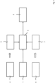
- Fig. 1 shows a schematic representation of functional components for controlling an unmanned aircraft when it is moving along a three-dimensional flight path, in particular functional components for repeatedly providing (current) spatial position data for the unmanned aircraft.
- a first positioning system 1 is provided, which is a satellite navigation system, for example a GPS system.
- the first position determination system 1 is set up to continuously determine first position data for determining a (current) spatial position of the unmanned aircraft. Satellite positioning systems are known as such in various embodiments and provide position data in an associated coordinate system.
- the unmanned aircraft also has a second position determination system 2, which is an image-based position determination system which is set up to determine second position data for the unmanned aircraft from image recordings for the surroundings of the unmanned aircraft.
- a second position determination system 2 which is an image-based position determination system which is set up to determine second position data for the unmanned aircraft from image recordings for the surroundings of the unmanned aircraft.
- an image analysis 3 based on artificial intelligence is provided.
- the first position determination system 1 supplies first position data and the second position determination system 2 supplies second position data.
- the first and second position data are compared or checked according to at least a first test specification.
- the first test specification specifies a predetermined distance between the first position data and the second position data.
- the plausibility check can be carried out in different ways depending on the criticality of the application, in particular according to the principles of secure systems.
- the multi-channel principle the first position data from the first position determination system 1 and the second position data from the second position determination system 2 are checked against each other and, if necessary, by means of optimization, for example average calculation from the first and second position data, into two output signals or a safe signal (position data). processed.
- one path i.e. the first positioning system 1 or the second positioning system 2
- the Doer is switched off and forces a different state of the entire system.
- the checker only forwards validated signals.
- the first position data determines the (current) spatial position of the unmanned aircraft, i.e. the position data that was determined with the satellite navigation system (first position determination system 1), which is assigned to the unmanned aircraft as a master system.
- the unmanned aircraft is then controlled using a control device 5 based on or starting from the spatial position, i.e. in particular based on the first position data.
- the first and second position data in the plausibility check 4 do not satisfy the at least first test specification, provision can be made to include at least a second test specification in the plausibility check 4, the second test specification, for example, having a larger (tolerable) distance in comparison to the first test specification between the first and second position data. If the first and second position data satisfy the second test specification (but not the first test specification), then in one example it is provided that the spatial position of the unmanned aircraft is set equal to the second position data and that the unmanned aircraft then moves based on this or based on this to steer along the three-dimensional flight path.
- the redundant and independent determination of the first and second position data by means of the first and second position determination systems 1, 2, in particular free from a fusion of measurement data and / or specific position data, enables the position data determined by means of the master system to be secured in such a way that it is in As part of the plausibility check 4 can be checked or compared based on the second position data.
- an emergency measure can also be provided if the first and second position data alone do not meet the first test specification.
- provision can be made to execute an error checking specification for the first and second position data if these do not satisfy either the first or the second checking specification.
- the error checking specification may specify an error limit for a distance between the first and second position data.
- an emergency measure can only be provided if it has also been determined that the first and the second position data meet the error checking specification, i.e. show a (incorrect) minimum distance from one another.
- a third position determination system 6 is optionally provided, which is a lidar position determination system which is set up to determine position data from three-dimensional optical measurements of the surroundings of the unmanned aircraft (using an artificial intelligence-based measurement data analysis). regardless of the position data determination in the first and second position determination systems 1, 2.
- the second and third position determination systems 2, 6 can each be used in combination with the first position determination system 1 when controlling the unmanned aircraft. It can also be provided, in addition to the first and second position data, to determine third position data with the third position determination system 6 by means of a measurement data analysis 7 redundantly and independently of the other position determinations. In this way, a further security level can be implemented, in particular in order to check the position data provided by the master system additionally and independently of the comparison between the first and the second position data.
- the first position data provided by the master system i.e. in the exemplary embodiment shown by the first position determination system 1 are only used for the (current) spatial position and thus for the control of the unmanned aircraft if the plausibility check 4 was successful, i.e. a test specification with regard to the second and / or the third position data is fulfilled in relation to the first position data.
- position data are determined independently and in a redundant manner with the help of the position determination systems in order to then check the position data of the master system for plausibility.
- the second or third position determination system 2, 6 can be assigned to the unmanned aircraft as the master system.
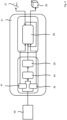
- Fig. 2 and 3 show schematic representations relating to the determination of the first and second position data using artificial intelligence based on the image recordings of the environment (image-based positioning system) or the three-dimensional optical measurements (lidar positioning system).
- Fig. 2 20 images are taken of the surroundings of the unmanned aircraft using one or more cameras.
- a tracking mapping module 21 which is implemented in terms of hardware and software, two temporally successive image recordings 22, 23 are made available to a neural network 24 as input.
- the neural network 24 receives, for example, two three-dimensional digital image matrices (RGB) with the resolution of the camera(s) 20.
- the neural network 24 determines an optical flow 25, i.e. a pixel-based registration of the two image recordings 22, 23, which is expressed as a vector field (pixel displacement per pixel) with a grid size that reflects the image matrix.
- the optical flow 25 serves as input for another neural network 26, which carries out pose estimation.
- the two image recordings 22, 23 as well as the results of the previous pose estimation from the further neural network 26 from the previous time step (iterative) also serve as input for the further neural network 26.
- the further neural network 26 receives the following input variables: two three-dimensional image matrices (image recordings 22, 23, RGB images); pose from previous time step; a one-dimensional image matrix (depth from previous time step); a two-dimensional image matrix (optical flow 25) that estimates depth per pixel; as well as the position as a six-dimensional vector.
- the output position data 27 and disparity or depth data 28 are (optionally) fed to a local and a global bundle adjustment 29, 30 (cf. Fig. 4 below).
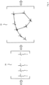
- Fig. 3 shows a schematic representation for position determination using artificial intelligence comparable to that in connection with Fig. 2 described procedure, whereby with the help of a lidar sensor system 40 three-dimensional optical measurement data are recorded, which are then evaluated to determine the position of the unmanned aircraft.
- Fig. 3 the same reference numbers as in Fig. 2 used.
- Successive measurement data 41, 42 are transmitted to the neural network 24 to determine the optical flow 25.
- the successive measurement data 41, 42 here contain a grid of lidar measurement points, which, in comparison to camera image data, assume two values per pixel (depth and intensity), whereby the pixel coordinate represents the grid point in a lidar measurement world.
- Fig. 4 shows a schematic representation regarding the local and global bundle adjustment 29, 30 using the position data 27 and the disparity data 28 (cf. Fig. 2 and 3 ).
- the various position data are optimized using the bundle adjustment 29, 30.
- the individual visual beams of the measurements become the position values optimized across multiple measurements.
- Methods and processes for local and/or global bundle adjustment are known as such in various embodiments (cf. for example Agarwal et al., Bundle adjustment in the large. In Computer Vision - ECCV 2010, 11th European Conference on Computer Vision, p. 29-42, 2010 ).
Landscapes
- Engineering & Computer Science (AREA)
- Physics & Mathematics (AREA)
- General Physics & Mathematics (AREA)
- Aviation & Aerospace Engineering (AREA)
- Radar, Positioning & Navigation (AREA)
- Remote Sensing (AREA)
- Automation & Control Theory (AREA)
- Computer Vision & Pattern Recognition (AREA)
- Theoretical Computer Science (AREA)
- Position Fixing By Use Of Radio Waves (AREA)
- Navigation (AREA)
Applications Claiming Priority (1)
| Application Number | Priority Date | Filing Date | Title |
|---|---|---|---|
| DE102022106110.8A DE102022106110A1 (de) | 2022-03-16 | 2022-03-16 | Verfahren zum sicheren Bestimmen eines Flugpfads eines unbemannten Fluggeräts und unbemanntes Fluggerät |
Publications (2)
| Publication Number | Publication Date |
|---|---|
| EP4246268A1 true EP4246268A1 (fr) | 2023-09-20 |
| EP4246268B1 EP4246268B1 (fr) | 2024-07-24 |
Family
ID=85703951
Family Applications (1)
| Application Number | Title | Priority Date | Filing Date |
|---|---|---|---|
| EP23162077.4A Active EP4246268B1 (fr) | 2022-03-16 | 2023-03-15 | Procédé de détermination sécurisée d'un trajet de vol d'un véhicule aérien sans pilote et véhicule aérien sans pilote |
Country Status (3)
| Country | Link |
|---|---|
| US (1) | US12451019B2 (fr) |
| EP (1) | EP4246268B1 (fr) |
| DE (1) | DE102022106110A1 (fr) |
Citations (5)
| Publication number | Priority date | Publication date | Assignee | Title |
|---|---|---|---|---|
| US20160299231A1 (en) * | 2013-11-11 | 2016-10-13 | Airbus Defence Ang Space Gmbh | Aircraft navigation system and method of navigating an aircraft |
| US20180157220A1 (en) * | 2015-09-16 | 2018-06-07 | SZ DJI Technology Co., Ltd. | Method and apparatus for operating mobile platform |
| US20190340197A1 (en) | 2016-11-30 | 2019-11-07 | Optim Corporation | System and method for controlling camera and program |
| WO2020006709A1 (fr) | 2018-07-04 | 2020-01-09 | 上海峰飞航空科技有限公司 | Système de positionnement visuel, véhicule aérien sans pilote et procédé d'auto-détection de position de véhicule aérien sans pilote |
| US20210247764A1 (en) | 2014-09-05 | 2021-08-12 | SZ DJI Technology Co., Ltd. | Multi-sensor environmental mapping |
Family Cites Families (7)
| Publication number | Priority date | Publication date | Assignee | Title |
|---|---|---|---|---|
| EP1762822A4 (fr) * | 2004-06-29 | 2011-06-29 | Sony Corp | Dispositif et methode de traitement d'information, programme, et systeme de traitement d'information |
| US11435482B2 (en) * | 2014-06-18 | 2022-09-06 | Continental Teves Ag & Co. Ohg | Method for verifying the plausibility of GNSS position signals |
| US11164149B1 (en) * | 2016-08-31 | 2021-11-02 | Corvus Robotics, Inc. | Method and system for warehouse inventory management using drones |
| KR102463176B1 (ko) * | 2017-10-16 | 2022-11-04 | 삼성전자주식회사 | 위치 추정 장치 및 방법 |
| JP7249919B2 (ja) * | 2019-09-17 | 2023-03-31 | 株式会社東芝 | 推定装置、推定方法及びプログラム |
| CN110646825B (zh) * | 2019-10-22 | 2022-01-25 | 北京国家新能源汽车技术创新中心有限公司 | 定位方法、定位系统及汽车 |
| DE102021207769A1 (de) * | 2021-07-21 | 2023-01-26 | Robert Bosch Gesellschaft mit beschränkter Haftung | Verfahren zum Generieren einer Merkmalsbasierten Lokalisierungskarte für eine GNSS- und/oder Merkmalsbasierte Lokalisierung |
-
2022
- 2022-03-16 DE DE102022106110.8A patent/DE102022106110A1/de active Pending
-
2023
- 2023-03-13 US US18/120,545 patent/US12451019B2/en active Active
- 2023-03-15 EP EP23162077.4A patent/EP4246268B1/fr active Active
Patent Citations (5)
| Publication number | Priority date | Publication date | Assignee | Title |
|---|---|---|---|---|
| US20160299231A1 (en) * | 2013-11-11 | 2016-10-13 | Airbus Defence Ang Space Gmbh | Aircraft navigation system and method of navigating an aircraft |
| US20210247764A1 (en) | 2014-09-05 | 2021-08-12 | SZ DJI Technology Co., Ltd. | Multi-sensor environmental mapping |
| US20180157220A1 (en) * | 2015-09-16 | 2018-06-07 | SZ DJI Technology Co., Ltd. | Method and apparatus for operating mobile platform |
| US20190340197A1 (en) | 2016-11-30 | 2019-11-07 | Optim Corporation | System and method for controlling camera and program |
| WO2020006709A1 (fr) | 2018-07-04 | 2020-01-09 | 上海峰飞航空科技有限公司 | Système de positionnement visuel, véhicule aérien sans pilote et procédé d'auto-détection de position de véhicule aérien sans pilote |
Non-Patent Citations (1)
| Title |
|---|
| AGARWAL ET AL.: "Computer Vision - ECCV 2010", 2010, EUROPEAN CONFERENCE ON COMPUTER VISION, article "Bundle adjustment in the large", pages: 29 - 42 |
Also Published As
| Publication number | Publication date |
|---|---|
| US12451019B2 (en) | 2025-10-21 |
| EP4246268B1 (fr) | 2024-07-24 |
| US20230298474A1 (en) | 2023-09-21 |
| DE102022106110A1 (de) | 2023-09-21 |
Similar Documents
| Publication | Publication Date | Title |
|---|---|---|
| DE102016220075A1 (de) | Kraftfahrzeug und Verfahren zur 360°-Umfelderfassung | |
| WO2015173092A1 (fr) | Procédé et dispositif d'étalonnage d'un système de caméra de véhicule automobile | |
| EP2562681B1 (fr) | Procédé de suivi d'objet pour un système d'assistance du conducteur à caméra | |
| DE102012223481A1 (de) | Vorrichtung und Verfahren zum Verfolgen der Position eines peripheren Fahrzeugs | |
| DE102019207448A1 (de) | Simultane Lokalisierung und Kartenerstellung in 2D unter Verwendung eines 3D-Scanners | |
| DE19950247A1 (de) | Regelungsanordnung und Regelungsverfahren für Sstelliten | |
| EP4102486B1 (fr) | Procédé de commande d'un mouvement de vol d'un aéronef, ainsi qu'aéronef | |
| EP2381207B1 (fr) | Mesure de cible 3D et orientation de cible à partir de données IR | |
| DE112020000909T5 (de) | Objektpositionsdetektionsvorrichtung, fahrsteuersystem und fahrsteuerverfahren | |
| DE102019107443A1 (de) | Verfahren und Vorrichtung zum Betrieb eines Roboters mit verbesserter Objektdetektion | |
| DE102011016521A1 (de) | Verfahren zur Flugführung eines Flugzeugs zu einem vorgegebenen Zielobjekt und Flugführungssystem | |
| EP4505211A1 (fr) | Procédé de prédiction de trajectoires d'objets | |
| EP3663881B1 (fr) | Procédé de commande d'un véhicule autonome en fonction des vecteurs de mouvement estimés | |
| DE102018123393A1 (de) | Erkennung von Parkflächen | |
| WO2022218795A1 (fr) | Procédé d'étalonnage d'informations de capteur d'un véhicule et système d'aide à la conduite | |
| DE102021204363A1 (de) | Verfahren zur Kalibrierung eines Sensors mittels eines Fortbewegungsmittels | |
| EP3904827B1 (fr) | Planification dynamique d'itinéraire d'une vérification d'infrastructures d'une voie à l'aide de drones | |
| EP4246268B1 (fr) | Procédé de détermination sécurisée d'un trajet de vol d'un véhicule aérien sans pilote et véhicule aérien sans pilote | |
| EP4145238B1 (fr) | Procédé de commande d'un véhicule aérien sans pilote pour un vol d'inspection servant à inspecter un objet et véhicule aérien d'inspection sans pilote | |
| EP4148386B1 (fr) | Détermination d'une position initiale absolue d'un véhicule | |
| DE102021113111B4 (de) | Verfahren zur Kalibrierung von Sensorinformationen eines Fahrzeugs sowie Fahrassistenzsystem | |
| DE102019127322A1 (de) | Verfahren zur Erfassung von Objekten in einer Fahrzeugumgebung, Vorrichtung zur Datenverarbeitung, Computerprogrammprodukt und computerlesbarer Datenträger | |
| WO2023012096A1 (fr) | Procédé et dispositif de génération de carte pour un véhicule permettant de produire une carte haute résolution d'une surface de sol dans un environnement de véhicule | |
| DE102018217219B4 (de) | Verfahren zum Ermitteln einer dreidimensionalen Position eines Objekts | |
| DE102023002473B3 (de) | Verfahren zur Erstellung eines Datensatzes mit Ground-Truth-Labeln |
Legal Events
| Date | Code | Title | Description |
|---|---|---|---|
| PUAI | Public reference made under article 153(3) epc to a published international application that has entered the european phase |
Free format text: ORIGINAL CODE: 0009012 |
|
| STAA | Information on the status of an ep patent application or granted ep patent |
Free format text: STATUS: THE APPLICATION HAS BEEN PUBLISHED |
|
| AK | Designated contracting states |
Kind code of ref document: A1 Designated state(s): AL AT BE BG CH CY CZ DE DK EE ES FI FR GB GR HR HU IE IS IT LI LT LU LV MC ME MK MT NL NO PL PT RO RS SE SI SK SM TR |
|
| STAA | Information on the status of an ep patent application or granted ep patent |
Free format text: STATUS: REQUEST FOR EXAMINATION WAS MADE |
|
| 17P | Request for examination filed |
Effective date: 20240111 |
|
| RBV | Designated contracting states (corrected) |
Designated state(s): AL AT BE BG CH CY CZ DE DK EE ES FI FR GB GR HR HU IE IS IT LI LT LU LV MC ME MK MT NL NO PL PT RO RS SE SI SK SM TR |
|
| GRAP | Despatch of communication of intention to grant a patent |
Free format text: ORIGINAL CODE: EPIDOSNIGR1 |
|
| STAA | Information on the status of an ep patent application or granted ep patent |
Free format text: STATUS: GRANT OF PATENT IS INTENDED |
|
| INTG | Intention to grant announced |
Effective date: 20240223 |
|
| RIC1 | Information provided on ipc code assigned before grant |
Ipc: G01C 21/20 20060101ALI20240209BHEP Ipc: G05D 1/00 20060101AFI20240209BHEP |
|
| INTG | Intention to grant announced |
Effective date: 20240223 |
|
| GRAS | Grant fee paid |
Free format text: ORIGINAL CODE: EPIDOSNIGR3 |
|
| GRAA | (expected) grant |
Free format text: ORIGINAL CODE: 0009210 |
|
| STAA | Information on the status of an ep patent application or granted ep patent |
Free format text: STATUS: THE PATENT HAS BEEN GRANTED |
|
| AK | Designated contracting states |
Kind code of ref document: B1 Designated state(s): AL AT BE BG CH CY CZ DE DK EE ES FI FR GB GR HR HU IE IS IT LI LT LU LV MC ME MK MT NL NO PL PT RO RS SE SI SK SM TR |
|
| REG | Reference to a national code |
Ref country code: GB Ref legal event code: FG4D Free format text: NOT ENGLISH |
|
| REG | Reference to a national code |
Ref country code: CH Ref legal event code: EP |
|
| REG | Reference to a national code |
Ref country code: IE Ref legal event code: FG4D Free format text: LANGUAGE OF EP DOCUMENT: GERMAN Ref country code: DE Ref legal event code: R096 Ref document number: 502023000082 Country of ref document: DE |
|
| REG | Reference to a national code |
Ref country code: LT Ref legal event code: MG9D |
|
| REG | Reference to a national code |
Ref country code: NL Ref legal event code: MP Effective date: 20240724 |
|
| PG25 | Lapsed in a contracting state [announced via postgrant information from national office to epo] |
Ref country code: PT Free format text: LAPSE BECAUSE OF FAILURE TO SUBMIT A TRANSLATION OF THE DESCRIPTION OR TO PAY THE FEE WITHIN THE PRESCRIBED TIME-LIMIT Effective date: 20241125 |
|
| PG25 | Lapsed in a contracting state [announced via postgrant information from national office to epo] |
Ref country code: NL Free format text: LAPSE BECAUSE OF FAILURE TO SUBMIT A TRANSLATION OF THE DESCRIPTION OR TO PAY THE FEE WITHIN THE PRESCRIBED TIME-LIMIT Effective date: 20240724 |
|
| PG25 | Lapsed in a contracting state [announced via postgrant information from national office to epo] |
Ref country code: PT Free format text: LAPSE BECAUSE OF FAILURE TO SUBMIT A TRANSLATION OF THE DESCRIPTION OR TO PAY THE FEE WITHIN THE PRESCRIBED TIME-LIMIT Effective date: 20241125 Ref country code: NL Free format text: LAPSE BECAUSE OF FAILURE TO SUBMIT A TRANSLATION OF THE DESCRIPTION OR TO PAY THE FEE WITHIN THE PRESCRIBED TIME-LIMIT Effective date: 20240724 |
|
| PG25 | Lapsed in a contracting state [announced via postgrant information from national office to epo] |
Ref country code: NO Free format text: LAPSE BECAUSE OF FAILURE TO SUBMIT A TRANSLATION OF THE DESCRIPTION OR TO PAY THE FEE WITHIN THE PRESCRIBED TIME-LIMIT Effective date: 20241024 |
|
| PG25 | Lapsed in a contracting state [announced via postgrant information from national office to epo] |
Ref country code: FI Free format text: LAPSE BECAUSE OF FAILURE TO SUBMIT A TRANSLATION OF THE DESCRIPTION OR TO PAY THE FEE WITHIN THE PRESCRIBED TIME-LIMIT Effective date: 20240724 Ref country code: GR Free format text: LAPSE BECAUSE OF FAILURE TO SUBMIT A TRANSLATION OF THE DESCRIPTION OR TO PAY THE FEE WITHIN THE PRESCRIBED TIME-LIMIT Effective date: 20241025 Ref country code: PL Free format text: LAPSE BECAUSE OF FAILURE TO SUBMIT A TRANSLATION OF THE DESCRIPTION OR TO PAY THE FEE WITHIN THE PRESCRIBED TIME-LIMIT Effective date: 20240724 |
|
| PG25 | Lapsed in a contracting state [announced via postgrant information from national office to epo] |
Ref country code: BG Free format text: LAPSE BECAUSE OF FAILURE TO SUBMIT A TRANSLATION OF THE DESCRIPTION OR TO PAY THE FEE WITHIN THE PRESCRIBED TIME-LIMIT Effective date: 20240724 |
|
| PG25 | Lapsed in a contracting state [announced via postgrant information from national office to epo] |
Ref country code: LV Free format text: LAPSE BECAUSE OF FAILURE TO SUBMIT A TRANSLATION OF THE DESCRIPTION OR TO PAY THE FEE WITHIN THE PRESCRIBED TIME-LIMIT Effective date: 20240724 |
|
| PG25 | Lapsed in a contracting state [announced via postgrant information from national office to epo] |
Ref country code: IS Free format text: LAPSE BECAUSE OF FAILURE TO SUBMIT A TRANSLATION OF THE DESCRIPTION OR TO PAY THE FEE WITHIN THE PRESCRIBED TIME-LIMIT Effective date: 20241124 |
|
| PG25 | Lapsed in a contracting state [announced via postgrant information from national office to epo] |
Ref country code: HR Free format text: LAPSE BECAUSE OF FAILURE TO SUBMIT A TRANSLATION OF THE DESCRIPTION OR TO PAY THE FEE WITHIN THE PRESCRIBED TIME-LIMIT Effective date: 20240724 |
|
| PG25 | Lapsed in a contracting state [announced via postgrant information from national office to epo] |
Ref country code: ES Free format text: LAPSE BECAUSE OF FAILURE TO SUBMIT A TRANSLATION OF THE DESCRIPTION OR TO PAY THE FEE WITHIN THE PRESCRIBED TIME-LIMIT Effective date: 20240724 Ref country code: RS Free format text: LAPSE BECAUSE OF FAILURE TO SUBMIT A TRANSLATION OF THE DESCRIPTION OR TO PAY THE FEE WITHIN THE PRESCRIBED TIME-LIMIT Effective date: 20241024 |
|
| PG25 | Lapsed in a contracting state [announced via postgrant information from national office to epo] |
Ref country code: RS Free format text: LAPSE BECAUSE OF FAILURE TO SUBMIT A TRANSLATION OF THE DESCRIPTION OR TO PAY THE FEE WITHIN THE PRESCRIBED TIME-LIMIT Effective date: 20241024 Ref country code: PL Free format text: LAPSE BECAUSE OF FAILURE TO SUBMIT A TRANSLATION OF THE DESCRIPTION OR TO PAY THE FEE WITHIN THE PRESCRIBED TIME-LIMIT Effective date: 20240724 Ref country code: NO Free format text: LAPSE BECAUSE OF FAILURE TO SUBMIT A TRANSLATION OF THE DESCRIPTION OR TO PAY THE FEE WITHIN THE PRESCRIBED TIME-LIMIT Effective date: 20241024 Ref country code: LV Free format text: LAPSE BECAUSE OF FAILURE TO SUBMIT A TRANSLATION OF THE DESCRIPTION OR TO PAY THE FEE WITHIN THE PRESCRIBED TIME-LIMIT Effective date: 20240724 Ref country code: IS Free format text: LAPSE BECAUSE OF FAILURE TO SUBMIT A TRANSLATION OF THE DESCRIPTION OR TO PAY THE FEE WITHIN THE PRESCRIBED TIME-LIMIT Effective date: 20241124 Ref country code: HR Free format text: LAPSE BECAUSE OF FAILURE TO SUBMIT A TRANSLATION OF THE DESCRIPTION OR TO PAY THE FEE WITHIN THE PRESCRIBED TIME-LIMIT Effective date: 20240724 Ref country code: GR Free format text: LAPSE BECAUSE OF FAILURE TO SUBMIT A TRANSLATION OF THE DESCRIPTION OR TO PAY THE FEE WITHIN THE PRESCRIBED TIME-LIMIT Effective date: 20241025 Ref country code: FI Free format text: LAPSE BECAUSE OF FAILURE TO SUBMIT A TRANSLATION OF THE DESCRIPTION OR TO PAY THE FEE WITHIN THE PRESCRIBED TIME-LIMIT Effective date: 20240724 Ref country code: ES Free format text: LAPSE BECAUSE OF FAILURE TO SUBMIT A TRANSLATION OF THE DESCRIPTION OR TO PAY THE FEE WITHIN THE PRESCRIBED TIME-LIMIT Effective date: 20240724 Ref country code: BG Free format text: LAPSE BECAUSE OF FAILURE TO SUBMIT A TRANSLATION OF THE DESCRIPTION OR TO PAY THE FEE WITHIN THE PRESCRIBED TIME-LIMIT Effective date: 20240724 |
|
| PG25 | Lapsed in a contracting state [announced via postgrant information from national office to epo] |
Ref country code: SM Free format text: LAPSE BECAUSE OF FAILURE TO SUBMIT A TRANSLATION OF THE DESCRIPTION OR TO PAY THE FEE WITHIN THE PRESCRIBED TIME-LIMIT Effective date: 20240724 Ref country code: RO Free format text: LAPSE BECAUSE OF FAILURE TO SUBMIT A TRANSLATION OF THE DESCRIPTION OR TO PAY THE FEE WITHIN THE PRESCRIBED TIME-LIMIT Effective date: 20240724 Ref country code: DK Free format text: LAPSE BECAUSE OF FAILURE TO SUBMIT A TRANSLATION OF THE DESCRIPTION OR TO PAY THE FEE WITHIN THE PRESCRIBED TIME-LIMIT Effective date: 20240724 |
|
| PG25 | Lapsed in a contracting state [announced via postgrant information from national office to epo] |
Ref country code: EE Free format text: LAPSE BECAUSE OF FAILURE TO SUBMIT A TRANSLATION OF THE DESCRIPTION OR TO PAY THE FEE WITHIN THE PRESCRIBED TIME-LIMIT Effective date: 20240724 |
|
| PG25 | Lapsed in a contracting state [announced via postgrant information from national office to epo] |
Ref country code: CZ Free format text: LAPSE BECAUSE OF FAILURE TO SUBMIT A TRANSLATION OF THE DESCRIPTION OR TO PAY THE FEE WITHIN THE PRESCRIBED TIME-LIMIT Effective date: 20240724 |
|
| REG | Reference to a national code |
Ref country code: DE Ref legal event code: R097 Ref document number: 502023000082 Country of ref document: DE |
|
| PG25 | Lapsed in a contracting state [announced via postgrant information from national office to epo] |
Ref country code: IT Free format text: LAPSE BECAUSE OF FAILURE TO SUBMIT A TRANSLATION OF THE DESCRIPTION OR TO PAY THE FEE WITHIN THE PRESCRIBED TIME-LIMIT Effective date: 20240724 Ref country code: SK Free format text: LAPSE BECAUSE OF FAILURE TO SUBMIT A TRANSLATION OF THE DESCRIPTION OR TO PAY THE FEE WITHIN THE PRESCRIBED TIME-LIMIT Effective date: 20240724 |
|
| PLBE | No opposition filed within time limit |
Free format text: ORIGINAL CODE: 0009261 |
|
| STAA | Information on the status of an ep patent application or granted ep patent |
Free format text: STATUS: NO OPPOSITION FILED WITHIN TIME LIMIT |
|
| 26N | No opposition filed |
Effective date: 20250425 |
|
| PG25 | Lapsed in a contracting state [announced via postgrant information from national office to epo] |
Ref country code: SE Free format text: LAPSE BECAUSE OF FAILURE TO SUBMIT A TRANSLATION OF THE DESCRIPTION OR TO PAY THE FEE WITHIN THE PRESCRIBED TIME-LIMIT Effective date: 20240724 |
|
| PG25 | Lapsed in a contracting state [announced via postgrant information from national office to epo] |
Ref country code: MC Free format text: LAPSE BECAUSE OF FAILURE TO SUBMIT A TRANSLATION OF THE DESCRIPTION OR TO PAY THE FEE WITHIN THE PRESCRIBED TIME-LIMIT Effective date: 20240724 |
|
| PG25 | Lapsed in a contracting state [announced via postgrant information from national office to epo] |
Ref country code: LU Free format text: LAPSE BECAUSE OF NON-PAYMENT OF DUE FEES Effective date: 20250315 |
|
| REG | Reference to a national code |
Ref country code: BE Ref legal event code: MM Effective date: 20250331 |
|
| PG25 | Lapsed in a contracting state [announced via postgrant information from national office to epo] |
Ref country code: BE Free format text: LAPSE BECAUSE OF NON-PAYMENT OF DUE FEES Effective date: 20250331 |
|
| PG25 | Lapsed in a contracting state [announced via postgrant information from national office to epo] |
Ref country code: IE Free format text: LAPSE BECAUSE OF NON-PAYMENT OF DUE FEES Effective date: 20250315 |
|
| PGFP | Annual fee paid to national office [announced via postgrant information from national office to epo] |
Ref country code: DE Payment date: 20260320 Year of fee payment: 4 |
|
| PGFP | Annual fee paid to national office [announced via postgrant information from national office to epo] |
Ref country code: AT Payment date: 20260301 Year of fee payment: 4 |
|
| PGFP | Annual fee paid to national office [announced via postgrant information from national office to epo] |
Ref country code: FR Payment date: 20260323 Year of fee payment: 4 |