EP4249373A1 - Véhicule aérien, procédé de fonctionnement d'un véhicule aérien et dispositif de commande - Google Patents
Véhicule aérien, procédé de fonctionnement d'un véhicule aérien et dispositif de commande Download PDFInfo
- Publication number
- EP4249373A1 EP4249373A1 EP22164028.7A EP22164028A EP4249373A1 EP 4249373 A1 EP4249373 A1 EP 4249373A1 EP 22164028 A EP22164028 A EP 22164028A EP 4249373 A1 EP4249373 A1 EP 4249373A1
- Authority
- EP
- European Patent Office
- Prior art keywords
- propulsion units
- rotor
- aerial vehicle
- propulsion
- rotational speed
- Prior art date
- Legal status (The legal status is an assumption and is not a legal conclusion. Google has not performed a legal analysis and makes no representation as to the accuracy of the status listed.)
- Pending
Links
Images
Classifications
-
- B—PERFORMING OPERATIONS; TRANSPORTING
- B64—AIRCRAFT; AVIATION; COSMONAUTICS
- B64C—AEROPLANES; HELICOPTERS
- B64C11/00—Propellers, e.g. of ducted type; Features common to propellers and rotors for rotorcraft
- B64C11/46—Arrangements of, or constructional features peculiar to, multiple propellers
-
- B—PERFORMING OPERATIONS; TRANSPORTING
- B64—AIRCRAFT; AVIATION; COSMONAUTICS
- B64C—AEROPLANES; HELICOPTERS
- B64C29/00—Aircraft capable of landing or taking-off vertically, e.g. vertical take-off and landing [VTOL] aircraft
- B64C29/0008—Aircraft capable of landing or taking-off vertically, e.g. vertical take-off and landing [VTOL] aircraft having its flight directional axis horizontal when grounded
- B64C29/0016—Aircraft capable of landing or taking-off vertically, e.g. vertical take-off and landing [VTOL] aircraft having its flight directional axis horizontal when grounded the lift during taking-off being created by free or ducted propellers or by blowers
- B64C29/0033—Aircraft capable of landing or taking-off vertically, e.g. vertical take-off and landing [VTOL] aircraft having its flight directional axis horizontal when grounded the lift during taking-off being created by free or ducted propellers or by blowers the propellers being tiltable relative to the fuselage
-
- B—PERFORMING OPERATIONS; TRANSPORTING
- B64—AIRCRAFT; AVIATION; COSMONAUTICS
- B64D—EQUIPMENT FOR FITTING IN OR TO AIRCRAFT; FLIGHT SUITS; PARACHUTES; ARRANGEMENT OR MOUNTING OF POWER PLANTS OR PROPULSION TRANSMISSIONS IN AIRCRAFT
- B64D27/00—Arrangement or mounting of power plants in aircraft; Aircraft characterised by the type or position of power plants
- B64D27/02—Aircraft characterised by the type or position of power plants
- B64D27/30—Aircraft characterised by electric power plants
- B64D27/31—Aircraft characterised by electric power plants within, or attached to, wings
-
- B—PERFORMING OPERATIONS; TRANSPORTING
- B64—AIRCRAFT; AVIATION; COSMONAUTICS
- B64C—AEROPLANES; HELICOPTERS
- B64C11/00—Propellers, e.g. of ducted type; Features common to propellers and rotors for rotorcraft
- B64C11/16—Blades
-
- B—PERFORMING OPERATIONS; TRANSPORTING
- B64—AIRCRAFT; AVIATION; COSMONAUTICS
- B64C—AEROPLANES; HELICOPTERS
- B64C2220/00—Active noise reduction systems
-
- B—PERFORMING OPERATIONS; TRANSPORTING
- B64—AIRCRAFT; AVIATION; COSMONAUTICS
- B64D—EQUIPMENT FOR FITTING IN OR TO AIRCRAFT; FLIGHT SUITS; PARACHUTES; ARRANGEMENT OR MOUNTING OF POWER PLANTS OR PROPULSION TRANSMISSIONS IN AIRCRAFT
- B64D27/00—Arrangement or mounting of power plants in aircraft; Aircraft characterised by the type or position of power plants
- B64D27/02—Aircraft characterised by the type or position of power plants
- B64D27/30—Aircraft characterised by electric power plants
- B64D27/34—All-electric aircraft
Definitions
- the present invention relates to an aerial vehicle, a method of operating an aerial vehicle, and a controller.
- Noise pollution is a significant aspect taken into consideration in air traffic.
- several strategies have been followed.
- One aspect focuses on reducing the noise pollution of aerial vehicles themselves.
- aerial vehicles comprising a plurality of propulsion units configured to power the aerial vehicle, wherein each of the propulsion units comprises at least one rotor, such as a fan, and the at least one rotor comprises at least component, such as blades, rotating integrally with the rotor, respectively.
- Components such as the fan of the aerial vehicle itself have been developed with the object of reducing noise emission.
- an aerial vehicle comprising: a plurality of propulsion units configured to power the aerial vehicle, wherein each of the propulsion units comprises at least one rotor and the at least one rotor comprises at least one, preferably a number of components rotating integrally with the rotor, respectively.
- the number of components of the rotor of at least two, preferably all, of the propulsion units is different from each other.
- the at least two of the plurality of propulsion units can be configured such that they have at least one respective, in particular, a fundamental, tonal noise frequency different from each other, at least during operation of the aerial vehicle.
- the propulsion units and their rotors are identified as noise relevant components.
- tonal noise frequencies can be scattered.
- the sound pressure level of tonal noise frequencies is not accumulated at one tonal noise frequency but is distributed to at least two tonal noise frequencies, namely, at least the respective tonal noise frequencies, among the at least two propulsion units.
- the expression "respective tonal noise frequency” may refer to the order of the tonal noise frequency. Especially, the fundamental noise frequency may be considered by this term. It may further relate to a tonal noise frequency of the corresponding acoustic source.
- the rotors are dynamic portions and thus may contribute significantly to the noise emission of propulsion units, and thus, of the aerial vehicle.
- rotors may generate tonal noise frequency in accordance with their respective rotational speed. According to the first aspect, these tonal noise frequencies can be reliably scattered.
- the rotors may generate noise due to any of a mechanical, aerodynamic, electric, magnetic interactions, etc., or combinations thereof with the ambient or other portions.
- the number of components of at least one rotor of each of the at least two propulsion units may be different from each other. However, preferably, the number of components of each rotor of each of the at least two propulsion units may be different from each other. In this regard, it is even more preferable that the number of components of each rotor in each propulsion unit is different from each other.
- Integrally rotating components are components rotating with the same rotational speed and torque. They can be mounted to or integrally formed with a rotor main body. Since the tonal noise frequencies may be proportional to the number of components integrally rotating with the rotor, the tonal noise frequencies can be reliably scattered by making the number of integrally rotating components different from each other.
- At least one rotor of the at least two propulsion units has the same function in the at least two propulsion units, respectively, and more preferably, the at least one component has the same function in the rotor, respectively.
- the rotors may interact in many ways with the ambient to generate noise.
- Rotors having the same function will also be referred to as corresponding rotors.
- components having the same function in the respective rotors will be referred to as corresponding components.
- a corresponding rotor is a rotor being present in any of the at least two propulsion units.
- the corresponding rotors may be assigned with the same principal function in each of the at least two propulsion units. In other words, they can be identified by their respective function. Functions may be thrust generation, cooling, driving, transmitting, etc.
- corresponding rotors may be of the same type such as impellers, propellers, compressor stage rotors, etc. Thereby, the same type of acoustic source can be more reliably distributed to several tonal noise frequencies.
- Corresponding components may refer to components which are present in the at least two propulsion units, preferably in each of, the plurality of propulsion units. Thus, it is not necessary to add a component to one propulsion unit which is not present in any other of the at least two propulsion units.
- corresponding components may be characterized by having the same type of interaction with the ambient or other portions.
- Corresponding components may be assigned to the principal function of the corresponding rotors. Further, corresponding components may be components having substantially the same structure.
- the at least one component is arranged along a circumferential direction, and/or extending in a radial direction of a rotation axis of the respective rotor.
- the rotor may be a thrust generating rotor, preferably, a fan, and/or the at least one component may be a blade.
- rotors may disturb the air stream and also may be exposed to different flow situations, and thus may represent a source for significant noise.
- the aerodynamic interactions in the respective rotors may differ from each other such that the tonal noise frequencies may be reliably scattered.
- the thrust generating rotor is configured to generate a thrust force for powering the aerial vehicle and may be a propeller or impeller, for example.
- the rotor may be a rotor of a rotary electric machine, and/or the at least one component may be a pole.
- the electromagnetic interactions in the respective rotary electric machines may differ from each other such that the tonal noise frequencies may be reliably scattered.
- the rotary electric machine is arranged to drive the thrust generating rotor.
- both rotors may rotate integrally and may have the same rotational speed in the respective propulsion unit such that scattering of the tonal noise frequencies can be reliably established.
- the number of components of the rotor of one propulsion unit may not be an integer multiple of the number of components of the rotor of at least one other propulsion unit.
- the number of components of the rotor of each propulsion unit is not an integer multiple of the number of components of the rotor of any other propulsion unit.
- the aerial vehicle may be of a VTOL type wherein the at least two propulsion units are transferable, preferably pivotable, between are take-off-and-landing state and a cruising state.
- this type of aerial vehicle may be used for traveling in populated areas such that the above aspects can be preferably provided.
- the at least two propulsion units are configured such that a sound pressure level of any of the tonal noise frequencies of the at least two propulsion units is lower than a maximum sound pressure level of a tonal noise frequency of a state in which at least one respective tonal noise frequency of the at least two propulsion units is the same, preferably, the sound pressure level of any of the tonal noise frequencies of the at least two propulsion units is equal to or lower than the human ear threshold of recognition of tonal noise.
- the sound pressure level emitted for any tonal noise frequency can be reliably lowered such that the annoyance caused by noise pollution can be decreased. That is, if at least one respective tonal noise frequency in one propulsion unit is equal to the respective tonal noise frequency in at least one other propulsion unit, the sound pressure levels may superimpose to form a maximum at the respective tonal noise frequency which can be reliably prevented from being reached. By lowering the sound pressure level of any tonal noise frequency below the human ear threshold, the burden on human beings can be further reduced.
- the foregoing aspects are preferably provided in a state in which the at least two propulsion units are operated in the same manner, in particular, in terms of a rotational speed.
- control of the aerial vehicle can be simplified.
- a method of operating an aerial vehicle comprising: a plurality of propulsion units configured to power the aerial vehicle, each of the propulsion units comprises at least one rotor and the at least one rotor comprises at least one, preferably a number, of components rotating integrally with the rotor, respectively.
- the method comprises at least the step of: operating at least two, preferably all, of the propulsion units at a different rotational speed, preferably, at least temporarily during a steady flight state of the aerial vehicle.
- the steady flight state of the aerial vehicle may comprise any of a, in particular substantially vertical, ascent or descent, cruise flight, and turning flight. In particular, it may refer to a state in which the aerial vehicle is in an equilibrium state such as flying along or about at least one axis with constant velocity. In particular, the loads applied by the plurality of propulsion units may substantially not cause any momentum around one axis.
- the tonal noise frequencies may be scattered while a steady flight state may be maintained. In this way, the noise emission can be reduced in an easy manner.
- the at least two propulsion units have a corresponding rotor, respectively, as it has been presented above, and the corresponding rotors of the at least two propulsion units are operated with a different rotational speed.
- the corresponding rotors have the same structure.
- the at least two propulsion units are operated in a different manner at least temporarily during a transition of the propulsion units between the take-off-and-landing state and a cruising state.
- At least one, preferably several ones, of the plurality of propulsion units is/are operated above a predetermined rotational speed, and at least one other, preferably several others, of the plurality of propulsion units is/are operated below the predetermined rotational speed.
- the rotational speed and, thus, the respective tonal noise frequencies which may be proportional to the rotational speed can be reliably scattered.
- the at least one and the at least other propulsion unit are operated with the same absolute difference to the predetermined rotational speed.
- the rotational speed in average can be made substantially equal to the predetermined rotational speed.
- the number of propulsion units operated above the predetermined rotational speed is the same as the number of propulsion units operated below the predetermined rotational speed.
- the steady flight state can be more reliably maintained and the impact of the at least two propulsion units operated differently on the aerial vehicle can be reduced.
- the predetermined speed may be an overall average rotational speed of the propulsion units and/or a design rotational speed of the propulsion units.
- the design rotational speed may be a rotational speed required if the propulsion units are operated the same way in order to establish cruising.
- the at least two propulsion units have the same structure.
- the design as well as the control of the aerial vehicle can be simplified. Also, maintenance can be improved. Further, the scattering of tonal noise frequencies can be more reliably performed since scattering of tonal noise frequencies can be easily achieved by changing the rotational speed among the at least two propulsion units.
- the operation of the at least two propulsion units at the different rotational speeds is established depending on a position of the aerial vehicle, in particular, a position with respect to a predetermined area on a flight trajectory.
- the at least two propulsion units may be operated at different rotational speeds at specific locations on the flight trajectory. If the aerial vehicle is located within the predetermined area the above control may be performed, while if it is located outside of the predetermined area, the at least two propulsion units may be controlled at the same rotational speed. Thus, outside of predetermined areas, flight efficiency can be enhanced while in the predetermined area the annoyance resulting from noise can be reduced.
- Still another aspect provides a controller configured to carry out the method of any of aforementioned aspects, when coupled to the at least two propulsion units.
- an aerial vehicle which comprises: a plurality of propulsion units configured to power the aerial vehicle, and the aforementioned controller.
- the aerial vehicle can be reliably controlled to reduce noise emissions in view of the above aspects.
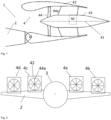
- Fig. 1 shows a side view of a part of an aerial vehicle 1.
- Fig. 2 shows a front view of the aerial vehicle 1.
- the aerial vehicle 1 comprises a principal lift generation body 2 which may be an airfoil, for example.
- the airfoil 2 is attached to a fuselage 3.
- the airfoil extends substantially along a left-right (widthwise axis) direction of the aerial vehicle 1 to traverse the fuselage 3 which extends substantially along the front rear direction (longitudinal axis).
- the airfoil 2 comprises an aerodynamic profile in order to generate lift. The chord of the profile may be inclined with respect to the longitudinal axis.
- the aerial vehicle 1 further comprises a plurality of propulsion units 4.
- Each of the plurality of propulsion units 4 is attached to the airfoil 2 at a rear portion, in particular, at a rear end, thereof.
- the propulsion units 4 are attached to a bracket provided at the rear portion of the airfoil 2, respectively.
- the propulsion units 4 are each attached to be pivotally about the widthwise axis of the aerial vehicle 1 with respect to the airfoil 2.
- the aerial vehicle 1 is of a VTOL (vertical-take-off-and-landing) type.
- the propulsion unit 4 is pivotable between a cruising state, in which a propulsion axis 41, shown in Fig. 1 , is substantially aligned with the longitudinal axis or the chord of the airfoil, and a take-off-and-landing state, in which the propulsion axis 41, is aligned with an up-down direction (gravity axis) of the aerial vehicle 1.
- the number of propulsion units 4 arranged to the left and right side of the longitudinal axis is the same, respectively.
- Fig. 2 shows two propulsion units 4a and 4b on the left side, and two propulsion units 4c and 4d on the right side of the longitudinal axis.
- the propulsion units 4a and 4c are located closer to the longitudinal axis than the propulsion units 4b and 4d, respectively.
- the propulsion units 4a and 4c as well as the propulsion units 4b and 4d have the same distance to the longitudinal axis.
- Each propulsion unit 4 has substantially the same structure.
- Each propulsion unit comprises a shroud 42.
- the shroud 42 has an aerodynamic peripheral surface 42 which has a profile shape. In this manner, each propulsion unit 4 can function as secondary lift generation body.
- each propulsion unit 4 is further electrically driven.
- each propulsion unit 4 comprises a rotary electric machine M arranged inside of an inner case 43.
- the rotary electric machine M is, for example, an electric motor.
- the rotary electric machine M may be an electric asynchronous motor, but may be also a synchronous motor.
- the rotary electric machine may be driven with rotary current such as three phase current, alternate current or direct current.
- the rotary electric machine comprises a stator and a rotor.
- the rotor may have two winding portions provided with direct current to form one pole pair.
- the stator may comprise a permanent magnet.
- the rotary electric machine M is arranged to drive a thrust generating rotor 44 which is embodied as a fan.
- the rotor of the rotary electric machine M is coupled to the thrust generating rotor 44 to transmit torque to the thrust generating rotor 44.
- each propulsion unit 4 is of a ducted fan type wherein the fan is arranged on the inside of the shroud 42.
- a transmission preferably comprising a plurality of rotors such as gears, may be interposed between the rotor of the rotary electric machine M and the thrust generating rotor 44.
- the thrust generating rotor 44 comprises a plurality of blades 44a and a hub.
- the blades 44a are arranged along a circumferential direction around the propulsion axis 41 and extend in the radial direction of the thrust axis 41.
- the blades 44a are preferably equally spaced apart from each other along the circumferential direction.
- the blades 44a are mounted to the hub to rotate integrally with the hub.
- the power provided by the rotary electric machine M is transmitted to the hub which integrally rotates with the blades 44a.
- the blades 44a are arranged to energize, in particular, accelerate, the air stream to provide a thrust force directed substantially along the propulsion axis 41.
- the number of blades 44a rotating integrally with the hub differs among the propulsion units 4a, 4b, 4c, and 4d.
- Each propulsion unit has a number of blades 44a different from each other.
- the blades 44a preferably have the same shape and structure.
- the number of blades 44a being different may be the only structural difference among the plurality of propulsion units 4a, 4b, 4c, and 4d.
- the propulsion units may be designed to generate substantially the same thrust when operated at the same rotational speed.
- Each propulsion unit of the plurality of propulsion units 4a, 4b, 4c, and 4d has a different number of blades 44a with respect to the number of blades 44a in any other propulsion unit.
- n is the number of blades 44a rotating integrally with the respective hub and any integer multiple therefrom.
- the tonal noise frequency f t is proportional to the number of blades 44a as an example of integrally rotating components and corresponding components which are present in every propulsion unit 4.
- the respective tonal noise frequency f t emitted from the respective thrust generating rotor 44 of each propulsion unit 4a, 4b, 4c, and 4d is different.
- at least the respective fundamental tonal noise frequency of a corresponding acoustic source of each propulsion unit is different, wherein the corresponding acoustic source is the aerodynamic (fluid mechanic) interaction of the blades 44a with the air stream. Accordingly, the sound pressure level does not accumulate at a specific tonal noise frequency.
- annoyance caused by noise can be significantly reduced by a difference in the structure of the propulsion units 4a, 4b, 4c, and 4d.
- each thrust generating rotor 44 is not an integer multiple of the number of corresponding components in any other corresponding thrust generating rotor 44.
- an accumulation at any tonal noise frequency f t can be avoided at least if the propulsion units are operated at the same rotational speed.
- each propulsion unit in particular, each rotor, has a number of corresponding components, when divided in prime numbers, having at least one prime number different from the respective prime numbers of the number of corresponding components of any other propulsion unit.
- propulsion unit 4a may have 8 blades 44a (only primary number 2), while propulsion unit 4b may have 14 blades 44a (primary numbers 2 and 7), while propulsion unit 4c may have 10 blades 44a (primary numbers 2 and 5), and propulsion unit 4d may have 12 blades 44a (primary numbers 2 and 3).
- the least common multiple can be made large. In other words, it is preferable, that with the smallest number of corresponding components among the propulsion units given, the least common multiple is maximized.
- the different number of blades 44a is not shown in Fig. 2 .
- the propulsion units may be arranged such that on both sides the same average of the number of components is achieved.
- propulsion units 4a and 4c have the largest difference in the number of corresponding components among the plurality of propulsion units.
- the propulsion units closest to the fuselage 3 may have the maximum least common multiple among any pair of two propulsion units on the left and right side, respectively.
- n basic is the smallest number of components (blades in the present case) among the corresponding rotors
- PU is the number of propulsion units.
- the corresponding rotor considered is the thrust generating rotor 44 which represents one corresponding acoustic source for each propulsion unit 4.
- the thrust generating rotor need not be the fan but can be any other rotor in the propulsion unit configured to generate thrust such as a propeller.
- the rotor may be a single compressor or turbine stage in a combustion propulsion unit.
- the principal function of the thrust generating rotor 44 is to generate thrust. As the blades 44a energize the air stream, they are assigned to the principal function of the rotor.
- the corresponding rotor having the different number of components may be the rotor of the rotary electric machine M.
- the different number of components may be represented by a different number of poles in the respective rotary electric machine M of each propulsion unit.
- the number of pole pairs may be different, wherein each pole pair counts as one component.
- the number of poles may be represented by the number of phases provided by the rotary current.
- the poles can be formed by the winding portions which are also arranged along a circumferential direction and extend in the radial direction.
- a corresponding rotor may be a portion of a transmission, for example, between the rotary electric machine M and the thrust generating rotor 44, and may comprise a meshing portion such as a gear or worm shaft, wherein the different number of components may be represented by a different number of meshing components such as teeth to be engaged with an adjacent gear.
- corresponding rotors are preferably of the same type and have substantially the same structure.
- the propulsion units having the different number of components are preferably attached to the same type of attaching object, preferably, the same type of lift generating body.
- they may be attached to the airfoil 2 or a canard being examples of an attaching object.
- they may also be attached to the fuselage 3, for example.
- the aerial vehicle 1 may further comprise at least one controller, for example, an ECU coupled to the propulsion units to control operation of the propulsion units 4a, 4b, 4c, and 4d.
- a controller may be provided for each propulsion unit while a central controller may be coupled to theses controllers of the propulsion units to provide them with signals.
- the controller preferably controls the corresponding rotors to operate at the same rotational speed at least during a steady flight state.
- the propulsion units 4a, 4b, 4c, and 4d may have the same structure, but may be controlled to operate in a different manner.
- the propulsion units may be controlled to operate at a rotational speed different from each other during a steady flight state.
- the propulsion units 4a and 4c having the same distance to the longitudinal axis may be operated at a rotational speed different from each other, and preferably, also different from a rotational speed of the propulsion units 4b and 4d. Accordingly, also the propulsion units 4b and 4d having substantially the same distance to the longitudinal axis may be operated with a different rotational speed.
- the propulsion units 4a, 4b, 4c and 4d may be operated such that two propulsion units, for example, 4a and 4c, being located closest to the fuselage 3 are operated below an overall average rotational speed while the outer propulsion units 4b and 4d are operated above the overall average rotational speed. Thereby, the noise emission towards the fuselage can be reduced.
- the overall rotational speed is one example of a predetermined rotational speed which is preferably a design rotational speed of the respective propulsion units.
- the design rotational speed may be determined based on the thrust requirements during cruising.
- the propulsion units 4a, 4b, 4c, and 4d can be operated such that the thrust to maintain the steady flight state is maintained.
- the propulsion units 4a, 4b, 4c, and 4d are further preferably controlled such that they do not provide a torque, in particular, around at least one of the three principal axes. Thereby, the steady flight state can be reliably maintained.
- the propulsion units may be controlled such that on each side of the longitudinal axis, the same average rotational speed is established. Thereby, substantially the same thrust can be generated on both sides of the longitudinal axis such that the structure can be stressed in a substantially uniform manner.
- At least one pair of propulsion units 4a and 4b may have the same absolute difference regarding the overall average rotational speed. Accordingly, on the other side, the propulsion units 4c and 4d may also be operated to have the same absolute difference with respect to the overall rotational average speed.
- the above control may be performed depending on the location on the flight trajectory.
- the controller may receive navigation data such as GPS data to locate the aerial vehicle 1. If the aerial vehicle is outside of a predetermined area, the propulsion units may all be operated at their design rotational speed. If the aerial vehicle is within the predetermined area, the above control at different rotational speeds can be established.
- the predetermined area may comprise noise sensitive area such as cities and/or environmental protection areas.
- the predetermined area may be determined as an area encompassing the noise sensitive area by a predetermined distance, or only be the noise sensitive area.
- the predetermined area can be stored in a storage of the controller or in an external storage which can communicate with the controller.
- the control is preferably performed over a couple of minutes, preferably more than 10 minutes, during the steady flight state, or over a couple of seconds, preferably more than 5 seconds, during a transition state of the propulsion units between the cruising state and the take-off-and landing state.
- the rotational speed of a drive portion, that is, the rotary electric machine M, in particular, the current applied thereto, of each propulsion unit is manipulated to control the rotational speed of the thrust generating rotor 44 and/or the rotor of the rotary electric machine.
- control may also be applied to propulsion units having a different structures, in particular, a different number of components in corresponding rotors. Then, it is preferable that the at least two propulsion units being operated at a different rotational speed depending on the difference in the number of components.
- the propulsion units operated in a different manner have corresponding rotors of the same type and structure. Thereby, scattering can be reliably performed as no structural difference affects above formula (1).
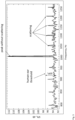
- FIG. 3 exemplarily illustrates the effect of the present invention.
- the abscissae indicates a frequency while the ordinate specifies the sound pressure level.
- the black thick line shows the noise emission in case of propulsion units operated at the same rotational speed and/or having the same number of integrally rotating components. As can be seen therefrom, a significant peak which stands out with respect to the broadband noise arises at one specific frequency and is thus considered as significant noise pollution.
- a sound pressure level of any of the tonal noise frequencies of the at least two propulsion units having a different structure or operated differently is lower than a maximum sound pressure level of a tonal noise frequency of a state in which at least one respective tonal noise frequency of the at least two propulsion unit is the same, that is, the state of the significant peak in the black thick line.
- the sound pressure level of any of the tonal noise frequencies (any of the smaller peaks in dotted lines) of the at least two propulsion units is equal to or lower than the human ear threshold of recognition of tonal noise with respect to the broadband noise.
- the sound pressure level emitted for any tonal noise frequency can be reliably lowered such that the annoyance caused by noise can be decreased.
- the measurement of the perception of a tone above the broadband noise may be performed according to ISO/FDIS 1996-2.
- the number of propulsion units is four.
- the number may be any other number meeting the criterion of at least two.
- the number of propulsion units arranged on both sides of the longitudinal axis is the same, respectively.
- not all of the plurality of propulsion units 4 need to be provided with the structural differences or be operated in a different manner, while at least two do so. In this case, in the formulas only the number of propulsion units having the different structure or being operated in a different manner can be considered.
Landscapes
- Engineering & Computer Science (AREA)
- Aviation & Aerospace Engineering (AREA)
- Control Of Positive-Displacement Air Blowers (AREA)
Priority Applications (1)
| Application Number | Priority Date | Filing Date | Title |
|---|---|---|---|
| EP22164028.7A EP4249373A1 (fr) | 2022-03-24 | 2022-03-24 | Véhicule aérien, procédé de fonctionnement d'un véhicule aérien et dispositif de commande |
Applications Claiming Priority (1)
| Application Number | Priority Date | Filing Date | Title |
|---|---|---|---|
| EP22164028.7A EP4249373A1 (fr) | 2022-03-24 | 2022-03-24 | Véhicule aérien, procédé de fonctionnement d'un véhicule aérien et dispositif de commande |
Publications (1)
| Publication Number | Publication Date |
|---|---|
| EP4249373A1 true EP4249373A1 (fr) | 2023-09-27 |
Family
ID=80933422
Family Applications (1)
| Application Number | Title | Priority Date | Filing Date |
|---|---|---|---|
| EP22164028.7A Pending EP4249373A1 (fr) | 2022-03-24 | 2022-03-24 | Véhicule aérien, procédé de fonctionnement d'un véhicule aérien et dispositif de commande |
Country Status (1)
| Country | Link |
|---|---|
| EP (1) | EP4249373A1 (fr) |
Cited By (1)
| Publication number | Priority date | Publication date | Assignee | Title |
|---|---|---|---|---|
| US20220250742A1 (en) * | 2021-02-08 | 2022-08-11 | Archer Aviation, Inc. | Vertical take-off and landing aircraft with aft rotor tilting |
Citations (7)
| Publication number | Priority date | Publication date | Assignee | Title |
|---|---|---|---|---|
| US6896219B2 (en) * | 2002-03-19 | 2005-05-24 | Dornier Gmbh | Process and apparatus for noise reduction in multi-engine propeller-driven aircraft |
| US9422055B1 (en) * | 2015-09-02 | 2016-08-23 | Amazon Technologies, Inc. | Unmanned aerial vehicle motor driving randomization for noise abatement |
| CA2932597A1 (fr) * | 2015-06-11 | 2016-12-11 | Rolls-Royce North American Technologies, Inc. | Variation de quantites de bornes moteurs en vue de la reduction du bruit |
| US9745050B2 (en) * | 2015-12-18 | 2017-08-29 | Amazon Technologies, Inc. | Selecting propellers for performance and noise shaping |
| US20190185149A1 (en) * | 2017-12-20 | 2019-06-20 | X Development Llc | Multi-rotor tonal noise control for uav |
| EP3543119A1 (fr) * | 2018-03-22 | 2019-09-25 | Aurora Flight Sciences Corporation | Systèmes et procédés permettant de réduire le bruit d'hélice |
| US11174019B2 (en) * | 2017-11-03 | 2021-11-16 | Joby Aero, Inc. | VTOL M-wing configuration |
-
2022
- 2022-03-24 EP EP22164028.7A patent/EP4249373A1/fr active Pending
Patent Citations (7)
| Publication number | Priority date | Publication date | Assignee | Title |
|---|---|---|---|---|
| US6896219B2 (en) * | 2002-03-19 | 2005-05-24 | Dornier Gmbh | Process and apparatus for noise reduction in multi-engine propeller-driven aircraft |
| CA2932597A1 (fr) * | 2015-06-11 | 2016-12-11 | Rolls-Royce North American Technologies, Inc. | Variation de quantites de bornes moteurs en vue de la reduction du bruit |
| US9422055B1 (en) * | 2015-09-02 | 2016-08-23 | Amazon Technologies, Inc. | Unmanned aerial vehicle motor driving randomization for noise abatement |
| US9745050B2 (en) * | 2015-12-18 | 2017-08-29 | Amazon Technologies, Inc. | Selecting propellers for performance and noise shaping |
| US11174019B2 (en) * | 2017-11-03 | 2021-11-16 | Joby Aero, Inc. | VTOL M-wing configuration |
| US20190185149A1 (en) * | 2017-12-20 | 2019-06-20 | X Development Llc | Multi-rotor tonal noise control for uav |
| EP3543119A1 (fr) * | 2018-03-22 | 2019-09-25 | Aurora Flight Sciences Corporation | Systèmes et procédés permettant de réduire le bruit d'hélice |
Non-Patent Citations (2)
| Title |
|---|
| JAMES ?: "Flying a quadcopter with 4 different props", INTERNET CITATION, 14 December 2016 (2016-12-14), XP002792284, Retrieved from the Internet <URL:https://www.propwashed.com/flying-quadcopter-4-different-props/> [retrieved on 20190621] * |
| YANG YANNIAN ET AL: "Experimental study on noise reduction of a wavy multi-copter rotor", APPLIED ACOUSTICS, ELSEVIER PUBLISHING, GB, vol. 165, 19 March 2020 (2020-03-19), XP086150665, ISSN: 0003-682X, [retrieved on 20200319], DOI: 10.1016/J.APACOUST.2020.107311 * |
Cited By (3)
| Publication number | Priority date | Publication date | Assignee | Title |
|---|---|---|---|---|
| US20220250742A1 (en) * | 2021-02-08 | 2022-08-11 | Archer Aviation, Inc. | Vertical take-off and landing aircraft with aft rotor tilting |
| US11919631B2 (en) * | 2021-02-08 | 2024-03-05 | Archer Aviation, Inc. | Vertical take-off and landing aircraft with aft rotor tilting |
| US12434830B2 (en) | 2021-02-08 | 2025-10-07 | Archer Aviation Inc. | Vertical take-off and landing aircraft with AFT rotor tilting |
Similar Documents
| Publication | Publication Date | Title |
|---|---|---|
| EP3381797B1 (fr) | Système de propulsion électrique pour un aéronef | |
| RU2589532C1 (ru) | Гибридный самолет | |
| EP1485290B1 (fr) | Alternateur a aimant permanent destine a une turbine a gaz | |
| US11174035B2 (en) | Hybrid flight vehicle | |
| JP7057264B2 (ja) | ハイブリッド飛行体 | |
| EP4119443B1 (fr) | Aéronef électrique multipropulseur | |
| KR20160146573A (ko) | 소음 감소를 위한 모터 극의 수량의 변화 | |
| EP3403932A1 (fr) | Système de propulsion pour aéronef | |
| CN102933461A (zh) | 用于直升飞机的混合动力驱动装置 | |
| CN112930436A (zh) | 具有无涵道双螺旋桨的涡轮机 | |
| JP2023042141A (ja) | 飛行装置 | |
| EP3680174B1 (fr) | Systèmes de propulsion rotatifs et procédés de propulsion de véhicules à l'aide de systèmes de propulsion rotatifs | |
| EP4249373A1 (fr) | Véhicule aérien, procédé de fonctionnement d'un véhicule aérien et dispositif de commande | |
| EP3691091A1 (fr) | Machine électrique à double rotor | |
| EP1247736A1 (fr) | Aéronef avec un accumulateur rotatif d'énergie méchanique | |
| CN116780733A (zh) | 电源装置 | |
| US20250088054A1 (en) | Axial flux electric motor with rotor cooling | |
| EP4529017A1 (fr) | Ensemble machine électrique et son procédé de fonctionnement | |
| EP3486528A1 (fr) | Engrenage d'entraînement de régulateur et pompe d'inversion | |
| EP3509199A1 (fr) | Manchon de stator de générateur principal pour générateur à entraînement intégré | |
| EP3845464B1 (fr) | Générateur double tension de corps basse pression | |
| CN114368484B (zh) | 空中机动交通工具及其操作方法 | |
| EP4331976B1 (fr) | Dispositif de génération de poussée | |
| EP4480814A1 (fr) | Procédé pour diminuer la signature acoustique d'un système de propulsion électrique hybride | |
| EP4096069A1 (fr) | Turbo-alternateur d'aéronef |
Legal Events
| Date | Code | Title | Description |
|---|---|---|---|
| PUAI | Public reference made under article 153(3) epc to a published international application that has entered the european phase |
Free format text: ORIGINAL CODE: 0009012 |
|
| STAA | Information on the status of an ep patent application or granted ep patent |
Free format text: STATUS: THE APPLICATION HAS BEEN PUBLISHED |
|
| AK | Designated contracting states |
Kind code of ref document: A1 Designated state(s): AL AT BE BG CH CY CZ DE DK EE ES FI FR GB GR HR HU IE IS IT LI LT LU LV MC MK MT NL NO PL PT RO RS SE SI SK SM TR |
|
| STAA | Information on the status of an ep patent application or granted ep patent |
Free format text: STATUS: REQUEST FOR EXAMINATION WAS MADE |
|
| 17P | Request for examination filed |
Effective date: 20240327 |
|
| RBV | Designated contracting states (corrected) |
Designated state(s): AL AT BE BG CH CY CZ DE DK EE ES FI FR GB GR HR HU IE IS IT LI LT LU LV MC MK MT NL NO PL PT RO RS SE SI SK SM TR |
|
| STAA | Information on the status of an ep patent application or granted ep patent |
Free format text: STATUS: EXAMINATION IS IN PROGRESS |
|
| 17Q | First examination report despatched |
Effective date: 20250130 |
|
| 19U | Interruption of proceedings before grant |
Effective date: 20250313 |
|
| 19W | Proceedings resumed before grant after interruption of proceedings |
Effective date: 20260401 |