EP4480814A1 - Procédé pour diminuer la signature acoustique d'un système de propulsion électrique hybride - Google Patents
Procédé pour diminuer la signature acoustique d'un système de propulsion électrique hybride Download PDFInfo
- Publication number
- EP4480814A1 EP4480814A1 EP24180275.0A EP24180275A EP4480814A1 EP 4480814 A1 EP4480814 A1 EP 4480814A1 EP 24180275 A EP24180275 A EP 24180275A EP 4480814 A1 EP4480814 A1 EP 4480814A1
- Authority
- EP
- European Patent Office
- Prior art keywords
- rotor
- fan
- propulsion
- noise
- operating parameters
- Prior art date
- Legal status (The legal status is an assumption and is not a legal conclusion. Google has not performed a legal analysis and makes no representation as to the accuracy of the status listed.)
- Pending
Links
Images


Classifications
-
- B—PERFORMING OPERATIONS; TRANSPORTING
- B64—AIRCRAFT; AVIATION; COSMONAUTICS
- B64U—UNMANNED AERIAL VEHICLES [UAV]; EQUIPMENT THEREFOR
- B64U20/00—Constructional aspects of UAVs
- B64U20/20—Constructional aspects of UAVs for noise reduction
-
- B—PERFORMING OPERATIONS; TRANSPORTING
- B64—AIRCRAFT; AVIATION; COSMONAUTICS
- B64D—EQUIPMENT FOR FITTING IN OR TO AIRCRAFT; FLIGHT SUITS; PARACHUTES; ARRANGEMENT OR MOUNTING OF POWER PLANTS OR PROPULSION TRANSMISSIONS IN AIRCRAFT
- B64D31/00—Power plant control systems; Arrangement of power plant control systems in aircraft
- B64D31/16—Power plant control systems; Arrangement of power plant control systems in aircraft for electric power plants
-
- B—PERFORMING OPERATIONS; TRANSPORTING
- B64—AIRCRAFT; AVIATION; COSMONAUTICS
- B64C—AEROPLANES; HELICOPTERS
- B64C11/00—Propellers, e.g. of ducted type; Features common to propellers and rotors for rotorcraft
- B64C11/46—Arrangements of, or constructional features peculiar to, multiple propellers
- B64C11/48—Units of two or more coaxial propellers
-
- B—PERFORMING OPERATIONS; TRANSPORTING
- B64—AIRCRAFT; AVIATION; COSMONAUTICS
- B64C—AEROPLANES; HELICOPTERS
- B64C11/00—Propellers, e.g. of ducted type; Features common to propellers and rotors for rotorcraft
- B64C11/46—Arrangements of, or constructional features peculiar to, multiple propellers
- B64C11/50—Phase synchronisation between multiple propellers
-
- B—PERFORMING OPERATIONS; TRANSPORTING
- B64—AIRCRAFT; AVIATION; COSMONAUTICS
- B64D—EQUIPMENT FOR FITTING IN OR TO AIRCRAFT; FLIGHT SUITS; PARACHUTES; ARRANGEMENT OR MOUNTING OF POWER PLANTS OR PROPULSION TRANSMISSIONS IN AIRCRAFT
- B64D27/00—Arrangement or mounting of power plants in aircraft; Aircraft characterised by the type or position of power plants
- B64D27/02—Aircraft characterised by the type or position of power plants
- B64D27/30—Aircraft characterised by electric power plants
-
- B—PERFORMING OPERATIONS; TRANSPORTING
- B64—AIRCRAFT; AVIATION; COSMONAUTICS
- B64U—UNMANNED AERIAL VEHICLES [UAV]; EQUIPMENT THEREFOR
- B64U50/00—Propulsion; Power supply
- B64U50/10—Propulsion
- B64U50/19—Propulsion using electrically powered motors
-
- B—PERFORMING OPERATIONS; TRANSPORTING
- B64—AIRCRAFT; AVIATION; COSMONAUTICS
- B64C—AEROPLANES; HELICOPTERS
- B64C2220/00—Active noise reduction systems
-
- G—PHYSICS
- G10—MUSICAL INSTRUMENTS; ACOUSTICS
- G10K—SOUND-PRODUCING DEVICES; METHODS OR DEVICES FOR PROTECTING AGAINST, OR FOR DAMPING, NOISE OR OTHER ACOUSTIC WAVES IN GENERAL; ACOUSTICS NOT OTHERWISE PROVIDED FOR
- G10K2210/00—Details of active noise control [ANC] covered by G10K11/178 but not provided for in any of its subgroups
- G10K2210/10—Applications
- G10K2210/128—Vehicles
- G10K2210/1281—Aircraft, e.g. spacecraft, airplane or helicopter
Definitions
- Exemplary embodiments of the present invention pertain to aircraft and, more particularly, to a system and method for reducing the noise generated by a propulsion unit of an aircraft.
- Hybrid and electric aircraft propulsion technologies have the capability to reduce fossil fuel use, CO 2 emissions, operating costs and noise footprint compared to conventional aircraft.
- the noise generated by the propulsion units of such an aircraft can be problematic. Accordingly, the noise generated by a propulsion unit and experienced on the ground or on board the aircraft may be required to be managed, irrespective of how the propulsion unit is powered.
- a propulsion system includes a propulsion unit including a multi-stage fan having a first fan stage including a first rotor and a second fan stage including a second rotor. At least one propulsion motor is operably coupled to the first rotor and to the second rotor to drive the first rotor and the second rotor about a fan axis.
- a controller is configured to determine a position of at least one of the first rotor and the second rotor in response to an electrical signature of the at least one propulsion motor and adjust one or more operating parameters of at least one of the first rotor and the second rotor to reduce a noise produced by rotation of the first rotor and the noise produced by rotation of the second rotor in combination.
- the controller is further configured to determine the noise produced by at least one of the first rotor and the second rotor.
- the noise produced by at least one of the first rotor and the second rotor is determined in response to the position of at least one of the first rotor and the second rotor.
- the controller is further configured to receive a signal from a sensor indicating the noise produced by at least one of the first rotor and the second rotor.
- the controller is configured to determine a relative position of the first rotor and the second rotor in response to the electrical signature of the at least one propulsion motor.
- the one or more operating parameters of at least one of the first rotor and the second rotor is phase.
- the one or more operating parameters of at least one of the first rotor and the second rotor is rotational speed.
- the propulsion unit is an electric fan.
- the propulsion unit is mounted to an aircraft.
- a method for reducing noise of a propulsion system includes determining a position of at least one rotor of a propulsion unit, the at least one rotor being driven about an axis by at least one propulsion motor in response to an electrical signature of the at least one propulsion motor. Upon determining the position of the at least one rotor, one or more operating parameters of the at least one rotor are adjusted to reduce a noise produced by the propulsion unit.
- the method further comprises determining the noise produced by the at least one rotor.
- the noise produced by the at least one rotor is determined in response to the position of at least one rotor.
- the method further comprises sensing the noise produced by the at least one rotor via a sensor.
- the at least one rotor includes a first rotor and a second rotor and determining the position of the at least one rotor includes determining a relative position of the first rotor and the second rotor.
- the adjusting one or more operating parameters of at least one rotor is performed to lessen the noise generated by one of the first rotor and the second rotor.
- the adjusting one or more operating parameters of at least one rotor includes controlling one or more operating parameters of the second rotor to actively cancel the noise generated by the first rotor.
- the adjusting one or more operating parameters of at least one rotor includes adjusting a phase of the at least one rotor.
- the adjusting one or more operating parameters of at least one rotor includes adjusting a rotational speed of the at least one rotor.
- the propulsion unit is mounted to an aircraft.
- an aircraft includes a fuselage and a propulsion unit mounted to the fuselage.
- the propulsion unit includes a first fan stage having a first rotor and a second fan stage having a second rotor.
- the first rotor and the second rotor are rotatable about a fan axis by at least one propulsion motor.
- a controller is configured to determine a position of at least one of the first rotor and the second rotor in response to an electrical signature of the at least one propulsion motor and adjust one or more operating parameters of at least one of the first rotor and the second rotor to reduce a noise produced by rotation of the first rotor and the noise produced by rotation of the second rotor in combination.
- the system 10 includes a gas turbine engine 12 that is operably connected to an electrical generator 14.
- the operation of the gas turbine engine 12 drives the generator 14, which is operably connected to the gas turbine engine 12 via, for example, an output shaft 16.
- the operation of the generator 14 provides electrical power for the system 10.
- the generator 14 is a permanent magnet generator 14, in which the output voltage of the generator 14 is proportional to the input speed from the output shaft 16 into the generator 14.
- the generator 14 is a wound field synchronous machine with machine output voltage controlled by a Generator Control Unit (GCU).
- GCU Generator Control Unit
- the generator 14 includes a motor-generator 14 configured to generate power and/or drive a spool of the gas turbine engine 12.
- the generator 14 is connected to a power grid 18 of the aircraft, which may be an alternating current (AC) power grid 18 or a direct current (DC) power grid 18.
- the generator 14 is connected to the power grid 18 via a generator voltage regulator 20, which in some embodiments may also include a voltage convertor, such as an active rectifier, to convert the voltage output from the generator 14.
- the system 10 includes at least one propulsion motor 22 connected to the power grid 18, which are driven by electrical power generated by the generator 14.
- the propulsion motors 22 are each connected to a propulsion unit 24, for example a fan, to provide a propulsive force for the aircraft. Additionally, each propulsion motor 22 may be configured to generate power to feed to the power grid 18, such as when the propulsion unit 24 windmills.
- propulsion motor 22 In the illustrated embodiment, three propulsion motor 22 / propulsion unit 24 combinations are included, but one skilled in the art will readily appreciate that other quantities of motor 22 / propulsion unit 24 combinations, such as two, four, or more combinations, may be utilized. Operation of the propulsion motors 22 may be managed by a motor control 26 operably connected to the power grid 18 and the respective propulsion motor 22.
- other aircraft systems 28 may be connected to the power grid 18, such as cabin environmental control systems, lighting, and other systems.
- a power conversion device 30 may be used to interface these other systems to the power grid 18.
- an energy storage system such as one or more batteries 32 and a battery voltage regulator 34 are also connected to the power grid 18 to store excess power generated by the generator 14 and distribute electrical power from the one or more batteries 32 to the power grid 18 and the motors 22 and/or additional aircraft systems 28.
- Each of the generator 14, the batteries 32, the aircraft systems 28, and the propulsion motors 22 are switchably connectible and disconnectable from the power grid 18 via a plurality of switches 36, which may be operated by a system controller 38. It should be appreciated that the hybrid propulsion system illustrated and described herein is intended as an example only.
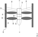
- the propulsion unit 24 may include an outer casing 50, a core or inner casing 52, and a duct 54 defined therebetween.
- the outer casing 50 may be attached to the inner casing 52 via one or more struts 56.
- a plurality of struts 56 may be generally equidistantly spaced about a periphery of the inner casing 52.
- the propulsion unit 24 includes a fan mounted to the inner casing 52 for rotation about an axis.
- the fan is illustrated as being arranged upstream from the struts 56 relative to a flow of air through the propulsion unit 24, it should be appreciated that embodiments where the struts are alternatively or additionally located upstream from the propulsion unit are within the scope of the disclosure.
- the fan is a multi-stage fan, such as having a dual stage configuration including a first fan stage and a second fan stage for example.
- the second fan stage is located downstream from the first fan stage 60 when the propulsion unit 24 is operated to provide thrust.
- the first fan stage 60 and the second fan stage 62 may both be coupled to the same rotatable shaft, such as mounted within the interior of the inner casing for example.
- the plurality of fan stages 60, 62 may be driven about an axis X by a common propulsion motor 22, such as an electrical machine for example.
- the fan stages 60, 62 are driven independently, and controlled by separate propulsion motors 22 are also within the scope of the disclosure.
- the one or more propulsion motors 22 may be mounted at or within the outer casing 50. Accordingly, it should be appreciated that the plurality of fan stages 60, 62 within a propulsion unit 24 may rotate in the same direction or in different directions and/or at the same rotational speed or at different rotational speeds depending on operating conditions.
- Each fan stage 60, 62 includes at least one rotor having a hub and a plurality of fan blades extending radially therefrom.
- the first fan stage 60 includes a first rotor having a first hub 64 and a plurality of first fan blades 66 and the second fan stage 62 includes a second rotor having a second hub 68 and a plurality of second fan blades 70.
- the configuration of the fan rotors may be the same or may be different.
- the number of fan blades 66, 70 of each fan rotor may but need not be the same.
- one or more parameters of the fan blades 66, 70 themselves, such as a shape, diameter, or sweep for example, may vary between the plurality of fans rotors.
- the propulsion unit 24 illustrated and described herein is intended as an example only and that any suitable mechanism having a propeller, fan, rotor, or other suitable member rotatable to generate thrust, such as a propeller, turbofan, or electric fan for example, is within the scope of the disclosure.
- a control system 100 for operating a propulsion unit 24 is illustrated in more detail.
- the fan rotor of each stage may be operably coupled to a separate propulsion motor 22.
- a control system 100 such as including a controller 102 having a processor for example, is operably coupled to one or more propulsion motors 22a, 22b and is configured to send one or more commands thereto and control one or more operating parameters of a respective fan rotor.
- each of the fan stages 60, 62 may be compounded, such as when fan blades from multiple fan stages overlap at a strut 56 or pass a strut simultaneously.
- the controller 102 may be operable to determine a noise generated by the fan rotor of each fan stage 60, 62.
- the control system 100 includes one or more sensors S, such as audio sensors for example, operable to detect or measure a noise level and communicate a signal indicating the detected noise level to the controller 102.
- the control system 100 may include one or more sensors S, such as positioned adjacent to a strut 56 for example, to monitor the overall noise generated by the fan of the propulsion unit 24.
- the control system 100 may include at least one sensor S positioned about the fan, such as at the fan blades 66, 70 for example, to detect the noise generated by the fan rotor of each fan stage 60, 62, respectively.
- the controller 102 may be configured to learn a distortion of the fan blades associated with different operational parameters and the corresponding impact on the noise or acoustic signature of the fan rotor.
- the controller 102 may include a noise estimation module or may be operable to execute a noise estimation algorithm, illustrated, schematically at 104, to estimate the noise generated by a fan rotor of a respective fan stage 60, 62, such as based on one or more operational parameters of the fan rotor.
- the noise estimation module or algorithm 104 referred to collectively as the noise estimation module 104 herein, may be configured to use a position or phase of the fan rotor to evaluate the noise generated thereby.
- an electrical signature is communicated to the controller 102 from the one or more propulsion motors 22.
- the electrical signature may include the phase of the voltage and/or the current provided to a propulsion motor 22 for example, as monitored in real time.
- the electrical signature may be based on an encoder that provides actual rotational speed and/or actual rotational position.
- the controller 102 may determine a position of at least one rotor, and therefore of the fan blades 66, 70 of the fan rotors, operably coupled to each propulsion motor 22. This position of the rotors and/or the fan blades 66, 70 of the fan rotors may then be provided as an input to the noise estimation module 104.
- the controller 102 may be configured to estimate a rotational speed of a propulsion motor 22 and therefore of the corresponding fan rotor based on an electrical signature and provide this rotational speed as an input to the noise estimation module 104.
- the noise estimation module 104 uses the positional information of a fan rotor in combination with one or more additional operational parameters, such as frequency and/or rotational speed of the fan rotor for example, to approximate the noise generated by the fan rotor of each fan stage 60, 62.
- the noise estimation module 104 may access a stored table or database that indicates an approximate noise generated based on one or more operational parameters of a fan rotor, such as position and/or rotational speed for example.
- the controller 102 may additionally include a noise mitigating module or algorithm 106, referred to herein as a noise mitigating module, operable to control at least one fan stage 60, 62 of a propulsion unit 24 to mitigate or reduce the noise generated by the propulsion unit 24.
- a noise mitigating module operable to control at least one fan stage 60, 62 of a propulsion unit 24 to mitigate or reduce the noise generated by the propulsion unit 24.
- the noise mitigating module 106 may alter one or more operational parameters of the propulsion unit 24. Examples of the parameters that may be controlled included to reduce the noise generated by a fan rotor include, but are not limited to modulation, phase, and/or rotational speed of a fan rotor.
- the controller 102 may adjust the phase or angular position between the first rotor and the second rotor to prevent such an overlap from occurring.
- adjusting one or more operating parameters of at least one rotor of the one or more fan stages is actively performed to destructively interfere with the noise generated by another fan stage, resulting in noise cancellation.
- the noise mitigation module 106 may modulate the rotational speed of the fan rotor of the second fan stage 62 such that the second fan rotor, while rotating at the modulated speed, produces anti-noise that destructively interferes with and cancels or substantially cancels the noise generated by rotation of the fan rotor of the first fan stage 60.
- the anti-noise generated by at least one fan stage may include sound waves that have approximately the same frequency and/or amplitude as the noise sound waves generated by another fan stage. However, the phase of the anti-noise sound waves may be different than the phase of the noise sound waves.
- the noise mitigating module is illustrated and described herein with respect to reducing the noise generated by a propulsion unit 24, it should be appreciated that the noise mitigating module may alternatively or additionally be configured to reduce the noise generated by a group of propulsion units 24, such as all or only a portion of the propulsion units 24 of a vehicle.
Landscapes
- Engineering & Computer Science (AREA)
- Aviation & Aerospace Engineering (AREA)
- Chemical & Material Sciences (AREA)
- Combustion & Propulsion (AREA)
- Mechanical Engineering (AREA)
- Remote Sensing (AREA)
- Control Of Positive-Displacement Air Blowers (AREA)
- Control Of Multiple Motors (AREA)
Applications Claiming Priority (1)
| Application Number | Priority Date | Filing Date | Title |
|---|---|---|---|
| US18/340,341 US20240425190A1 (en) | 2023-06-23 | 2023-06-23 | Method to decrease acoustic signature of a hybrid electric propulsion system |
Publications (1)
| Publication Number | Publication Date |
|---|---|
| EP4480814A1 true EP4480814A1 (fr) | 2024-12-25 |
Family
ID=91431498
Family Applications (1)
| Application Number | Title | Priority Date | Filing Date |
|---|---|---|---|
| EP24180275.0A Pending EP4480814A1 (fr) | 2023-06-23 | 2024-06-05 | Procédé pour diminuer la signature acoustique d'un système de propulsion électrique hybride |
Country Status (2)
| Country | Link |
|---|---|
| US (1) | US20240425190A1 (fr) |
| EP (1) | EP4480814A1 (fr) |
Citations (8)
| Publication number | Priority date | Publication date | Assignee | Title |
|---|---|---|---|---|
| US20160083073A1 (en) * | 2014-09-23 | 2016-03-24 | Amazon Technologies, Inc. | Vehicle noise control and communication |
| US20170274993A1 (en) * | 2016-03-23 | 2017-09-28 | Amazon Technologies, Inc. | Aerial vehicle with different propeller blade configurations |
| US20190161169A1 (en) * | 2017-11-27 | 2019-05-30 | United States Of America As Represented By The Administrator Of Nasa | Adaptive Phase Control Architecture for Reduction of Community Noise from Distributed Propulsion Vehicles |
| US20200269990A1 (en) * | 2018-06-01 | 2020-08-27 | Joby Aero, Inc. | System and method for aircraft noise mitigation |
| US20210139138A1 (en) * | 2019-11-11 | 2021-05-13 | Beta Air Llc | Methods and systems for reducing rotor acoustics of an aircraft |
| US20220055742A1 (en) * | 2019-04-26 | 2022-02-24 | Aergility Corporation | Hybrid gyrodyne aircraft |
| CA3195186A1 (fr) * | 2020-10-09 | 2022-04-14 | Greenjets Limited | Propulseur a soufflante carenee electrique |
| US20220194557A1 (en) * | 2020-12-17 | 2022-06-23 | Aurora Flight Sciences Corporation, a subsidiary of The Boeing Company | Aircraft rotor assembly with plural rotors |
Family Cites Families (19)
| Publication number | Priority date | Publication date | Assignee | Title |
|---|---|---|---|---|
| GB1252193A (fr) * | 1969-09-26 | 1971-11-03 | ||
| US4156344A (en) * | 1976-12-27 | 1979-05-29 | The Boeing Company | Inlet guide vane bleed system |
| US5027277A (en) * | 1989-04-11 | 1991-06-25 | United Technologies Corporation | Method for synchrophaser measurement and synchrophaser control |
| US5148402A (en) * | 1990-12-21 | 1992-09-15 | United Technologies Corporation | Method for reducing aircraft cabin noise and vibration |
| DE10212036B4 (de) * | 2002-03-19 | 2009-01-02 | Eads Deutschland Gmbh | Verfahren zur Geräuschreduktion für mehrmotorige Propellerflugzeuge |
| FR2905356B1 (fr) * | 2006-09-05 | 2008-11-07 | Airbus France Sas | Procede pour la realisation d'un aeronef a impact environnemental reduit et aeronef obtenu |
| US7932691B2 (en) * | 2008-04-22 | 2011-04-26 | GM Global Technology Operations LLC | Permanent magnet motor start-up |
| DE102009007013A1 (de) * | 2009-01-31 | 2010-08-12 | Deutsches Zentrum für Luft- und Raumfahrt e.V. | Triebwerk, insbesondere CROR-Antrieb, für ein Flugzeug |
| GB2482333A (en) * | 2010-07-30 | 2012-02-01 | Ge Aviat Systems Ltd | Aircraft propeller |
| GB201101609D0 (en) * | 2011-01-31 | 2011-03-16 | Rolls Royce Plc | Attenuation of open rotor noise |
| US8912743B2 (en) * | 2011-11-01 | 2014-12-16 | Simmonds Precision Products, Inc. | Apparatus and method of determining rotor position in a salient-type motor |
| US20170274984A1 (en) * | 2016-03-23 | 2017-09-28 | Amazon Technologies, Inc. | Coaxially aligned propellers of an aerial vehicle |
| US10583914B2 (en) * | 2016-03-23 | 2020-03-10 | Amazon Technologies, Inc. | Telescoping propeller blades for aerial vehicles |
| US10714069B1 (en) * | 2016-05-03 | 2020-07-14 | Wing Aviation Llc | Systems and methods for tuning propeller noise |
| FR3068742B1 (fr) * | 2017-07-07 | 2021-09-10 | Safran Aircraft Engines | Aube de turbomachine comprenant une source electroacoustique a montage ameliore, rangee d'aubes directrices de sortie et turbomachine comprenant une telle aube |
| US11174019B2 (en) * | 2017-11-03 | 2021-11-16 | Joby Aero, Inc. | VTOL M-wing configuration |
| US20210009263A1 (en) * | 2019-07-12 | 2021-01-14 | Dotterel Technologies Limited | Rotor system |
| US20250350216A1 (en) * | 2024-05-10 | 2025-11-13 | Beta Air, Llc | Motor reboot after shutdown in flight |
| US20250388331A1 (en) * | 2024-06-24 | 2025-12-25 | Beta Air, Llc | Motor health monitoring |
-
2023
- 2023-06-23 US US18/340,341 patent/US20240425190A1/en active Pending
-
2024
- 2024-06-05 EP EP24180275.0A patent/EP4480814A1/fr active Pending
Patent Citations (8)
| Publication number | Priority date | Publication date | Assignee | Title |
|---|---|---|---|---|
| US20160083073A1 (en) * | 2014-09-23 | 2016-03-24 | Amazon Technologies, Inc. | Vehicle noise control and communication |
| US20170274993A1 (en) * | 2016-03-23 | 2017-09-28 | Amazon Technologies, Inc. | Aerial vehicle with different propeller blade configurations |
| US20190161169A1 (en) * | 2017-11-27 | 2019-05-30 | United States Of America As Represented By The Administrator Of Nasa | Adaptive Phase Control Architecture for Reduction of Community Noise from Distributed Propulsion Vehicles |
| US20200269990A1 (en) * | 2018-06-01 | 2020-08-27 | Joby Aero, Inc. | System and method for aircraft noise mitigation |
| US20220055742A1 (en) * | 2019-04-26 | 2022-02-24 | Aergility Corporation | Hybrid gyrodyne aircraft |
| US20210139138A1 (en) * | 2019-11-11 | 2021-05-13 | Beta Air Llc | Methods and systems for reducing rotor acoustics of an aircraft |
| CA3195186A1 (fr) * | 2020-10-09 | 2022-04-14 | Greenjets Limited | Propulseur a soufflante carenee electrique |
| US20220194557A1 (en) * | 2020-12-17 | 2022-06-23 | Aurora Flight Sciences Corporation, a subsidiary of The Boeing Company | Aircraft rotor assembly with plural rotors |
Also Published As
| Publication number | Publication date |
|---|---|
| US20240425190A1 (en) | 2024-12-26 |
Similar Documents
| Publication | Publication Date | Title |
|---|---|---|
| EP3246525B1 (fr) | Moteurs à turbine à gaz ayant une commande de flottement | |
| CA2759191C (fr) | Combine generateur a corps basse pression et generateur a turbine a air dynamique | |
| EP3381797B1 (fr) | Système de propulsion électrique pour un aéronef | |
| JP6800182B2 (ja) | 航空機用推進システム | |
| EP3104519B1 (fr) | Variation des quantités de pôles de moteur pour la réduction du bruit | |
| CA2913526C (fr) | Ensemble moteur a reaction et procede de generation d'electricite | |
| JP6990477B1 (ja) | 飛行装置 | |
| CN103089550A (zh) | 风力涡轮机及为风力涡轮机的涡轮机叶片除冰的方法 | |
| JP2020069975A (ja) | ハイブリッド飛行体 | |
| EP2977314A1 (fr) | Génération et commande de puissance d'hélice dans un moyeu | |
| US11884416B2 (en) | Electric generator | |
| JP2020082755A (ja) | ハイブリッド飛行体 | |
| CN114513000A (zh) | 电力系统 | |
| EP4480814A1 (fr) | Procédé pour diminuer la signature acoustique d'un système de propulsion électrique hybride | |
| EP4529017A1 (fr) | Ensemble machine électrique et son procédé de fonctionnement | |
| EP3845464B1 (fr) | Générateur double tension de corps basse pression | |
| EP4249373A1 (fr) | Véhicule aérien, procédé de fonctionnement d'un véhicule aérien et dispositif de commande | |
| US20090033099A1 (en) | Device for supplying electricity | |
| EP4589799A1 (fr) | Couplage d'alimentation électrique d'aéronef à une charge | |
| EP4699936A2 (fr) | Mesure du rendement dans un système d'alimentation électrique pour un système de propulsion d'aéronef | |
| CN116292134B (zh) | 三轴双驱变桨地面测试系统 | |
| JPH05338593A (ja) | 航空機の風車式発電装置 | |
| CN121361582A (zh) | 用于飞行器的紧急动力产生系统、飞行器机身部段、飞行器机翼部段以及飞行器 | |
| CN119145959A (zh) | 用于有效地确定推进系统中的相移的系统和方法 |
Legal Events
| Date | Code | Title | Description |
|---|---|---|---|
| PUAI | Public reference made under article 153(3) epc to a published international application that has entered the european phase |
Free format text: ORIGINAL CODE: 0009012 |
|
| STAA | Information on the status of an ep patent application or granted ep patent |
Free format text: STATUS: THE APPLICATION HAS BEEN PUBLISHED |
|
| AK | Designated contracting states |
Kind code of ref document: A1 Designated state(s): AL AT BE BG CH CY CZ DE DK EE ES FI FR GB GR HR HU IE IS IT LI LT LU LV MC ME MK MT NL NO PL PT RO RS SE SI SK SM TR |
|
| STAA | Information on the status of an ep patent application or granted ep patent |
Free format text: STATUS: REQUEST FOR EXAMINATION WAS MADE |
|
| 17P | Request for examination filed |
Effective date: 20250625 |
|
| STAA | Information on the status of an ep patent application or granted ep patent |
Free format text: STATUS: EXAMINATION IS IN PROGRESS |
|
| 17Q | First examination report despatched |
Effective date: 20260112 |