EP4253103A1 - Herstellungsverfahren für eine schwingungsdämpfende vorrichtung, stopper für eine schwingungsdämpfende vorrichtung und schwingungsdämpfende vorrichtung - Google Patents
Herstellungsverfahren für eine schwingungsdämpfende vorrichtung, stopper für eine schwingungsdämpfende vorrichtung und schwingungsdämpfende vorrichtung Download PDFInfo
- Publication number
- EP4253103A1 EP4253103A1 EP21897445.9A EP21897445A EP4253103A1 EP 4253103 A1 EP4253103 A1 EP 4253103A1 EP 21897445 A EP21897445 A EP 21897445A EP 4253103 A1 EP4253103 A1 EP 4253103A1
- Authority
- EP
- European Patent Office
- Prior art keywords
- stopper
- bracket
- vibration device
- vibration
- positioning protrusion
- Prior art date
- Legal status (The legal status is an assumption and is not a legal conclusion. Google has not performed a legal analysis and makes no representation as to the accuracy of the status listed.)
- Pending
Links
Images


Classifications
-
- B—PERFORMING OPERATIONS; TRANSPORTING
- B60—VEHICLES IN GENERAL
- B60G—VEHICLE SUSPENSION ARRANGEMENTS
- B60G7/00—Pivoted suspension arms; Accessories thereof
- B60G7/02—Attaching arms to sprung part of vehicle
-
- F—MECHANICAL ENGINEERING; LIGHTING; HEATING; WEAPONS; BLASTING
- F16—ENGINEERING ELEMENTS AND UNITS; GENERAL MEASURES FOR PRODUCING AND MAINTAINING EFFECTIVE FUNCTIONING OF MACHINES OR INSTALLATIONS; THERMAL INSULATION IN GENERAL
- F16F—SPRINGS; SHOCK-ABSORBERS; MEANS FOR DAMPING VIBRATION
- F16F15/00—Suppression of vibrations in systems; Means or arrangements for avoiding or reducing out-of-balance forces, e.g. due to motion
- F16F15/02—Suppression of vibrations of non-rotating, e.g. reciprocating systems; Suppression of vibrations of rotating systems by use of members not moving with the rotating systems
- F16F15/04—Suppression of vibrations of non-rotating, e.g. reciprocating systems; Suppression of vibrations of rotating systems by use of members not moving with the rotating systems using elastic means
- F16F15/08—Suppression of vibrations of non-rotating, e.g. reciprocating systems; Suppression of vibrations of rotating systems by use of members not moving with the rotating systems using elastic means with rubber springs ; with springs made of rubber and metal
-
- F—MECHANICAL ENGINEERING; LIGHTING; HEATING; WEAPONS; BLASTING
- F16—ENGINEERING ELEMENTS AND UNITS; GENERAL MEASURES FOR PRODUCING AND MAINTAINING EFFECTIVE FUNCTIONING OF MACHINES OR INSTALLATIONS; THERMAL INSULATION IN GENERAL
- F16B—DEVICES FOR FASTENING OR SECURING CONSTRUCTIONAL ELEMENTS OR MACHINE PARTS TOGETHER, e.g. NAILS, BOLTS, CIRCLIPS, CLAMPS, CLIPS OR WEDGES; JOINTS OR JOINTING
- F16B2/00—Friction-grip releasable fastenings
- F16B2/20—Clips, i.e. with gripping action effected solely by the inherent resistance to deformation of the material of the fastening
- F16B2/22—Clips, i.e. with gripping action effected solely by the inherent resistance to deformation of the material of the fastening of resilient material, e.g. rubbery material
-
- F—MECHANICAL ENGINEERING; LIGHTING; HEATING; WEAPONS; BLASTING
- F16—ENGINEERING ELEMENTS AND UNITS; GENERAL MEASURES FOR PRODUCING AND MAINTAINING EFFECTIVE FUNCTIONING OF MACHINES OR INSTALLATIONS; THERMAL INSULATION IN GENERAL
- F16B—DEVICES FOR FASTENING OR SECURING CONSTRUCTIONAL ELEMENTS OR MACHINE PARTS TOGETHER, e.g. NAILS, BOLTS, CIRCLIPS, CLAMPS, CLIPS OR WEDGES; JOINTS OR JOINTING
- F16B4/00—Shrinkage connections, e.g. assembled with the parts at different temperature; Force fits; Non-releasable friction-grip fastenings
- F16B4/004—Press fits, force fits, interference fits, i.e. fits without heat or chemical treatment
-
- F—MECHANICAL ENGINEERING; LIGHTING; HEATING; WEAPONS; BLASTING
- F16—ENGINEERING ELEMENTS AND UNITS; GENERAL MEASURES FOR PRODUCING AND MAINTAINING EFFECTIVE FUNCTIONING OF MACHINES OR INSTALLATIONS; THERMAL INSULATION IN GENERAL
- F16B—DEVICES FOR FASTENING OR SECURING CONSTRUCTIONAL ELEMENTS OR MACHINE PARTS TOGETHER, e.g. NAILS, BOLTS, CIRCLIPS, CLAMPS, CLIPS OR WEDGES; JOINTS OR JOINTING
- F16B5/00—Joining sheets or plates, e.g. panels, to one another or to strips or bars parallel to them
- F16B5/07—Joining sheets or plates, e.g. panels, to one another or to strips or bars parallel to them by means of multiple interengaging protrusions on the surfaces, e.g. hooks, coils
-
- F—MECHANICAL ENGINEERING; LIGHTING; HEATING; WEAPONS; BLASTING
- F16—ENGINEERING ELEMENTS AND UNITS; GENERAL MEASURES FOR PRODUCING AND MAINTAINING EFFECTIVE FUNCTIONING OF MACHINES OR INSTALLATIONS; THERMAL INSULATION IN GENERAL
- F16B—DEVICES FOR FASTENING OR SECURING CONSTRUCTIONAL ELEMENTS OR MACHINE PARTS TOGETHER, e.g. NAILS, BOLTS, CIRCLIPS, CLAMPS, CLIPS OR WEDGES; JOINTS OR JOINTING
- F16B9/00—Connections of rods or tubular parts to flat surfaces at an angle
- F16B9/05—Connections of rods or tubular parts to flat surfaces at an angle by way of an intermediate member
- F16B9/056—Connections of rods or tubular parts to flat surfaces at an angle by way of an intermediate member the intermediate member extending through the flat surface; the rod or tubular part extending through the flat surface
-
- F—MECHANICAL ENGINEERING; LIGHTING; HEATING; WEAPONS; BLASTING
- F16—ENGINEERING ELEMENTS AND UNITS; GENERAL MEASURES FOR PRODUCING AND MAINTAINING EFFECTIVE FUNCTIONING OF MACHINES OR INSTALLATIONS; THERMAL INSULATION IN GENERAL
- F16B—DEVICES FOR FASTENING OR SECURING CONSTRUCTIONAL ELEMENTS OR MACHINE PARTS TOGETHER, e.g. NAILS, BOLTS, CIRCLIPS, CLAMPS, CLIPS OR WEDGES; JOINTS OR JOINTING
- F16B9/00—Connections of rods or tubular parts to flat surfaces at an angle
- F16B9/07—Connections of rods or tubular parts to flat surfaces at an angle involving plastic or elastic deformation when assembling
-
- F—MECHANICAL ENGINEERING; LIGHTING; HEATING; WEAPONS; BLASTING
- F16—ENGINEERING ELEMENTS AND UNITS; GENERAL MEASURES FOR PRODUCING AND MAINTAINING EFFECTIVE FUNCTIONING OF MACHINES OR INSTALLATIONS; THERMAL INSULATION IN GENERAL
- F16F—SPRINGS; SHOCK-ABSORBERS; MEANS FOR DAMPING VIBRATION
- F16F1/00—Springs
- F16F1/36—Springs made of rubber or other material having high internal friction, e.g. thermoplastic elastomers
- F16F1/38—Springs made of rubber or other material having high internal friction, e.g. thermoplastic elastomers with a sleeve of elastic material between a rigid outer sleeve and a rigid inner sleeve or pin, i.e. bushing-type
- F16F1/3807—Springs made of rubber or other material having high internal friction, e.g. thermoplastic elastomers with a sleeve of elastic material between a rigid outer sleeve and a rigid inner sleeve or pin, i.e. bushing-type characterised by adaptations for particular modes of stressing
- F16F1/3814—Springs made of rubber or other material having high internal friction, e.g. thermoplastic elastomers with a sleeve of elastic material between a rigid outer sleeve and a rigid inner sleeve or pin, i.e. bushing-type characterised by adaptations for particular modes of stressing characterised by adaptations to counter axial forces
-
- F—MECHANICAL ENGINEERING; LIGHTING; HEATING; WEAPONS; BLASTING
- F16—ENGINEERING ELEMENTS AND UNITS; GENERAL MEASURES FOR PRODUCING AND MAINTAINING EFFECTIVE FUNCTIONING OF MACHINES OR INSTALLATIONS; THERMAL INSULATION IN GENERAL
- F16F—SPRINGS; SHOCK-ABSORBERS; MEANS FOR DAMPING VIBRATION
- F16F1/00—Springs
- F16F1/36—Springs made of rubber or other material having high internal friction, e.g. thermoplastic elastomers
- F16F1/38—Springs made of rubber or other material having high internal friction, e.g. thermoplastic elastomers with a sleeve of elastic material between a rigid outer sleeve and a rigid inner sleeve or pin, i.e. bushing-type
- F16F1/3828—End stop features or buffering
-
- F—MECHANICAL ENGINEERING; LIGHTING; HEATING; WEAPONS; BLASTING
- F16—ENGINEERING ELEMENTS AND UNITS; GENERAL MEASURES FOR PRODUCING AND MAINTAINING EFFECTIVE FUNCTIONING OF MACHINES OR INSTALLATIONS; THERMAL INSULATION IN GENERAL
- F16F—SPRINGS; SHOCK-ABSORBERS; MEANS FOR DAMPING VIBRATION
- F16F1/00—Springs
- F16F1/36—Springs made of rubber or other material having high internal friction, e.g. thermoplastic elastomers
- F16F1/38—Springs made of rubber or other material having high internal friction, e.g. thermoplastic elastomers with a sleeve of elastic material between a rigid outer sleeve and a rigid inner sleeve or pin, i.e. bushing-type
- F16F1/3842—Method of assembly, production or treatment; Mounting thereof
-
- B—PERFORMING OPERATIONS; TRANSPORTING
- B60—VEHICLES IN GENERAL
- B60G—VEHICLE SUSPENSION ARRANGEMENTS
- B60G2204/00—Indexing codes related to suspensions per se or to auxiliary parts
- B60G2204/40—Auxiliary suspension parts; Adjustment of suspensions
- B60G2204/41—Elastic mounts, e.g. bushings
-
- B—PERFORMING OPERATIONS; TRANSPORTING
- B60—VEHICLES IN GENERAL
- B60G—VEHICLE SUSPENSION ARRANGEMENTS
- B60G2204/00—Indexing codes related to suspensions per se or to auxiliary parts
- B60G2204/40—Auxiliary suspension parts; Adjustment of suspensions
- B60G2204/41—Elastic mounts, e.g. bushings
- B60G2204/4108—Resilient element being enclosed and or pres-tressed in a solid container
-
- B—PERFORMING OPERATIONS; TRANSPORTING
- B60—VEHICLES IN GENERAL
- B60G—VEHICLE SUSPENSION ARRANGEMENTS
- B60G2204/00—Indexing codes related to suspensions per se or to auxiliary parts
- B60G2204/40—Auxiliary suspension parts; Adjustment of suspensions
- B60G2204/44—Centering or positioning means
- B60G2204/4402—Spacers or shims
-
- B—PERFORMING OPERATIONS; TRANSPORTING
- B60—VEHICLES IN GENERAL
- B60G—VEHICLE SUSPENSION ARRANGEMENTS
- B60G2206/00—Indexing codes related to the manufacturing of suspensions: constructional features, the materials used, procedures or tools
- B60G2206/01—Constructional features of suspension elements, e.g. arms, dampers, springs
- B60G2206/80—Manufacturing procedures
- B60G2206/82—Joining
-
- B—PERFORMING OPERATIONS; TRANSPORTING
- B60—VEHICLES IN GENERAL
- B60G—VEHICLE SUSPENSION ARRANGEMENTS
- B60G2206/00—Indexing codes related to the manufacturing of suspensions: constructional features, the materials used, procedures or tools
- B60G2206/01—Constructional features of suspension elements, e.g. arms, dampers, springs
- B60G2206/80—Manufacturing procedures
- B60G2206/82—Joining
- B60G2206/8207—Joining by screwing
-
- B—PERFORMING OPERATIONS; TRANSPORTING
- B60—VEHICLES IN GENERAL
- B60G—VEHICLE SUSPENSION ARRANGEMENTS
- B60G2206/00—Indexing codes related to the manufacturing of suspensions: constructional features, the materials used, procedures or tools
- B60G2206/01—Constructional features of suspension elements, e.g. arms, dampers, springs
- B60G2206/90—Maintenance
- B60G2206/91—Assembly procedures
-
- F—MECHANICAL ENGINEERING; LIGHTING; HEATING; WEAPONS; BLASTING
- F16—ENGINEERING ELEMENTS AND UNITS; GENERAL MEASURES FOR PRODUCING AND MAINTAINING EFFECTIVE FUNCTIONING OF MACHINES OR INSTALLATIONS; THERMAL INSULATION IN GENERAL
- F16B—DEVICES FOR FASTENING OR SECURING CONSTRUCTIONAL ELEMENTS OR MACHINE PARTS TOGETHER, e.g. NAILS, BOLTS, CIRCLIPS, CLAMPS, CLIPS OR WEDGES; JOINTS OR JOINTING
- F16B21/00—Means for preventing relative axial movement of a pin, spigot, shaft or the like and a member surrounding it; Stud-and-socket releasable fastenings
- F16B21/06—Releasable fastening devices with snap-action
- F16B21/08—Releasable fastening devices with snap-action in which the stud, pin, or spigot has a resilient part
- F16B21/086—Releasable fastening devices with snap-action in which the stud, pin, or spigot has a resilient part the shank of the stud, pin or spigot having elevations, ribs, fins or prongs intended for deformation or tilting predominantly in a direction perpendicular to the direction of insertion
-
- F—MECHANICAL ENGINEERING; LIGHTING; HEATING; WEAPONS; BLASTING
- F16—ENGINEERING ELEMENTS AND UNITS; GENERAL MEASURES FOR PRODUCING AND MAINTAINING EFFECTIVE FUNCTIONING OF MACHINES OR INSTALLATIONS; THERMAL INSULATION IN GENERAL
- F16B—DEVICES FOR FASTENING OR SECURING CONSTRUCTIONAL ELEMENTS OR MACHINE PARTS TOGETHER, e.g. NAILS, BOLTS, CIRCLIPS, CLAMPS, CLIPS OR WEDGES; JOINTS OR JOINTING
- F16B2200/00—Constructional details of connections not covered for in other groups of this subclass
- F16B2200/79—Friction-reducing coatings
-
- F—MECHANICAL ENGINEERING; LIGHTING; HEATING; WEAPONS; BLASTING
- F16—ENGINEERING ELEMENTS AND UNITS; GENERAL MEASURES FOR PRODUCING AND MAINTAINING EFFECTIVE FUNCTIONING OF MACHINES OR INSTALLATIONS; THERMAL INSULATION IN GENERAL
- F16F—SPRINGS; SHOCK-ABSORBERS; MEANS FOR DAMPING VIBRATION
- F16F2226/00—Manufacturing; Treatments
- F16F2226/02—Surface treatments
-
- F—MECHANICAL ENGINEERING; LIGHTING; HEATING; WEAPONS; BLASTING
- F16—ENGINEERING ELEMENTS AND UNITS; GENERAL MEASURES FOR PRODUCING AND MAINTAINING EFFECTIVE FUNCTIONING OF MACHINES OR INSTALLATIONS; THERMAL INSULATION IN GENERAL
- F16F—SPRINGS; SHOCK-ABSORBERS; MEANS FOR DAMPING VIBRATION
- F16F2226/00—Manufacturing; Treatments
- F16F2226/04—Assembly or fixing methods; methods to form or fashion parts
- F16F2226/044—Snapping
-
- F—MECHANICAL ENGINEERING; LIGHTING; HEATING; WEAPONS; BLASTING
- F16—ENGINEERING ELEMENTS AND UNITS; GENERAL MEASURES FOR PRODUCING AND MAINTAINING EFFECTIVE FUNCTIONING OF MACHINES OR INSTALLATIONS; THERMAL INSULATION IN GENERAL
- F16F—SPRINGS; SHOCK-ABSORBERS; MEANS FOR DAMPING VIBRATION
- F16F2230/00—Purpose; Design features
- F16F2230/04—Lubrication
Definitions
- the present disclosure relates to an anti-vibration device manufacturing method, a stopper for an anti-vibration device, and an anti-vibration device.
- a conventional anti-vibration device include an anti-vibration mount in which the stopper body is fastened to the bracket, by pressing a positioning protrusion (insertion portion) of the stopper body (rubber stopper) into a positioning hole (fastening hole) formed in the bracket, so that a bulging portion (flange portion) of the positioning protrusion is prevented from detaching from the bracket (for example, Patent Literature 1).
- the positioning protrusion of the conventional anti-vibration device is made of rubber, in a case in which the rubber is low in hardness and too soft, it may deform excessively, and when the bulging portion of the positioning protrusion is pressed into the positioning hole for press-fitting, the press-fit (insertion) characteristics may deteriorate.
- a lubricant is applied to the positioning protrusion, the insertion characteristics can be improved.
- the use of the lubricant may also decrease the amount of force (hereinafter also referred to as "detaching force") required to detach the positioning protrusion. That is, the conventional anti-vibration device does not prevent easy separation between the stopper and bracket, while improving the ease of fastening the stopper and the bracket together.
- an anti-vibration device manufacturing method for obtaining the anti-vibration device in which easy separation between the stopper and the bracket is prevented, while the ease of fastening the stopper and the bracket together is improved, a stopper for an anti-vibration device in which easy separation between the stopper and the bracket is prevented, while the ease of fastening the stopper and the bracket together is improved, and an anti-vibration device in which easy separation between the stopper and the bracket is prevented, while the ease of fastening the stopper and the bracket together is improved.
- An anti-vibration device manufacturing method for obtaining the anti-vibration device including: an anti-vibration body including an inner cylinder, an outer cylinder, and an elastic body connecting the inner cylinder and the outer cylinder; a bracket arranged on one side of the anti-vibration body in an axial direction; and a stopper arranged between the anti-vibration body and the bracket, the anti-vibration device manufacturing method including:
- the coating agent preferably is a rust inhibitor.
- the anti-vibration device manufacturing method is superior in terms of workability and cost-effectiveness.
- the coating agent is preferably applied to the entire positioning protrusion.
- the anti-vibration device manufacturing method is even more superior in terms of workability and cost-effectiveness
- a stopper for an anti-vibration device is a stopper for an anti-vibration device that is to be used in the anti-vibration device including: an anti-vibration body including an inner cylinder, an outer cylinder, and an elastic body connecting the inner cylinder and the outer cylinder; a bracket arranged on one side of the anti-vibration body in an axial direction; and the stopper arranged between the anti-vibration body and the bracket, the stopper including:
- the coating portion is preferably formed of a rust inhibitor.
- the stopper for an anti-vibration device is superior in terms of manufacturability and cost-effectiveness.
- An anti-vibration device includes:
- the coating portion is preferably formed of a rust inhibitor.
- the anti-vibration device is superior in terms of manufacturability and cost-effectiveness.
- the coating portion is preferably positioned on the surface of the bulging portion that is located on one side in the axial direction.
- the coating portion can be visible as a marker indicating that the bracket and the stopper will not easily separate from each other, for example, even when they are handled, with the positioning protrusion being prevented from detaching from the bracket.
- an anti-vibration device manufacturing method for obtaining the anti-vibration device in which easy separation between the stopper and the bracket is prevented, while the ease of fastening the stopper and the bracket together is improved, a stopper for an anti-vibration device in which easy separation between the stopper and the bracket is prevented, while the ease of fastening the stopper and the bracket together is improved, and an anti-vibration device in which easy separation between the stopper and the bracket is prevented, while the ease of fastening the stopper and the bracket together is improved can be provided.
- an anti-vibration device manufacturing method a stopper of an anti-vibration device, and an anti-vibration device according to an embodiment of the present disclosure will be described below.
- FIG. 1 illustrates an anti-vibration device 1 according to an embodiment of the present disclosure.
- the anti-vibration device 1 is a suspension bushing for a vehicle.
- a suspension member 30 is attached to a vehicle body 40 via the anti-vibration device 1.
- FIG. 1 illustrates a plane including an axis line O of the anti-vibration device 1 as a cross-section.
- a direction in which the axis line O extends is referred to as an axial direction.
- a circumferential direction refers to a direction extending around the axis line O.
- one side in the axial direction refers to either an upper side of the drawing or a lower side of the drawing along the axial direction in FIG. 1 .
- a side directed toward the lower side of the drawing along the axial direction (hereinafter also referred to as “downward") is the one side in the axial direction
- a side directed toward the upper side of the drawing along the axial direction (hereinafter also referred to as "upward) is the other side in the axial direction.
- a direction perpendicular to the axial direction is referred to as a perpendicular-to-axis direction.
- the side directed toward the axis line O is referred to as the inner side in the perpendicular-to-axis direction
- the side directed away from the axis line O is referred to as the outer side in the axial direction.
- the anti-vibration device 1 includes an anti-vibration body 1A.
- the anti-vibration body 1A includes an inner cylinder 2, an outer cylinder 3, and an elastic body 4 connecting the inner cylinder 2 and the outer cylinder 3.
- the inner cylinder 2 has a through hole A2 extending in the axial direction.
- a bolt shaft 15a can be passed through the through hole A2, as will be described later.
- the inner cylinder 2 is a cylindrical member having the through hole A2 formed therein.
- the inner cylinder 2 is a cylindrical member.
- the inner cylinder 2, which has the through hole A2 formed therein is not limited to a cylindrical member.
- the outer cylinder 3 is arranged so as to circumferentially surround at least part of the inner cylinder 2.
- the outer cylinder 3 has a body portion 3a extending in the axial direction.
- a through hole extending in the axial direction is formed inside the body portion 3a.
- the inner cylinder 2 can be arranged coaxially with the axis line O.
- the outer cylinder 3 has an upper end portion 3b extending to the outer side in the axial direction.
- the upper end portion 3b forms an upper end portion of the body portion 3a and extends annularly in the circumferential direction around the entire circumference.
- the elastic body 4 is formed of an elastic material.
- the elastic body 4 is arranged between the inner cylinder 2 and the outer cylinder 3.
- the elastic body 4 connects the inner cylinder 2 and the outer cylinder 3.
- the anti-vibration device 1 further includes a bracket 5.
- the bracket 5 is arranged on one side of the anti-vibration body 1A in the axial direction.
- the anti-vibration device 1 further includes a stopper 6.
- the stopper 6 is arranged between the anti-vibration body 1A and the bracket 5.
- the body 40 is arranged above the anti-vibration device 1, and because it is configured to be screwed upward from below as will be described later, the bracket 5 is arranged below the anti-vibration body 1A.
- the bracket 5 can be arranged above the anti-vibration body 1A.
- the bracket 5 has positioning holes A1 formed therein that penetrate in the axial direction.
- the bracket 5 also has an opening A5 formed therein.
- the bolt shaft 15a can be passed through the opening A5, as will be described later.
- the bracket 5 is a plate member.
- the bracket 5 can be a frame of a vehicle.
- the stopper 6 includes a rigid member 7 having an opening A6 formed therein, and an elastic member 8.
- the rigid member 7 is a member formed of a rigid material.
- the rigid material refers to a material that is not easily deformed by action of force.
- the rigid material is a metallic material. Examples of metallic materials include aluminum alloys, carbon steel, stainless steel, and other steels.
- the bolt shaft 15a can be passed through the opening A6, as will be described later.
- the elastic member 8 includes a stopper body 9 configured to cover the rigid member 7, and positioning protrusions 10 continuous with the stopper body 9.
- Each positioning protrusion 10 includes a shaft portion 11 extending to one side in the axial direction as part of the stopper body 9 and penetrating through the corresponding positioning hole A1, a bulging portion 12 continuous with an end of the shaft portion 11 so as to be prevented from detaching from the bracket 5, and a coating portion 13 provided on at least a surface of the bulging portion 12 and configured to be peelable.
- the elastic member 8 is formed of an elastic material.
- the stopper body 9 and the positioning protrusions 10 are integrally molded by the elastic material.
- the stopper body 9 is formed on both upper and lower surfaces of the rigid member 7.
- Each positioning protrusion 10 is continuous with part of the stopper body 9 that is formed on the lower surface of the rigid member 7.
- the elastic material is rubber.
- the stopper 6 is fitted to the bracket 5.
- the stopper 6 is fitted to the bracket 5, by press-fitting the positioning protrusions 10 of the stopper 6 into the positioning holes A1 of the bracket 5.
- the bracket 5 and the stopper 6 are configured as a stopper bracket 1B, which includes the bracket 5 and the stopper 6 as will be described later.
- the anti-vibration device 1 connects the suspension member 30 to the vehicle body 40.
- the anti-vibration device 1 is attached to the suspension member 30 by the outer cylinder 3.
- the anti-vibration body 1A penetrates through an attachment portion 31 of the suspension member 30.
- the outer cylinder 3 is press-fitted by pressing it against the attachment portion 31.
- the anti-vibration body 1A is prevented from detaching from the attachment portion 31 by the upper end portion 3b of the outer cylinder 3.
- the anti-vibration device 1 is attached to the body 40 with a bolt 15.
- the bolt 15 includes a bolt shaft 15a, a bolt head 15b, and a lower pressing flange 15c.
- the bolt shaft 15a penetrates through the anti-vibration device 1.
- the bolt shaft 15a is threaded (which is not illustrated).
- the bolt shaft 15a can be screwed upward to the body 40.
- the bolt head 15b is continuous with a rear end of the bolt shaft 15a via the lower pressing flange 15c.
- the lower pressing flange 15c of the bolt 15 is larger than the opening A5 of the bracket 5. This allows the lower pressing flange 15c of the bolt 15 to press the bracket 5 upward in the axial direction.
- the stopper 6 because the stopper 6 is fitted onto the bracket 5, it can be moved upward together with the bracket 5, by screwing the bolt 15 upward. Furthermore, in the present embodiment, because the stopper 6 is arranged between the anti-vibration body 1A and the bracket 5, it can be brought into contact with a lower end of the anti-vibration body 1A, by screwing the bolt 15 upward. In the present embodiment, the rigid member 7 of the stopper 6 can be brought into contact with a lower end 2e2 of the inner cylinder 2 of the anti-vibration body 1A.
- an upper end of the anti-vibration body 1A can be brought into contact with a positioning portion 41 provided on the body 40.
- the positioning portion 41 can be brought into contact with an upper end 2e1 of the inner cylinder 2.
- the stopper bracket 1B can be moved upward, by screwing the bolt 15 upward.
- the rigid member 7 of the stopper 6 can be brought into contact with the lower end 2e2 of the inner cylinder 2.
- This allows the anti-vibration body 1A to move upward together with the stopper bracket 1B.
- the stopper bracket 1B is moved further upward, the upper end 2e1 of the inner cylinder 2 can be brought into contact with the positioning portion 41 provided on the body 40.
- the anti-vibration device 1A can be fitted between the body 40 and the stopper bracket 1B, with the bolt 15 being screwed in.
- the anti-vibration device manufacturing method is an anti-vibration device manufacturing method for obtaining the anti-vibration device 1 of FIG. 1 .
- the manufacturing method according to the present embodiment includes: applying a coating agent C, which is configured to be peelable after solidification, to at least the bulging portion 12 of the positioning protrusion 10 extending to one side in the axial direction as part of the elastic member 8 provided in the stopper 6; and after solidification of the coating agent C, pressing the bulging portions 12 of the positioning protrusions 10 into the positioning holes A1 formed in the bracket 5, so as to prevent the bulging portions 12 from detaching from the bracket 5.
- the anti-vibration device manufacturing method is a manufacturing method for obtaining the anti-vibration device 1.
- the anti-vibration device 1 is completed by fitting the components, along with the suspension member 30, to the body 40, with the bolt 15.
- the anti-vibration device manufacturing method includes three processes, that is, a first process, a second process, and a third process.
- the first process includes two processes, that is, a first process A and a first process B.
- the first process is a stopper bracket assembly process.
- the stopper 6 is fitted to the bracket 5 to thereby form the stopper bracket 1B.
- the first process further includes two processes: the first process A; and the first process B.
- the first process A is a coating treatment process (coating agent application process) of providing the coating portion 13 on each positioning protrusion 10.
- the coating agent C which is configured to be peelable after solidification, is applied to at least the bulging portion 12 of the positioning protrusion 10 extending to one side in the axial direction as part of the elastic member 8 provided in the stopper 6.
- the coating agent C forms the coating portion 13 on each positioning protrusion 10 through solidification.
- the coating portion 13 can be peeled by deformation of the positioning protrusion 10.
- the coating agent C a coating agent that, after solidification, has poor conformability to the elastic material forming each positioning protrusion 10 and can be peeled off by deformation of the elastic material is used.
- the positioning protrusion 10 is formed of rubber
- a coating agent that, after solidification, has poor conformability to the rubber and can be peeled off by deformation of the rubber is used as the coating agent C.
- the coating agent C is preferably a rust inhibitor.
- rust inhibitors include a water-soluble rust inhibitor paint.
- a water-soluble rust inhibitor paint is used as the coating agent C.
- the coating portion 13 can be formed, for example, by spray application of the water-soluble rust inhibitor paint.
- the coating agent C it is preferable to apply the coating agent C to the entire positioning protrusions 10.
- FIG. 2A is a perspective view illustrating the stopper 6 from below.
- FIG. 2B is a perspective view illustrating the stopper 6 from above.
- the stopper 6 is a stopper for an anti-vibration device according to an embodiment of the present disclosure.
- dot hatching dot pattern
- the coating agent C is applied to the entire outer surface of the stopper 6.
- the first process B is a fastening process of fitting the positioning protrusions 10 into the positioning holes A1 (detachment prevention process).
- the positioning protrusions 10 are pressed into the positioning holes A1 formed in the bracket 5, so as to prevent the bulging portions 12 from detaching from the bracket 5.
- FIG. 3 is a perspective view illustrating the bracket 5 from above.
- the bracket 5 is a disc-shaped plate.
- the bracket 5 has two positioning holes A1.
- the two positioning holes A1 are formed at positions corresponding to the positioning protrusions 10 of the stopper 6.
- the two positioning protrusions 10 are formed at positions facing each other in the perpendicular-to-axis direction across the opening A5 formed in the middle of the bracket 5.
- FIG. 4A illustrates a state immediately before a positioning protrusion 10 is inserted into a positioning hole A1. As illustrated in FIG. 4A , before the positioning protrusion 10 is inserted, the positioning protrusion 10 includes the coating portion 13.
- FIG. 4B illustrates a state in which the positioning protrusion 10 is being pressed into the positioning hole A1.
- the coating portion 13 comes into contact with the bracket 5. This allows the bulging portion 12 of the positioning protrusion 10 to be pressed smoothly into the positioning hole A1 via the coating portion 13. That is, in the present embodiment, the coating portion 13 functions as a lubricant.
- the ease of fastening the stopper 6 and the bracket 5 together can be improved compared to a case in which the positioning protrusion 10 is directly press-fitted into the positioning hole A1 without using the coating portion 13.
- FIG. 4C illustrates a state in which the bulging portion 12 of the positioning protrusion 10 is prevented from detaching from the bracket 5.
- the bulging portion 12 of the positioning protrusion 10 when the bulging portion 12 of the positioning protrusion 10 is press-fitted into the positioning hole A1, the bulging portion 12 penetrates the positioning hole A1 and projects (to be exposed) from a lower side of the bracket 5. This prevents the bulging portion 12 of the positioning protrusion 10 from being detaching from the bracket 5.
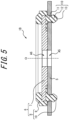
- the stopper 6 is fitted to the bracket 5 (they are temporarily assembled), so as to form the stopper bracket 1B that includes the stopper 6 and the bracket 5, as illustrated in FIG. 5 .
- the stopper bracket 1B can be handled as a single component in which the stopper 6 and bracket 5 are temporarily assembled, before being fastened as the anti-vibration device 1.
- the coating portion 13 can be peeled off by deformation of the positioning protrusion 10, when the bulging portion 12 of the positioning protrusion 10 is pressed so as to be press-fitted into the positioning hole A1. Accordingly, as illustrated in FIG. 4C , after the bulging portion 12 has been prevented from detaching from the bracket 5, the coating portion 13, which functions like a lubricant during the press-fitting, is peeled off from the positioning protrusion 10 due to deformation of the positioning protrusion 10 that occurs during the press-fitting.
- the positioning protrusion 10 is more firmly prevented from detaching from the bracket 5, compared with a case in which a lubricant is applied to the positioning protrusion 10. That is, according to the manufacturing method of the present embodiment, the detaching force required to detach the positioning protrusion 10 is greater than in a case in which a lubricant is applied. Hence, preventing the bulging portion 12 of the positioning protrusion 10 from detaching from the bracket 5 prevents easy separation between the stopper 6 and the bracket 5.
- the second process is a suspension-side fastening process.
- the anti-vibration body 1A is attached to the suspension member 30.
- the anti-vibration body 1A is pressed so as to be press-fitted into the attachment portion 31 of the suspension member 30, as described above. This allows the anti-vibration body 1A to be attached to the suspension member 30 as illustrated in FIG. 1 .
- the third process is a body-side fastening process.
- the anti-vibration body 1A along with the stopper bracket 1B, is attached to the body 40, as illustrated in FIG. 1 .
- the third process includes, for example, aligning the anti-vibration body 1A attached to the suspension member 30 with the positioning portion 41 of the body 40, placing the stopper bracket 1B against a lower end portion of the anti-vibration body 1A (elastic body 4) and passing the bolt shaft 15a through the anti-vibration body 1A, and tightening the bolt 15 so as to fit the anti-vibration device 1, along with the suspension member 30, to the body.
- the stopper 6 can be fitted to the bracket 5 by the following easy work. That is, the coating agent C, which is configured to be peelable after solidification, is applied to the positioning protrusions 10 provided in the stopper 6, and after solidification of the coating agent C, the bulging portions 12 of the positioning protrusions 10 are pressed into the positioning holes A 1 formed in the bracket 5, so as to prevent the bulging portions 12 from detaching from the bracket 5, and thus the stopper 6 can be fitted to the bracket 5. Furthermore, the coating portions 13 are peeled off from the positioning protrusions 10 by deformation of the positioning protrusions 10 that occurs during press-fitting, so that the easy separation between the stopper 6 and the bracket 5 is prevented. Therefore, the bracket 5 and the stopper 6 do not easily separate from each other, even when the bracket 5 and the stopper 6 are handled in a fitted state, as is the case with the stopper bracket 1B.
- the bracket 5 and the stopper 6 can be fastened together so that easy separation between the stopper 6 and the bracket 5 is prevented, while the ease of fastening the stopper 6 and the bracket 5 together is improved.
- the anti-vibration device 1 can be manufactured so that easy separation between the stopper 6 and the bracket 5 is prevented, while the ease of fastening the stopper 6 and the bracket 5 together is improved.
- the anti-vibration device manufacturing method of the present embodiment it is possible to obtain the anti-vibration device in which easy separation between the stopper 6 and the bracket 5 is prevented, while the ease of fastening the stopper 6 and the bracket 5 together is improved.
- the bracket 5 and the stopper 6 can be fastened together so that easy separation between the stopper 6 and the bracket 5 is prevented, while the ease of fastening the stopper 6 and the bracket 5 together is improved.
- the stopper bracket 1B can be manufactured so that the easy separation between the stopper 6 and the bracket 5 is prevented, while the ease of fastening the stopper 6 and the bracket 5 together is improved.
- the coating agent C is a rust inhibitor.
- the coating portions 13 can be formed by applying the rust inhibitor to the positioning protrusions 10, in conjunction with applying an existing rust inhibitor, such as a water-soluble rust inhibitor paint, to the rigid member 7.
- an existing rust inhibitor such as a water-soluble rust inhibitor paint
- the coating agent C is applied to the entire positioning protrusions 10.
- the rust inhibitor portion of the rigid member 7 and the coating portions 13 of the positioning protrusions 10 can be formed all together by a sequence of work.
- the unnecessity of applying the coating agent C separately omits the need for a masking tape or the like. In this case, therefore, the manufacturing method is even more superior in terms of workability and cost-effectiveness.
- the stopper 6 includes the rigid member 7 having the opening A6 formed therein, and the elastic member 8.
- the elastic member 8 includes the stopper body 9 configured to cover the rigid member 7, and the positioning protrusions 10 continuous with the stopper body 9.
- Each positioning protrusion 10 includes the shaft portion 11 extending to one side in the axial direction as part of the stopper body 9 and configured to be able to penetrate through the corresponding positioning hole A5 formed in the bracket 5, the bulging portion 12 continuous with the end of the shaft portion 11 so as to be prevented from detaching from the bracket 5, and the coating portion 13 provided on at least the surface of the bulging portion 12 and configured to be peelable.
- the stopper 6 can be fitted to the bracket 5 by easy work, and the bracket 5 and the stopper 6 do not easily separate from each other, even when they are handled as the stopper bracket 1B, with the positioning protrusions 10 being prevented from detaching from the bracket 5. That is, by using the stopper 6 that is fitted to the bracket 5, easy separation between the stopper 6 and the bracket 5 is prevented, while the ease of fastening the stopper 6 and the bracket 5 together is improved.
- the stopper 6 is therefore suitable for use when manufacturing an anti-vibration device so that easy separation between the stopper and the bracket is prevented, while the ease of fastening the stopper and the bracket together is improved.
- the stopper for an anti-vibration device of the present embodiment it is possible to obtain the anti-vibration device in which easy separation between the stopper and the bracket is prevented, while the ease of fastening the stopper and the bracket together is improved.
- the stopper body 9 is annularly provided, so as to surround the opening A6 formed in the middle of the rigid member 7 in the circumferential direction around the entire circumference.
- the shape of the stopper body 9 can, however, be changed as required.
- the coating portions 13 are formed of a rust inhibitor.
- an existing rust inhibitor such as a water-soluble rust inhibitor paint, can be used, the stopper for an anti-vibration device is superior in terms of manufacturability and cost-effectiveness.
- the coating portions 13 are formed over the entire positioning protrusions 10.
- the stopper for an anti-vibration device is even more superior in terms of manufacturability and cost-effectiveness.
- the ease of fastening the stopper 6 and the bracket 5 together is improved by the positioning protrusions 10 being pressed into the positioning holes A1 via the coating portions 13, while easy separation between the stopper 6 and the bracket 5 is prevented by the coating portions 13 being peeled off from the positioning protrusions 10 by the pressing-in.
- part of each coating portion 13 remains on the corresponding positioning protrusion 10.
- the coating portions 13 can be visible as a marker indicating that the bracket 5 and the stopper 6 will not easily separate from each other, for example, even when they are handled as the stopper bracket 1B, with the positioning protrusions 10 being prevented from detaching from the bracket 5, as described above.
- the coating portions 13 remaining on the positioning protrusions 10 are small in relation to the entire positioning protrusions 10, so that the effect of the partially remaining coating portions 13 functioning as a lubricant is smaller than when a lubricant is applied to the positioning protrusions 10. Accordingly, in the anti-vibration device 1 in which the coating portions 13 partially remain, even in a case in which the bracket 5 and the stopper 6 are disassembled from a state in which the bracket 5 and the stopper 6 are temporarily assembled, and then fastened together, the stopper 6 and the bracket 5 can be easily fastened together.
- the positioning protrusions 10 are more firmly prevented from detaching from the bracket 5 than in a case in which a lubricant is applied to the positioning protrusions 10.
- the stopper for an anti-vibration device of the present embodiment it is possible to obtain the anti-vibration device in which easy separation between the stopper and the bracket is prevented, while the ease of fastening the stopper and the bracket together is improved.
- each coating portion 13 is preferably positioned on the surface of the corresponding bulging portion 12 that is located on one side in the axial direction.
- the surface f2 of a bulging portion 12 is formed by a lower surface f21 and an upper surface f22.
- the axial dimension of the bulging portion 12 is maximum between the lower surface f21 and the upper surface f22.
- the coating portion 13 remains on the lower surface f21.
- the lower surface f21 can shrink inward in the perpendicular-to-axis direction as it extends downward.
- the lower surface f21 is formed by a lower end surface f21a, and a first inclined surface f21b that tapers toward the lower end surface f21a.
- the coating portion 13 may be left on at least one of the lower end surface f21a and the first inclined surface f21b.
- the coating portion 13 is left on the lower end surface f21a of the bulging portion 12.
- the coating portion 13 can be visible, for example, as a decoration on the lower end surface f21a. This can make the coating portion 13 less noticeable.
- the lower end surface f21a can be a point (lower end point) instead of a surface.
- the lower surface f21 can be a dome-shaped surface that projects downward.
- the upper surface f22 can expand outward in the axial direction as it extends downward.
- the upper surface f22 is formed by a second inclined surface that that widens downward.
- the upper surface f22 can extend to the outer side in the perpendicular-to-axis direction in parallel to the perpendicular-to-axis direction. In this case, the upper surface f22 can be hidden behind the lower surface f21 by coming into surface contact with the bracket 5.
- the coating portion 13 remains on the lower surface f21 of the bulging portion 12 that first contacts against the bracket 5 when the positioning protrusion 10 is pressed in, so that the positioning protrusion 10 can be pressed in smoothly against the positioning hole A1. Furthermore, because the coating portion 13 does not remain on any surface other than the lower surface f21 of the bulging portion 12, the positioning protrusion 10 is more firmly prevented from detaching from the bracket 5. Thus, by having the coating portion 13 remain on the lower surface f21 of the bulging portion 12, easy separation between the stopper 6 and the bracket 5 is even more prevented, while the ease of fastening the stopper 6 and the bracket 5 together is improved.
- the coating portions 13 are formed of a rust inhibitor.
- the anti-vibration device is superior in terms of manufacturability and cost-effectiveness.
- each coating portion 13 is located on the lower surface f21 of the corresponding bulging portion 12. In this case, easy separation between the stopper 6 and the bracket 5 is even more prevented, while the ease of fastening the stopper 6 and the bracket 5 together is improved.
- the anti-vibration device 1 is fitted to the vehicle body 40 with the bolt 15, but the method of fitting the anti-vibration device 1 to the body 40 is not limited to this.
- the anti-vibration device 1 can be fitted to the body 40, for example, by passing a threaded shaft provided in the body 40 through the through hole A2 and using a nut threaded onto the threaded shaft.
- the anti-vibration device 1 is not limited to the one formed by fitting one end of the anti-vibration device 1 in the axial direction to the body 40 through the bolt 15.
- the anti-vibration device 1 can be configured separately from the body 40, by replacing the body 40 with another bracket.
Landscapes
- Engineering & Computer Science (AREA)
- General Engineering & Computer Science (AREA)
- Mechanical Engineering (AREA)
- Physics & Mathematics (AREA)
- Chemical & Material Sciences (AREA)
- Combustion & Propulsion (AREA)
- Acoustics & Sound (AREA)
- Aviation & Aerospace Engineering (AREA)
- Manufacturing & Machinery (AREA)
- Health & Medical Sciences (AREA)
- Child & Adolescent Psychology (AREA)
- Springs (AREA)
- Vibration Prevention Devices (AREA)
- Vehicle Body Suspensions (AREA)
- Combined Devices Of Dampers And Springs (AREA)
Applications Claiming Priority (2)
| Application Number | Priority Date | Filing Date | Title |
|---|---|---|---|
| JP2020196350A JP7487080B2 (ja) | 2020-11-26 | 2020-11-26 | 防振装置の製造方法、防振装置のストッパ及び防振装置 |
| PCT/JP2021/032900 WO2022113467A1 (ja) | 2020-11-26 | 2021-09-07 | 防振装置の製造方法、防振装置のストッパ及び防振装置 |
Publications (2)
| Publication Number | Publication Date |
|---|---|
| EP4253103A1 true EP4253103A1 (de) | 2023-10-04 |
| EP4253103A4 EP4253103A4 (de) | 2024-10-30 |
Family
ID=81754495
Family Applications (1)
| Application Number | Title | Priority Date | Filing Date |
|---|---|---|---|
| EP21897445.9A Pending EP4253103A4 (de) | 2020-11-26 | 2021-09-07 | Herstellungsverfahren für eine schwingungsdämpfende vorrichtung, stopper für eine schwingungsdämpfende vorrichtung und schwingungsdämpfende vorrichtung |
Country Status (5)
| Country | Link |
|---|---|
| US (1) | US12473960B2 (de) |
| EP (1) | EP4253103A4 (de) |
| JP (1) | JP7487080B2 (de) |
| CN (1) | CN116568531B (de) |
| WO (1) | WO2022113467A1 (de) |
Families Citing this family (3)
| Publication number | Priority date | Publication date | Assignee | Title |
|---|---|---|---|---|
| KR102598914B1 (ko) * | 2021-09-28 | 2023-11-03 | 컨템포러리 엠퍼렉스 테크놀로지 씨오., 리미티드 | 유동 너트 조립체 및 전기기기 |
| FR3148063A1 (fr) * | 2023-04-21 | 2024-10-25 | Airbus Operations | Ensemble pour la fixation de poutres comportant une plaque support et deux ferrures de part et d’autre de la plaque support |
| KR20250051304A (ko) * | 2023-10-10 | 2025-04-17 | 현대자동차주식회사 | 부시 |
Family Cites Families (13)
| Publication number | Priority date | Publication date | Assignee | Title |
|---|---|---|---|---|
| JPS6132809U (ja) * | 1984-07-31 | 1986-02-27 | 豊田合成株式会社 | 合成樹脂製クリツプ |
| JPH0425013U (de) * | 1990-06-26 | 1992-02-28 | ||
| JP2574609Y2 (ja) * | 1991-11-22 | 1998-06-18 | 株式会社ニフコ | クリップ |
| JP2001245427A (ja) | 2000-02-29 | 2001-09-07 | Yazaki Corp | ハーネス取付クリップ |
| JP2001270402A (ja) * | 2000-03-27 | 2001-10-02 | Piolax Inc | 車体パネル用クリップ |
| JP2003097629A (ja) * | 2001-09-21 | 2003-04-03 | Toyo Tire & Rubber Co Ltd | 防振マウント |
| JP4103763B2 (ja) | 2003-10-17 | 2008-06-18 | 東海ゴム工業株式会社 | 防振マウントのゴムストッパの組付構造及び組付方法 |
| CN201059312Y (zh) * | 2007-07-10 | 2008-05-14 | 华为技术有限公司 | 止退装置和插件助力扳手 |
| US8561265B2 (en) * | 2011-04-12 | 2013-10-22 | Newfrey Llc | Interior trim fastener |
| FR3026446B1 (fr) * | 2014-09-30 | 2017-12-01 | Lisi Aerospace | Fixation en interference lubrifiee |
| JP6602956B2 (ja) * | 2015-08-25 | 2019-11-06 | ヘラマンタイトン コーポレイション | 止まり穴マウント |
| KR102087955B1 (ko) * | 2018-11-16 | 2020-03-12 | 현대트랜시스 주식회사 | 자동차용 시트의 백보드 체결 장치 |
| JP7264708B2 (ja) * | 2019-04-17 | 2023-04-25 | 株式会社プロスパイラ | ストッパ部材 |
-
2020
- 2020-11-26 JP JP2020196350A patent/JP7487080B2/ja active Active
-
2021
- 2021-09-07 US US18/254,656 patent/US12473960B2/en active Active
- 2021-09-07 EP EP21897445.9A patent/EP4253103A4/de active Pending
- 2021-09-07 CN CN202180079580.6A patent/CN116568531B/zh active Active
- 2021-09-07 WO PCT/JP2021/032900 patent/WO2022113467A1/ja not_active Ceased
Also Published As
| Publication number | Publication date |
|---|---|
| JP2022084451A (ja) | 2022-06-07 |
| JP7487080B2 (ja) | 2024-05-20 |
| EP4253103A4 (de) | 2024-10-30 |
| CN116568531A (zh) | 2023-08-08 |
| US12473960B2 (en) | 2025-11-18 |
| CN116568531B (zh) | 2026-01-09 |
| US20240011539A1 (en) | 2024-01-11 |
| WO2022113467A1 (ja) | 2022-06-02 |
Similar Documents
| Publication | Publication Date | Title |
|---|---|---|
| US12473960B2 (en) | Antivibration device production method, stopper for antivibration device, and antivibration device | |
| US7306418B2 (en) | Deforming member and captive fastener retaining method | |
| EP1118778A1 (de) | Mit Gewinde versehenes Befestigungselement und entsprechendes Befestigungssystem | |
| US8747040B2 (en) | Screw assembly element | |
| EP0524750A1 (de) | Unverlierbares Befestigungselement und Verfahren zu dessen Einbau | |
| US11077538B2 (en) | Torque retaining apparatus and method of production | |
| BR0309205A (pt) | Elemento funcional para a fixação em uma parte de chapa de metal, componente de montagem, e, processo para a fixação de um elemento funcional | |
| WO1995011403A1 (en) | Clamping collar | |
| US20040148759A1 (en) | Function element assembly part consisting of a sheet metal part and a function element and method for attaching a function element to a sheet metal part | |
| JPH08281660A (ja) | 樹脂成形金型におけるインサート部品の位置決め構造 | |
| US12163549B2 (en) | Hinged retainer assembly | |
| JPH05180350A (ja) | 等速自在継手用ブーツの締付け構造および方法 | |
| JPH0642561A (ja) | ディスクブレーキ | |
| JPH10278502A (ja) | 自動車用ホイールの製造方法及び自動車用ホイール | |
| JP2005291278A (ja) | 電食防止ボルトおよび車両用ブレーキ装置 | |
| KR20220047606A (ko) | 압축 제한기 견부를 구비한 리벳 너트 | |
| JPH06210218A (ja) | マスキング部材 | |
| JPH09141377A (ja) | アルミニウム合金板のリベット締結構造 | |
| JP2019113111A (ja) | 部材締結構造 | |
| JP2566707Y2 (ja) | 植設ボルト用マスキング治具 | |
| JP2002317852A (ja) | 基体取付装置、及び該基体取付装置を備えた車両用液圧ユニット、並びに基体取付方法 | |
| JP2003278835A (ja) | ラジエータサポート | |
| JP4293769B2 (ja) | ブレーキパイプ及び口金具 | |
| JP2527908Y2 (ja) | 抜取り治具 | |
| JP2543285Y2 (ja) | スキーストック |
Legal Events
| Date | Code | Title | Description |
|---|---|---|---|
| STAA | Information on the status of an ep patent application or granted ep patent |
Free format text: STATUS: THE INTERNATIONAL PUBLICATION HAS BEEN MADE |
|
| PUAI | Public reference made under article 153(3) epc to a published international application that has entered the european phase |
Free format text: ORIGINAL CODE: 0009012 |
|
| STAA | Information on the status of an ep patent application or granted ep patent |
Free format text: STATUS: REQUEST FOR EXAMINATION WAS MADE |
|
| 17P | Request for examination filed |
Effective date: 20230531 |
|
| AK | Designated contracting states |
Kind code of ref document: A1 Designated state(s): AL AT BE BG CH CY CZ DE DK EE ES FI FR GB GR HR HU IE IS IT LI LT LU LV MC MK MT NL NO PL PT RO RS SE SI SK SM TR |
|
| DAV | Request for validation of the european patent (deleted) | ||
| DAX | Request for extension of the european patent (deleted) | ||
| REG | Reference to a national code |
Ref country code: DE Ref legal event code: R079 Free format text: PREVIOUS MAIN CLASS: B60G0007020000 Ipc: F16F0001380000 |
|
| A4 | Supplementary search report drawn up and despatched |
Effective date: 20240927 |
|
| RIC1 | Information provided on ipc code assigned before grant |
Ipc: B60G 7/02 20060101ALI20240923BHEP Ipc: F16B 9/00 20060101ALI20240923BHEP Ipc: F16B 4/00 20060101ALI20240923BHEP Ipc: F16B 2/22 20060101ALI20240923BHEP Ipc: F16B 21/08 20060101ALI20240923BHEP Ipc: F16F 1/38 20060101AFI20240923BHEP |