EP4261500A1 - Vermessungsinstrument - Google Patents
Vermessungsinstrument Download PDFInfo
- Publication number
- EP4261500A1 EP4261500A1 EP23164571.4A EP23164571A EP4261500A1 EP 4261500 A1 EP4261500 A1 EP 4261500A1 EP 23164571 A EP23164571 A EP 23164571A EP 4261500 A1 EP4261500 A1 EP 4261500A1
- Authority
- EP
- European Patent Office
- Prior art keywords
- light
- measuring
- distance
- surveying instrument
- instrument
- Prior art date
- Legal status (The legal status is an assumption and is not a legal conclusion. Google has not performed a legal analysis and makes no representation as to the accuracy of the status listed.)
- Granted
Links
Images


Classifications
-
- G—PHYSICS
- G01—MEASURING; TESTING
- G01C—MEASURING DISTANCES, LEVELS OR BEARINGS; SURVEYING; NAVIGATION; GYROSCOPIC INSTRUMENTS; PHOTOGRAMMETRY OR VIDEOGRAMMETRY
- G01C15/00—Surveying instruments or accessories not provided for in groups G01C1/00 - G01C13/00
- G01C15/002—Active optical surveying means
- G01C15/004—Reference lines, planes or sectors
- G01C15/006—Detectors therefor
-
- G—PHYSICS
- G01—MEASURING; TESTING
- G01C—MEASURING DISTANCES, LEVELS OR BEARINGS; SURVEYING; NAVIGATION; GYROSCOPIC INSTRUMENTS; PHOTOGRAMMETRY OR VIDEOGRAMMETRY
- G01C15/00—Surveying instruments or accessories not provided for in groups G01C1/00 - G01C13/00
- G01C15/10—Plumb lines
- G01C15/105—Optical plumbing
-
- G—PHYSICS
- G01—MEASURING; TESTING
- G01B—MEASURING LENGTH, THICKNESS OR SIMILAR LINEAR DIMENSIONS; MEASURING ANGLES; MEASURING AREAS; MEASURING IRREGULARITIES OF SURFACES OR CONTOURS
- G01B11/00—Measuring arrangements characterised by the use of optical techniques
- G01B11/02—Measuring arrangements characterised by the use of optical techniques for measuring length, width or thickness
- G01B11/06—Measuring arrangements characterised by the use of optical techniques for measuring length, width or thickness for measuring thickness ; e.g. of sheet material
- G01B11/0608—Height gauges
-
- G—PHYSICS
- G01—MEASURING; TESTING
- G01C—MEASURING DISTANCES, LEVELS OR BEARINGS; SURVEYING; NAVIGATION; GYROSCOPIC INSTRUMENTS; PHOTOGRAMMETRY OR VIDEOGRAMMETRY
- G01C3/00—Measuring distances in line of sight; Optical rangefinders
- G01C3/02—Details
-
- G—PHYSICS
- G01—MEASURING; TESTING
- G01S—RADIO DIRECTION-FINDING; RADIO NAVIGATION; DETERMINING DISTANCE OR VELOCITY BY USE OF RADIO WAVES; LOCATING OR PRESENCE-DETECTING BY USE OF THE REFLECTION OR RERADIATION OF RADIO WAVES; ANALOGOUS ARRANGEMENTS USING OTHER WAVES
- G01S17/00—Systems using the reflection or reradiation of electromagnetic waves other than radio waves, e.g. lidar systems
- G01S17/02—Systems using the reflection of electromagnetic waves other than radio waves
- G01S17/06—Systems determining position data of a target
- G01S17/42—Simultaneous measurement of distance and other co-ordinates
-
- G—PHYSICS
- G01—MEASURING; TESTING
- G01S—RADIO DIRECTION-FINDING; RADIO NAVIGATION; DETERMINING DISTANCE OR VELOCITY BY USE OF RADIO WAVES; LOCATING OR PRESENCE-DETECTING BY USE OF THE REFLECTION OR RERADIATION OF RADIO WAVES; ANALOGOUS ARRANGEMENTS USING OTHER WAVES
- G01S7/00—Details of systems according to groups G01S13/00, G01S15/00, G01S17/00
- G01S7/48—Details of systems according to groups G01S13/00, G01S15/00, G01S17/00 of systems according to group G01S17/00
- G01S7/497—Means for monitoring or calibrating
Definitions
- the present invention relates to a surveying instrument equipped with an instrument height measuring unit that makes a distance measurement and calculates an instrument height.
- a surveying instrument main body is disposed horizontally at a position vertically above a reference point through a leveling work and a centering work, and then, an instrument height that is a height from an optical center of the surveying instrument main body to the reference point vertically below the optical center is obtained.
- a surveying instrument that includes a distance-measuring device for measuring the instrument height as an instrument height measuring unit, and makes a measurement by emitting distance-measuring light toward a position vertically below the surveying instrument main body and automatically calculates the instrument height.
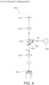
- FIG. 4 is an optical configuration diagram of the conventional distance-measuring device 940.
- the distance-measuring device 940 includes a light transmitting unit 951, a collimating lens 952, a beam splitter 954 that is a dichroic prism, a light receiving unit 955, a shutter 956, and an objective lens 957.
- Light emitted from the light transmitting unit 951 is collimated into parallel light by the collimating lens 952, made incident on the beam splitter 954 and split into distance-measuring light L2 and reference light R2, and alternatively emitted by the shutter 956.
- the reference light R2 is directed toward and received by the light receiving unit 955, and the distance-measuring light L2 passes through the objective lens 957 and is emitted toward a position below a vertical axis of the surveying instrument main body, and returns by being reflected by a measuring mark 902 that is a distance-measuring object and a reference point, and is received by the light receiving unit 955. From a difference between light reception signals of the reference light R2 and the distance-measuring light L2, a distance to the object is calculated.
- the alternative emission of the distance-measuring light L2 and the reference light R2 by the shutter 956 is performed by movements of a switching plate (for example, Patent Literature 1) .
- the switching plate is moved by a driving unit to block one of the two light paths through which the lights are emitted and allow passage through the other path, by which the light path of emitted light is alternatively switched between a reference light path and a distance-measuring light path.
- Patent Literature 1 Japanese Published Unexamined Patent Application No. 2008-232881
- the shutter is not an electronic component or the like but a movable switching plate, and a driving unit for moving the switching plate is also required, so that the distance-measuring device including the shutter is comparatively large in size. Because it is incorporated in the surveying instrument main body, it is desirable that the instrument height measuring unit as the distance-measuring device is compact in size.
- the present invention was made in view of this, and provides a surveying instrument equipped with an instrument height measuring unit compact in size.
- a surveying instrument including an instrument height measuring unit configured to make a distance measurement by irradiating light toward a position below a vertical axis of a surveying instrument main body and calculate an instrument height
- the instrument height measuring unit includes a light transmitting unit configured to emit light, a beam splitter configured to be incident with light emitted from the light transmitting unit, split the incident light into reference light and distance-measuring light, send the reference light to a reference light path, and send the distance-measuring light to a distance-measuring light path, a first light receiving unit configured to receive the reference light, a second light receiving unit configured to receive light being the distance-measuring light that has been emitted toward a position below the vertical axis of the surveying instrument main body and returned by being reflected by a distance-measuring object, and an arithmetic unit configured to calculate the instrument height based on light reception signals generated by the first light receiving
- two light receiving units are used, and reference light is received by the first light receiving unit, and distance-measuring light is received by the second light receiving unit, and the reference light path and the distance-measuring light path are different from each other, so that alternatively switching between the reference light path and the distance-measuring light path by using the shutter is no longer necessary.
- the shutter and the driving unit for driving the shutter become unnecessary, so that the instrument height measuring unit can be made more compact in size than a conventional one.
- the conventional technology has a problem in which a distance measurement cannot be performed during switching of the light paths by the shutter, however, by using the two light receiving units, the time for switching light paths is eliminated, and measurement results can be successively output.
- the distance-measuring device using light employs the Time-of-Flight method (ToF method) in which a distance is calculated by using a difference between a time until reference light is received and a time until distance-measuring light is received, and the Time-of-Flight method includes a Direct ToF method (dToF method) in which a difference in time until detection of reflected light is simply measured, and an Indirect ToF method (iTOF method) in which a distance is calculated from a phase difference.
- the iToF method is preferable, however, in the instrument height measuring unit configured as described above, no shutter is used, so that either the dToF method or the iToF method can be used.
- a configuration is provided such that the light emitted by the light transmitting unit is visible laser light, and the distance-measuring light is irradiated as a laser centering point toward a position below the vertical axis of the surveying instrument main body.
- visible light irradiated vertically downward can be used as a laser centering point, and a centering work can be performed with reference to the laser centering point as a guide.
- a configuration is provided such that light receiving elements of the first light receiving unit and the second light receiving unit have temperature characteristics that are equivalent to each other.
- Optical elements used as the light receiving units have temperature characteristics, that is, temperature change characteristics of photoelectric conversion time, and the temperature characteristics differ depending on each of the optical elements.
- filtering is applied by using an application and/or a component for making a light emission amount variable, however, this increases the number of components, and also increases the size of the distance-measuring device.
- signal processing is performed by using light receiving elements having equivalent temperature characteristics to each other for each of the light receiving units, so that a circuit scale can be made smaller.
- a surveying instrument equipped with an instrument height measuring unit compact in size can be provided.
- FIG. 1 is a perspective view of a surveying instrument 1 and a measuring mark 2 according to a preferred embodiment of the present invention.
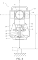
- FIG. 2 is an explanatory view illustrating a schematic configuration of the surveying instrument 1 and the measuring mark 2.
- FIG. 2 is a partially cut-away view.
- the surveying instrument 1 is a total station having distance-measuring and angle-measuring functions.
- the measuring mark 2 is a survey reference point, and is provided on the point of a stone marker 3.
- the surveying instrument 1 includes a main body casing 12 as a housing of the surveying instrument.
- the main body casing 12 corresponds to the surveying instrument main body in Claims of the present application.
- the main body casing 12 includes two supporting posts 14, and between the two supporting posts 14, a collimating telescope 16 is axially supported turnably around a horizontal axis H.
- a display 20 and an operation key group 21 are disposed on a lower portion of the main body casing 12.
- the display 20 displays necessary information on a screen.
- the operation key group 21 is input means for inputting necessary setting conditions and commands.
- the main body casing 12 is disposed on a leveling base 25, and the leveling base 25 is fixed to a tripod 8 in a state where the leveling base 25 is placed on the tripod 8 .
- a shaft cylinder 26 is disposed on a fixation portion 24 at a lower portion of the main body casing 12. Inside the shaft cylinder 26, a vertical shaft 28 provided vertically in the main body casing 12 is inserted, and axially supported turnably on the fixation portion 24 via a ball bearing. Accordingly, the main body casing 12 is turnable around the vertical shaft 28 with respect to the fixation portion 24.
- the leveling base 25 has an adjust screw for finely adjusting a tilt, and the fixation portion 24 is fixed onto the adjust screw. By turning of the adjust screw, the surveying instrument 1 is adjusted to be horizontal.
- the rotary encoder 22 is a horizontal angle sensor, and detects a rotation amount of the main body casing 12.
- the vertical shaft 28 is formed into a hollow cylindrical shape, and an extension of a centerline V of the vertical shaft 28 intersects the horizontal axis H orthogonally.
- the orthogonal intersection point between the horizontal axis H and the centerline V is set as a center point O of the surveying instrument 1. Since the main body casing 12 axially supporting the collimating telescope 16 turns around the centerline V, by an angle sensor 18 provided on the horizontal axis H and the rotary encoder 22 described above, a rotation amount of the collimating telescope 16 around the horizontal axis H and a rotation amount around the centerline V are detected. That is, the centerline V is a vertical axis of the surveying instrument main body.
- the instrument height measuring unit 40 is a non-prism electro-optical distance measuring device which emits distance-measuring light L to a distance-measuring object, and analyzes reflected and returned light to measure a distance to the distance-measuring object.
- An optical axis of the instrument height measuring unit 40 is configured to match the centerline V, and the distance-measuring light L emitted from the instrument height measuring unit 40 passes through a hollow portion of the vertical shaft 28 and is emitted downward from a bottom surface of the surveying instrument 1.
- FIG. 3 is a configuration diagram of an optical system of the instrument height measuring unit 40.
- the instrument height measuring unit 40 includes a light transmitting unit 51, a collimating lens 52, a beam splitter 53, a first light receiving unit 54, a half mirror 55, an objective lens 56, and a second light receiving unit 57.
- the light transmitting unit 51 is a light source that emits visible laser light, and consists of a laser diode (LD).
- the collimating lens 52 is disposed in front of the light transmitting unit 51, and light emitted from the light transmitting unit 51 is collimated into parallel light by the collimating lens 52.
- An optical axis of the collimating lens 52 is configured to match the centerline V and so that the optical axis line passes through the center point O of the surveying instrument 1.
- the beam splitter 53, the half mirror 55, and the objective lens 56 are disposed in order on the optical axis of the collimating lens 52.
- the beam splitter 53 is an optical member that consists of a dichroic prism, and splits light by reflecting a portion of incident light and causing the remaining portion to pass through.
- the light that has been emitted from the collimating lens 52 is made incident on the beam splitter 53 and split into reference light R and distance-measuring light L.
- the reference light R is sent to a reference light path leading to the first light receiving unit 54 and received by the first light receiving unit 54.
- the distance-measuring light L is sent to a distance-measuring light path through which light passes as it is and travels toward the half mirror 55.
- the distance-measuring light L that has traveled toward the half mirror 55 passes through the half mirror 55 as it is, travels toward the objective lens 56, passes through the same, and is emitted toward a position below the vertical axis of the surveying instrument main body. Then, the distance-measuring light L is reflected by a distance-measuring object (in the present embodiment, a measuring mark 2) below the surveying instrument 1 and returns to the surveying instrument 1 following the same course, and is then reflected by the half mirror 55 and travels toward the second light receiving unit 57, and is received by the second light receiving unit 57.
- a distance-measuring object in the present embodiment, a measuring mark 2
- the instrument height measuring unit 40 includes an arithmetic unit 90.
- the first light receiving unit 54 and the second light receiving unit 57 consist of Avalanche photodiodes (APDs), and light reception signals generated by the first light receiving unit 54 and the second light receiving unit 57 are output to the arithmetic unit 90 (refer to FIG. 2 ) .
- the arithmetic unit 90 is a microcomputer including a memory and a CPU. An analysis program is stored in the memory. The arithmetic unit 90 analyzes light reception signals generated by the first light receiving unit 54 and the second light receiving unit 57, and obtains a distance to the measuring mark 2 from a difference between the light reception signals.
- a disposition relationship between the center point O of the surveying instrument 1 and the optical members of the instrument height measuring unit 40 (particularly a light transmission point of the light transmitting unit 51) is grasped, and by adding a height from the center point O to the instrument height measuring unit 40 to a distance measurement result, an instrument height T is calculated.
- the calculated instrument height T is displayed on the display 20.
- a distance calculation method of the instrument height measuring unit 40 as a distance-measuring device using two photoreceptors including the first light receiving unit 54 and the second light receiving unit 57 will be described.
- the following arithmetic operations are performed by the arithmetic unit 90.
- Optical path 1 Reference light path
- Optical path 2 Distance-measuring light path
- a distance D to be measured by the instrument height measuring unit 40 is as follows.
- ⁇ T Light reception time difference between first light receiving unit and second light receiving unit
- ⁇ T in the case of the known distance is calculated.
- This ⁇ T is stored as TReference in the memory of the arithmetic unit 90.
- the light receiving elements of the first light receiving unit 54 and the second light receiving unit 57 have characteristics that are equivalent to each other.
- a photoelectric conversion time of an optical element has temperature characteristics, and the temperature characteristics differ depending on the light receiving element, however, by using light receiving units having temperature characteristics that are equivalent to each other, this difference is canceled, and a distance measurement can be performed with high accuracy.
- the same products are preferably used, and the same products with the same model numbers are more preferably used. Further, this makes filtering and signal processing circuits unnecessary, so that the circuit scale can be made smaller.
- either the dToF method or the iToF method may be used.
- TDC Time to Digital Converter
- signal processing can be performed in a smaller circuit scale and at a comparatively low cost.
- light to be emitted by the light transmitting unit 51 is visible light
- distance-measuring light L irradiated toward a position below the surveying instrument 1 is also used as centering laser light. That is, the optical axis of the collimating lens 52 matches the centerline V of the vertical shaft 28, and the distance-measuring light L is emitted downward from the bottom surface of the surveying instrument 1, so that the distance-measuring light L irradiated toward a measuring object below the surveying instrument 1 is visually recognized as a laser centering point that serves as a guide below the vertical axis of the surveying instrument main body passing through the center point O.
- the surveying instrument 1 can be disposed along a vertical axis of the measuring mark 2.
- the worker When a worker installs the surveying instrument 1 by using the measuring mark 2 as a reference point, the worker places the surveying instrument 1 substantially vertically above the measuring mark 2 by means of the tripod 8, and performs a leveling work to level the surveying instrument 1 by using the adjust screw of the leveling base 25. Then, a portion of light emitted from the light transmitting unit 51 is irradiated as distance-measuring light L toward the measuring mark 2, so that while maintaining a leveled state, the worker performs a positional adjustment by sliding the surveying instrument 1 so that the center of the measuring mark 2 matches a center of the distance-measuring light L irradiated toward the measuring mark 2.
- This centering work may cause the surveying instrument 1 to tilt from the horizontal state, and by repeating the leveling work and the centering work, the worker horizontally places the surveying instrument 1 vertically above the measuring mark 2.
- the instrument height measuring unit 40 does not include a shutter and thus does not require switching of light paths, and can also successively calculate measurement values, so that at the time of the centering work, calculation of an instrument height T is also performed.
- the switching work is not required, and the centering work and the instrument height measuring work can be performed in parallel, so that the work to install the surveying instrument 1 can be efficiently performed.
- the instrument height measuring unit 40 has not only the instrument height measuring function but also a centering laser light irradiating function for the centering work.
- the instrument height measuring unit 40 may have only the instrument height measuring function, and may be configured so as to perform the centering work separately.
- a conventional configuration for example, a configuration including a centering telescope, can be used without problem.
- the instrument height measuring unit 40 is disposed above the vertical shaft 28, and its optical members are also all disposed above the vertical shaft 28.
- some of the optical members of the instrument height measuring unit 40 may be disposed on the vertical shaft 28, the fixation portion 24, and the like, such as a configuration in which the light transmitting unit 51 is attached to the main body casing 12, and the collimating lens 52 and the objective lens 56 are disposed inside the hollow vertical shaft 28.
Landscapes
- Physics & Mathematics (AREA)
- Engineering & Computer Science (AREA)
- General Physics & Mathematics (AREA)
- Radar, Positioning & Navigation (AREA)
- Remote Sensing (AREA)
- Electromagnetism (AREA)
- Computer Networks & Wireless Communication (AREA)
- Optical Radar Systems And Details Thereof (AREA)
- Length Measuring Devices By Optical Means (AREA)
- Measurement Of Optical Distance (AREA)
Applications Claiming Priority (1)
| Application Number | Priority Date | Filing Date | Title |
|---|---|---|---|
| JP2022057725A JP2023149250A (ja) | 2022-03-30 | 2022-03-30 | 測量機 |
Publications (2)
| Publication Number | Publication Date |
|---|---|
| EP4261500A1 true EP4261500A1 (de) | 2023-10-18 |
| EP4261500B1 EP4261500B1 (de) | 2026-04-29 |
Family
ID=85778919
Family Applications (1)
| Application Number | Title | Priority Date | Filing Date |
|---|---|---|---|
| EP23164571.4A Active EP4261500B1 (de) | 2022-03-30 | 2023-03-28 | Vermessungsinstrument |
Country Status (4)
| Country | Link |
|---|---|
| US (1) | US12571631B2 (de) |
| EP (1) | EP4261500B1 (de) |
| JP (1) | JP2023149250A (de) |
| CN (1) | CN116892915A (de) |
Families Citing this family (2)
| Publication number | Priority date | Publication date | Assignee | Title |
|---|---|---|---|---|
| JP2023149252A (ja) | 2022-03-30 | 2023-10-13 | 株式会社トプコン | 測量機 |
| JP2023149251A (ja) | 2022-03-30 | 2023-10-13 | 株式会社トプコン | 測量機 |
Citations (3)
| Publication number | Priority date | Publication date | Assignee | Title |
|---|---|---|---|---|
| JP2008232881A (ja) | 2007-03-22 | 2008-10-02 | Sokkia Topcon Co Ltd | 光波距離計 |
| CN205067877U (zh) * | 2015-09-18 | 2016-03-02 | 王治霞 | 分光片及其激光共轴测距仪 |
| US20200166340A1 (en) * | 2018-11-28 | 2020-05-28 | Hexagon Technology Center Gmbh | Intelligent positioning module |
Family Cites Families (37)
| Publication number | Priority date | Publication date | Assignee | Title |
|---|---|---|---|---|
| US4056311A (en) | 1973-08-16 | 1977-11-01 | American Optical Corporation | Progressive power ophthalmic lens having a plurality of viewing zones with non-discontinuous variations therebetween |
| US5291262A (en) | 1989-03-27 | 1994-03-01 | Dunne Jeremy G | Laser surveying instrument |
| JP2651881B2 (ja) | 1991-09-07 | 1997-09-10 | オリベスト株式会社 | 硫化物の除去装置 |
| JPH06213664A (ja) | 1993-01-19 | 1994-08-05 | Topcon Corp | 測量機の求心装置 |
| JP3781866B2 (ja) * | 1997-06-12 | 2006-05-31 | 株式会社ソキア | 求心装置 |
| JP3794599B2 (ja) | 1997-07-31 | 2006-07-05 | 株式会社トプコン | 光軸補償装置 |
| JP4177784B2 (ja) | 2004-05-14 | 2008-11-05 | 株式会社 ソキア・トプコン | 測量システム |
| JP2008008836A (ja) * | 2006-06-30 | 2008-01-17 | Sunx Ltd | 距離測定装置 |
| JP5057734B2 (ja) | 2006-09-25 | 2012-10-24 | 株式会社トプコン | 測量方法及び測量システム及び測量データ処理プログラム |
| US9858712B2 (en) | 2007-04-09 | 2018-01-02 | Sam Stathis | System and method capable of navigating and/or mapping any multi-dimensional space |
| JP5060358B2 (ja) | 2008-03-25 | 2012-10-31 | 株式会社トプコン | 測量システム |
| JP5683782B2 (ja) * | 2008-12-25 | 2015-03-11 | 株式会社トプコン | 距離測定装置及び距離測定方法 |
| JP5349997B2 (ja) * | 2009-02-10 | 2013-11-20 | 株式会社ケネック | 光学式変位計 |
| US10466050B2 (en) | 2014-06-06 | 2019-11-05 | Carlson Software, Inc. | Hybrid total station with electronic leveling |
| US11662470B2 (en) | 2014-06-06 | 2023-05-30 | Carlson Software, Inc. | Survey range pole and data collector with electronic height detection, leveling and hands-free data collection |
| JP6436695B2 (ja) | 2014-09-17 | 2018-12-12 | 株式会社トプコン | 測量装置及び測量装置の設置方法 |
| JP6456149B2 (ja) | 2015-01-13 | 2019-01-23 | 株式会社トプコン | 測量機器 |
| JP6560596B2 (ja) | 2015-11-18 | 2019-08-14 | 株式会社トプコン | 測量装置 |
| JP6680553B2 (ja) | 2016-02-08 | 2020-04-15 | 株式会社トプコン | 測量装置 |
| US10018726B2 (en) | 2016-03-19 | 2018-07-10 | Velodyne Lidar, Inc. | Integrated illumination and detection for LIDAR based 3-D imaging |
| EP3264034B1 (de) * | 2016-06-30 | 2020-02-26 | Leica Geosystems AG | Vermessungsgerät mit höhenmesssystem und verfahren zum messen einer höhe |
| JP6749192B2 (ja) * | 2016-09-21 | 2020-09-02 | 株式会社トプコン | スキャナ装置および測量装置 |
| US10949579B2 (en) | 2017-02-22 | 2021-03-16 | Middle Chart, LLC | Method and apparatus for enhanced position and orientation determination |
| JP6841726B2 (ja) | 2017-06-08 | 2021-03-10 | 株式会社トプコン | 位相差周波数作成方法及び位相差周波数作成装置及び光波距離計 |
| JP7084705B2 (ja) * | 2017-09-13 | 2022-06-15 | 株式会社トプコン | 測量装置 |
| JP2019078631A (ja) | 2017-10-24 | 2019-05-23 | シャープ株式会社 | パルス光照射受光装置、および光レーダー装置 |
| JP6864653B2 (ja) | 2018-06-21 | 2021-04-28 | 株式会社トプコン | 鉛直測定システム及び基準点のトレース方法 |
| JP7202261B2 (ja) | 2019-06-10 | 2023-01-11 | 株式会社トプコン | 測量装置 |
| JP7303671B2 (ja) * | 2019-06-18 | 2023-07-05 | 株式会社東芝 | 電子装置及び距離計測方法 |
| JP7360298B2 (ja) * | 2019-10-23 | 2023-10-12 | 株式会社トプコン | 測量装置 |
| JP7416647B2 (ja) * | 2020-03-12 | 2024-01-17 | 株式会社トプコン | 測量装置 |
| JP2021167736A (ja) | 2020-04-09 | 2021-10-21 | 株式会社トプコン | 傾斜センサおよびデータ取得装置 |
| US11520166B2 (en) | 2020-09-24 | 2022-12-06 | Johnson & Johnson Vision Care, Inc. | Cosmetic contact lens with reversible effects |
| JP2023127741A (ja) * | 2022-03-02 | 2023-09-14 | 株式会社トプコン | 測量装置 |
| JP7813609B2 (ja) * | 2022-03-02 | 2026-02-13 | 株式会社トプコン | 測量装置 |
| JP2023149251A (ja) * | 2022-03-30 | 2023-10-13 | 株式会社トプコン | 測量機 |
| JP2023149252A (ja) * | 2022-03-30 | 2023-10-13 | 株式会社トプコン | 測量機 |
-
2022
- 2022-03-30 JP JP2022057725A patent/JP2023149250A/ja active Pending
-
2023
- 2023-03-23 US US18/125,591 patent/US12571631B2/en active Active
- 2023-03-28 EP EP23164571.4A patent/EP4261500B1/de active Active
- 2023-03-30 CN CN202310324588.5A patent/CN116892915A/zh active Pending
Patent Citations (3)
| Publication number | Priority date | Publication date | Assignee | Title |
|---|---|---|---|---|
| JP2008232881A (ja) | 2007-03-22 | 2008-10-02 | Sokkia Topcon Co Ltd | 光波距離計 |
| CN205067877U (zh) * | 2015-09-18 | 2016-03-02 | 王治霞 | 分光片及其激光共轴测距仪 |
| US20200166340A1 (en) * | 2018-11-28 | 2020-05-28 | Hexagon Technology Center Gmbh | Intelligent positioning module |
Non-Patent Citations (1)
| Title |
|---|
| HAFFNER OTO ET AL: "Making a map for mobile robot using laser rangefinder", 2014 23RD INTERNATIONAL CONFERENCE ON ROBOTICS IN ALPE-ADRIA-DANUBE REGION (RAAD), IEEE, 3 September 2014 (2014-09-03), pages 1 - 7, XP032717597, [retrieved on 20150106], DOI: 10.1109/RAAD.2014.7002232 * |
Also Published As
| Publication number | Publication date |
|---|---|
| US20230349695A1 (en) | 2023-11-02 |
| CN116892915A (zh) | 2023-10-17 |
| EP4261500B1 (de) | 2026-04-29 |
| US12571631B2 (en) | 2026-03-10 |
| JP2023149250A (ja) | 2023-10-13 |
Similar Documents
| Publication | Publication Date | Title |
|---|---|---|
| US10982957B2 (en) | Surveying system | |
| US11150087B2 (en) | Angle and distance measuring method, trajectory diagram drawing method, and laser ranging system | |
| CN100580374C (zh) | 激光测定方法及激光测定系统 | |
| EP2103902B1 (de) | Vermessungsvorrichtung und Vermessungssystem | |
| US20180329041A1 (en) | Surveying System | |
| EP4261500B1 (de) | Vermessungsinstrument | |
| JP2001117019A (ja) | タキメータ望遠鏡 | |
| WO2009109202A1 (en) | Geodetic apparatus and method for controlling it | |
| US20050077454A1 (en) | Photodetection device for rotary laser system | |
| JP2021067612A (ja) | スキャナ装置 | |
| AU761836B2 (en) | Surveying apparatus comprising a height measuring device | |
| EP4257923B1 (de) | Vermessungsinstrument | |
| EP4253908A1 (de) | Vermessungsinstrument | |
| US11635490B2 (en) | Surveying system having a rotating mirror | |
| JPH10274528A (ja) | 測量用求心装置 | |
| JP5645311B2 (ja) | 光波距離計 | |
| US11193765B2 (en) | Surveying instrument and photogrammetric method | |
| JP2003021514A (ja) | 測量機械用の機械高測定装置とそれを用いた測量機械、及び測量機械の機械高測定方法 | |
| SU1753273A1 (ru) | Устройство дл определени координат объекта | |
| US20250271264A1 (en) | Surveying pole with compensated tilt measurement and method implemented in a surveying pole | |
| EP4579184A1 (de) | Vermessungssystem und laserempfänger | |
| JP2000074670A (ja) | 測量装置の機器高測定装置 | |
| JP7297636B2 (ja) | スキャナ装置およびこれを用いた測量方法 | |
| JPH0642967A (ja) | 水準測量装置 | |
| SU1527497A1 (ru) | Устройство дл определени пространственного положени объектов |
Legal Events
| Date | Code | Title | Description |
|---|---|---|---|
| PUAI | Public reference made under article 153(3) epc to a published international application that has entered the european phase |
Free format text: ORIGINAL CODE: 0009012 |
|
| STAA | Information on the status of an ep patent application or granted ep patent |
Free format text: STATUS: THE APPLICATION HAS BEEN PUBLISHED |
|
| AK | Designated contracting states |
Kind code of ref document: A1 Designated state(s): AL AT BE BG CH CY CZ DE DK EE ES FI FR GB GR HR HU IE IS IT LI LT LU LV MC ME MK MT NL NO PL PT RO RS SE SI SK SM TR |
|
| STAA | Information on the status of an ep patent application or granted ep patent |
Free format text: STATUS: REQUEST FOR EXAMINATION WAS MADE |
|
| 17P | Request for examination filed |
Effective date: 20240418 |
|
| RBV | Designated contracting states (corrected) |
Designated state(s): AL AT BE BG CH CY CZ DE DK EE ES FI FR GB GR HR HU IE IS IT LI LT LU LV MC ME MK MT NL NO PL PT RO RS SE SI SK SM TR |
|
| GRAP | Despatch of communication of intention to grant a patent |
Free format text: ORIGINAL CODE: EPIDOSNIGR1 |
|
| STAA | Information on the status of an ep patent application or granted ep patent |
Free format text: STATUS: GRANT OF PATENT IS INTENDED |
|
| INTG | Intention to grant announced |
Effective date: 20260212 |
|
| GRAS | Grant fee paid |
Free format text: ORIGINAL CODE: EPIDOSNIGR3 |
|
| GRAA | (expected) grant |
Free format text: ORIGINAL CODE: 0009210 |
|
| STAA | Information on the status of an ep patent application or granted ep patent |
Free format text: STATUS: THE PATENT HAS BEEN GRANTED |