EP4265556A1 - Machine d'entraînement pour ascenseur - Google Patents
Machine d'entraînement pour ascenseur Download PDFInfo
- Publication number
- EP4265556A1 EP4265556A1 EP23168005.9A EP23168005A EP4265556A1 EP 4265556 A1 EP4265556 A1 EP 4265556A1 EP 23168005 A EP23168005 A EP 23168005A EP 4265556 A1 EP4265556 A1 EP 4265556A1
- Authority
- EP
- European Patent Office
- Prior art keywords
- drive shaft
- electric motor
- drive
- rotor
- coupling
- Prior art date
- Legal status (The legal status is an assumption and is not a legal conclusion. Google has not performed a legal analysis and makes no representation as to the accuracy of the status listed.)
- Granted
Links
Images


Classifications
-
- B—PERFORMING OPERATIONS; TRANSPORTING
- B66—HOISTING; LIFTING; HAULING
- B66B—ELEVATORS; ESCALATORS OR MOVING WALKWAYS
- B66B11/00—Main component parts of lifts in, or associated with, buildings or other structures
- B66B11/04—Driving gear ; Details thereof, e.g. seals
- B66B11/043—Driving gear ; Details thereof, e.g. seals actuated by rotating motor; Details, e.g. ventilation
Definitions
- the invention relates to a drive machine for an elevator, wherein the drive machine comprises an electric motor and a drive shaft and wherein the drive shaft can be driven by means of the electric motor and is also mounted on both sides in respective bearings.
- the drive shaft can in particular be designed to drive at least one belt, for example a flat belt or a profile belt.
- the drive shaft can therefore be designed in particular as a belt shaft.
- Such drive machines or drive arrangements are already used in the prior art to move elevator cars in an elevator shaft, with the use of flat or profile belts as suspension means having the significant advantage over classic round suspension cables that there are no longer any traction sheaves with a correspondingly large diameter (typically greater than 500 mm) are required, but that due to the better traction between the drive shaft and the belt, the drive shaft can have a comparatively small diameter (typically less than 300 mm). This also reduces the requirements for the torque that the electric motor must provide to drive the drive shaft, so that the electric motor can in particular be designed without a gear.
- the object of the invention is to provide a drive machine that is powerful and safe and at the same time easy to transport and assemble.
- the features of claim 1 are provided according to the invention in a drive machine.
- a rotor of the electric motor is connected to the drive shaft in a gearless and rotationally fixed manner via a releasable coupling and that the electric motor is also suspended freely in space on the drive shaft by means of the coupling .
- the drive shaft can therefore preferably carry the electric motor.
- the drive shaft is directly driven by the electric motor.
- the drive shaft centers the axis of rotation of the rotor of the electric motor.
- a substructure supporting the electric motor such as complex pendulum feet or the like
- overdetermination is also avoided, so that no dangerous mechanical stresses can build up during operation.
- the electric motor or more precisely its housing, may have support feet. However, after the electric motor has been installed on the drive shaft, these feet hang in the air.
- a significant advantage of such a design is that the electric motor, more precisely its rotor, and the drive shaft can be easily dismantled and transported separately from one another to the installation site of the drive machine. This simplifies the transport of the drive machine.
- the drive shaft can be made significantly shorter than if it were designed in one piece with the rotor of the electric motor. This also makes it easier to assemble the drive machine at the site of use.
- the coupling between the rotor and the drive shaft can be designed such that either the rotor is inserted into the drive shaft or the drive shaft is inserted into the rotor.
- the electric motor can be plugged onto the drive shaft or plugged into the drive shaft or after assembly has been completed.
- the drive shaft can already be installed in a stationary manner with the help of a support structure, the support structure carrying the bearings that support the drive shaft.
- the drive shaft can thus be designed as a belt shaft and have several adjacent running surfaces (as a traction surface for the respective belt), each of which is designed to drive a belt (which carries the respective elevator car as a suspension element).
- the easy dismantling of the electric motor due to the coupling is also an advantage because an independent test of the two units of the drive machine connected to one another via the releasable coupling, namely on the one side a support structure that carries the drive shaft (and absorbs holding loads) and on the On the other side, the electric motor, which is freely suspended on the drive shaft, is possible.
- these respective components of the drive machine can be manufactured, tested and shipped at different locations.
- Another advantage of this design is that the electric motor - due to the freely hanging design - can be designed free of a machine frame.
- the motor housing can therefore be the only structure that delimits the electric motor from the outside.
- the free suspension has the advantage that the electric motor can be aligned with the drive shaft without any tension. This can cause misalignment and therefore a Weighing load on the drive train of the drive machine, especially in the area of the clutch, (during operation) can be avoided. In addition, there does not have to be a complex substructure to which the electric motor has to be aligned and supported.
- the rotor can be mounted within the electric motor in a manner known per se by a bearing on the A (output side) or B side.
- the drive machine introduced at the beginning can also be characterized in that a rotor of the electric motor is connected to the drive shaft in a gearless and rotationally fixed manner via a releasable coupling and that at least one braking device for braking the drive shaft is connected to the clutch on the output side, i.e. preferably between the bearings on both sides of the drive shaft , is arranged.
- Such an arrangement of the at least one braking device has advantages in terms of the simple design of the drive machine, since safety is still guaranteed even if the clutch only provides a rotationally fixed connection between the rotor and the drive shaft by means of friction. In the event of a failure of this frictional connection, the load carried by the drive machine via the belts can be held securely in position by holding the drive shaft, regardless of the position of the rotor of the electric motor, i.e. even if the clutch fails.
- the braking device can be used as a pliers and/or Be designed with a disc brake.
- the respective braking device can also include several brake shoes.
- the drive machine introduced at the beginning can also be characterized (in addition or alternatively) in that a rotor of the electric motor is connected to the drive shaft in a gearless and non-rotatable manner via a releasable coupling and in that a coupling surface of the coupling is conical. Due to the cone shape, a frictional connection can be created in the area of the coupling surface, which creates the desired rotation-proof connection between the drive shaft and rotor.
- Such a frictional connection can preferably be achieved by tightening an outer cone onto an inner cone, preferably by means of a screw connection.
- the outer cone can, for example, be formed by the drive shaft and the inner cone by the rotor. However, it is just as possible for the outer cone to be formed by the rotor and the inner cone to be formed by the drive shaft.
- the inner and outer cones can alternatively also be provided by respective separate elements of a clamping coupling, as will be explained in more detail.
- the mentioned screw connection which tightens the outer cone onto the inner cone, can be achieved, for example, by means of at least one tightening screw which is aligned in the direction of an axis of rotation of the drive shaft.
- This allows axial tightening forces to be generated which, on the one hand, produce the desired frictional connection and thus the rotation-proof connection between the rotor and the drive shaft due to the conical shape of the coupling surface and, on the other hand, center the rotor to the drive shaft.
- this can be the case Axis of rotation of the rotor coincides with the axis of rotation of the drive shaft.
- the at least one tightening screw can be supported on a respective shoulder or step, which forms the element (rotor or drive shaft) which forms the inner cone and / or engage in a thread which is formed in the element (rotor or drive shaft) which forms the outer cone.
- a corresponding passage can be formed in the rotor through which the tightening screw is passed so that it engages in a thread in the drive shaft and so the drive shaft (which in this case forms the outer cone) onto the rotor can tighten.
- the drive shaft which in this case forms the outer cone
- at least one tightening screw can be guided through a passage in the drive shaft on the drive side in order to engage in a thread formed in the rotor.
- a tightening screw arranged centrally on the axis of rotation can be used; Alternatively or additionally, tightening screws arranged collinearly to the axis of rotation can also be provided.
- the drive machine described at the beginning can therefore (alternatively or in addition to the previously explained features) also be characterized by the fact that a rotor of the electric motor is connected to the drive shaft in a gearless and non-rotatable manner via a releasable coupling and that the rotor is designed as a hollow shaft on one side of the drive shaft and as a solid shaft on the opposite side.
- this design has the advantage that comparatively small and therefore inexpensive, preferably optical, rotary encoders can be mounted on the solid shaft formed by the rotor (on the B side of the electric motor).
- the clutch is at least partially arranged within a housing of the electric motor.
- a coupling surface of the coupling (at least partially but preferably completely) can be arranged within a housing of the electric motor. This coupling surface can therefore transmit a drive torque from the electric motor to the drive shaft.
- Arranging the coupling at least partially within the housing of the electric motor has the advantage that a distance between the housing of the electric motor and a support structure that carries the bearings of the drive shaft, as an assembly gap, only has to be designed to be large enough to accommodate a tool (e.g Torque wrench) for assembly or disassembly of the coupling connection provided by the coupling fits into it.
- a tool e.g Torque wrench
- This has advantages in reducing the mechanical load on the bearings, which is a significant advantage when the engine weighs 1.5 tons, for example.
- the coupling provides or establishes a rotationally fixed connection between the drive shaft and the rotor by means of a frictional connection and/or a positive connection.
- the clutch preferably has no elastic elements, so that the clutch can transmit a drive torque of the electric motor to the drive shaft without play.
- the clutch has a clamping element and a counter-clamping element, i.e. the clutch can be designed as a clamping clutch.
- the clamping element and the counter-clamping element can be axially clamped or clamped against one another, this clamping can preferably be achieved by means of a screw connection.
- the clamping element can also form an inner cone on which an outer cone of the counter-clamping element rests (in the assembled state).
- the coupling can therefore be designed in particular as a ring clamping element.
- the tensioning element and the counter-tensioning element can therefore be designed separately from the drive shaft and the rotor.
- such separate tensioning and counter-tensioning elements can also form a conical coupling surface as described above and this can also be arranged (at least partially but preferably completely) within a housing of the electric motor (in the assembled state).
- An axial clamping direction of the coupling is preferably aligned along a rotation axis of the electric motor.
- Such a clamping element in particular if designed as a cone clamping element, can therefore provide an internal clamping connection with which the rotor of the electric motor can be fastened to the drive shaft without play (during assembly of the drive machine).
- Both the rotor and the drive shaft in the coupling area can be designed to be rotationally symmetrical, which simplifies production.
- a positive connection can therefore be dispensed with.
- Ring tensioning elements in particular have previously been used, for example, for fastening chain wheels, flywheels, levers, belt pulleys, brake discs or conveyor belt drums.
- the drive shaft or the rotor can form a step that serves as a mechanical stop for the radially inner counter-tensioning element.
- a mounting gap is formed or kept free between a motor-side bearing of the drive shaft and the electric motor (in the fully assembled state of the drive machine). This means that the coupling can be tightened using hand tools during assembly and then loosened again later (in the same way).
- the mounting gap can, for example, be 10 cm wide or even narrower.
- a coupling surface of the coupling (i.e. in particular the previously mentioned coupling surface) can be positioned so that it penetrates in the axial direction a radial plane in which an A-bearing of the electric motor is arranged, which supports the rotor.
- the coupling can be axial be designed in an area in which the rotor of the electric motor is supported by the A bearing.
- the coupling is sunk into a housing of the electric motor in the axial direction.
- This can in particular be designed in such a way that the housing projects beyond the coupling in the axial direction and towards the drive shaft.
- the assembly gap can be made narrower, which reduces the length of the entire arrangement in the axial direction.
- the mechanical load on the clutch can be reduced.
- the rotor is designed as a hollow shaft on the drive shaft side and the drive shaft forms a pin that engages in the rotor. This allows the pin of the drive shaft to define an axis of rotation of the rotor (in space). In this case, the rotor and thus the electric motor is plugged onto the pin of the drive shaft during assembly.
- the drive shaft is designed as a hollow shaft on the motor side and the rotor of the electric motor forms a pin that engages in the drive shaft.
- the drive shaft can determine the axis of rotation of the rotor. The In this case, the rotor and thus the electric motor are inserted with their pin into the drive shaft during assembly.
- the pin in question can be formed both on the engine side and on the side of the drive shaft (i.e. from it).
- the choice of variant can, for example, be made depending on which other drive machines the electric motor is to be used in.
- an angular position of a housing of the electric motor in relation to a rotation axis of the electric motor can be fixed via a torque arm.
- This allows, in particular, an angular position of a stator of the electric motor to be determined.
- the torque arm is connected to the housing of the electric motor via at least one bearing.
- the torque arm can only determine the angular position, but no other degrees of freedom for the position of the electric motor in space.
- the torque support cannot absorb any axial forces with respect to an axis of rotation of the drive shaft.
- the torque arm can also preferably be arranged in the assembly gap mentioned.
- the torque support therefore only prevents the motor housing and thus a stator of the electric motor from rotating when the electric motor is energized.
- the torque arm does not absorb the weight of the electric motor, which is why the torque arm can typically only be mounted on the drive shaft after the electric motor has been installed.
- the prime mover can also include a support structure that supports the drive shaft (more precisely, the bearings of the drive shaft).
- the support structure preferably also carries at least one deflection roller, wherein the deflection roller can serve to redirect the at least one belt of the drive machine.
- the previously mentioned torque arm can be supported on the supporting structure.
- the supporting structure can provide a counter-torque to the driving torque of the electric motor.
- the electric motor can otherwise have no connection to the supporting structure and can therefore be mounted hanging completely freely in space.
- the braking device mentioned at the beginning can in particular be designed as an electromechanical holding brake for holding the drive shaft.
- a brake disc of the braking device can be connected to the drive shaft in a rotationally fixed manner.
- the electromechanical holding brake can be designed in such a way that it only releases when energized, but brakes when de-energized and in this case can securely hold the drive shaft (i.e. especially if the power supply is lost).
- the electric motor of the drive machine can preferably be a permanent magnet electric motor.
- the rotor of the electric motor can have permanent magnets.
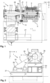
- the Figure 1 shows a side sectional view through a drive machine 1 according to the invention, which includes a drive shaft 3 and an electric motor 2 designed as a synchronous machine.
- the drive shaft 3 is designed as a belt shaft and drives a total of five belts 5, which are designed as flat belts.
- the drive shaft 3 is mounted on both sides in respective bearings 4a and 4b and can be driven by the electric motor 2.
- a rotor 6 of the electric motor 2 which carries permanent magnets, is connected to the drive shaft 3 in a gearless and rotationally fixed manner via a releasable coupling 7.
- the rotor 6 is designed as a hollow shaft 11 on the side of the drive shaft 3.
- the rotor 6 is designed as a solid shaft 25.
- an optical rotary encoder 21 in the form of an angle encoder is mounted on the front of the rotor 6, more precisely on the solid shaft 25, so that the current position of the rotor 6 can be detected by sensors.
- the drive shaft 3 forms a pin 12 on the motor side, which is inserted into the rotor 6, more precisely into the hollow shaft 11.
- the pin 12 or the axis of rotation 15 of the drive shaft 3 determines the axis of rotation 14 of the rotor 6 of the electric motor 2.
- the drive shaft 3 could also be designed as a hollow shaft 11 on the engine side.
- the rotor 6 would form a pin 12, which then engages in the drive shaft 3.
- an analogous clamping coupling 7 shown in the figures could be used, only in the reverse installation direction.
- the electric motor 2 is thus suspended freely in space on the drive shaft 3 by means of the coupling 7, the drive shaft 3 in turn being supported on a support structure 27 via the bearings 4a, 4b.
- the drive shaft 3 thus carries the electric motor 2.
- the two bearings 4a and 4b of the drive shaft 3 not only absorb the forces that are transmitted to the drive shaft 3 via the belts 5, but also the entire weight of the electric motor 2.
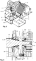
- the electric motor 2 Although it has several support feet 9, which serve to be able to temporarily turn off the electric motor 2 safely; However, when assembled, these feet 9 hang in the air, as shown in the views Figure 4 and Figure 5 is easy to see.
- the clutch 7 establishes a rotationally fixed connection between the drive shaft 3 and the rotor 6 by means of frictional engagement and without any positive connection.
- the coupling 7 has no elastic elements whatsoever.
- the clutch 7 is designed as a clamping clutch and includes a clamping element 16 and an associated counter-tensioning element 17, which are axially braced against one another by means of a screw connection 20.
- the (radially outer) clamping element 16 forms an inner cone 18, on which an outer cone 19 rests, which is formed by the (radially inner) counter-clamping element 17.
- These elements 17, 18, 20 thus form a ring clamping element.
- the inner counter-tensioning element 17 is supported axially on a step 22, which is formed on the outside circumference of the drive shaft 3, in the area of the clutch 7.
- the clamping clutch 7 offers a conical clutch surface 30, which produces a desired frictional connection.
- the clutch 7 is set so far in the axial direction into the electric motor 2 that said clutch surface 30 penetrates a radial plane in which the in the Figures 7 and 8 A bearing 23 of the electric motor 2 that can be seen is arranged, which supports the rotor 6 (compare the dotted lines in Figure 8 ).
- a mounting gap 13 is kept free between the motor-side bearing 4b of the drive shaft 3 and the electric motor 2. This makes it possible to tighten the coupling 7 using hand tools when assembling the electric motor 2 on the drive shaft 3 and to loosen it again later, since the assembly gap 13 is designed to be sufficiently large to be able to handle the Hand tools to access the screw connection 20 of the coupling 7.
- the torque support 10 has a pin 32 which is connected to the housing 8 of the electric motor 2 by means of a screw connection 20 (see Figure 7 ).
- the pin 32 is rotatably and axially displaceably mounted in a bearing 4 of the torque arm 10.
- the torque arm 10 is mounted on the supporting structure 27 with a second bearing 4. Due to the two bearings 4 of the torque arm 9, it can determine an angular position of the housing 8 of the electric motor 2 in relation to a rotation axis 14 of the electric motor 2 (cf. Fig. 1 ) and thus prevent the housing 8 from rotating when the electric motor 2 is energized.
- the torque support 10 cannot determine any other degrees of freedom for the position of the electric motor 2 in space and cannot absorb any axial forces in relation to the axis of rotation 15 of the drive shaft 3 (cf. Fig. 7 ). This avoids overdetermination and only the angular position of the electric motor 2 is determined by the torque arm 10. Otherwise, the electric motor 2 is suspended freely in space on the drive shaft 3. How to be good at Figure 6 recognizes, the torque arm 10 is arranged in the mounting gap 13.
- the drive machine 1 also includes a deflection roller 28, which deflects the total of five carrying belts 5, whereby other numbers of belts 5 can also be used.
- the deflection roller 28 can be moved on the support structure 27, so that a distance between the deflection roller 28 and the drive shaft 2 (in the x direction in Figure 2 ) is adjustable. Also in the Figures 3 and 4 Both positions of the single deflection roller 28 are illustrated (note the block arrows there too).
- a first belt side 33 can run to the elevator car or to a counterweight. Accordingly, the second belt side 34 can then run to the counterweight or to the car, depending on the design of the elevator shaft.
- the drive machine 1 according to the invention can therefore be used in different elevator constellations.
- the drive machine 1 also includes a braking device 26 for braking the drive shaft 3.
- This braking device 26 is designed as an electromagnetic holding brake and has a brake disk 29 which is connected to the drive shaft 3 in a rotationally fixed manner. The brake shoes of the braking device 26 thus act on the brake disk 29 and thereby brake the drive shaft 3 and can also hold it in a certain rotational position.
- the braking device 26 is arranged between the bearings 4a and 4b on both sides of the drive shaft 3 and is therefore on the output side of the clutch 7 (i.e. on the side of the drive shaft 3 and not on the side of the electric motor 2). Even if, for example, the frictional connection of the Should the clutch 7 fail and the rotation-proof connection between the rotor 6 and the drive shaft 3 would be broken, the braking device 26 can hold the drive shaft 3 securely.
- the braking device 26 is designed in such a way that the holding force is exerted in the de-energized state (due to a mechanical restoring element).
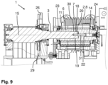
- FIG. 9 shows a further possible embodiment of a drive machine 1 according to the invention, although here no separate ring clamping element is used as a clutch 7, but rather the clutch 7 is formed directly by the drive shaft 3 and the rotor 6.
- the rotor 6 is again designed as a hollow shaft 11 on the drive side and thus offers a receptacle into which the drive shaft 3 is inserted, ie the electric motor 2 is plugged onto the drive shaft 3 here.
- the rotor 6 forms an inner cone 18, which fits an outer cone 19, which the drive shaft 3 forms at its motor-side end.
- a conical coupling surface 30 is thus formed between the drive shaft 3 and the rotor 6.
- a tightening screw 31 which is arranged centrally on and along the axis of rotation 14 of the rotor 6, is guided through a passage in the rotor 6 to the drive shaft 3 and there engages in a thread in the drive shaft 3.
- the tightening screw 31 is supported on a step/shoulder 22 which is formed on the rotor 6.
- the tightening force creates a frictional connection between the drive shaft 3 and the rotor 6, whereby the desired rotation-proof connection and thus a direct drive of the drive shaft 3 is achieved.
- using the cone-shaped Coupling surface 30 of the rotor 6 is centered on the drive shaft 3, so that the axis of rotation 14 of the rotor 6 and the axis of rotation 15 of the drive shaft 3 coincide.
- the inner cone 18 could also be designed on the drive shaft 3, for example.
- the rotor 6 could be inserted into the drive shaft 3 and the frictional connection to the drive shaft 3 could be produced by means of a suitable outer cone 19 at the drive-side end of the rotor 6.
- the tightening screw 31 could also be used, for example (in Figure 9 from left to right) through a passage in the drive shaft 3 into a thread that is formed in the rotor 6.
- the drive shaft 3 would therefore be designed (at least in sections) as a hollow shaft 11.
Landscapes
- Engineering & Computer Science (AREA)
- Civil Engineering (AREA)
- Mechanical Engineering (AREA)
- Structural Engineering (AREA)
- Connection Of Motors, Electrical Generators, Mechanical Devices, And The Like (AREA)
Applications Claiming Priority (1)
| Application Number | Priority Date | Filing Date | Title |
|---|---|---|---|
| DE102022109725.0A DE102022109725A1 (de) | 2022-04-22 | 2022-04-22 | Modulare Antriebsmaschine für einen Aufzug |
Publications (2)
| Publication Number | Publication Date |
|---|---|
| EP4265556A1 true EP4265556A1 (fr) | 2023-10-25 |
| EP4265556B1 EP4265556B1 (fr) | 2025-02-12 |
Family
ID=86051865
Family Applications (1)
| Application Number | Title | Priority Date | Filing Date |
|---|---|---|---|
| EP23168005.9A Active EP4265556B1 (fr) | 2022-04-22 | 2023-04-14 | Machine d'entraînement pour ascenseur |
Country Status (2)
| Country | Link |
|---|---|
| EP (1) | EP4265556B1 (fr) |
| DE (1) | DE102022109725A1 (fr) |
Families Citing this family (1)
| Publication number | Priority date | Publication date | Assignee | Title |
|---|---|---|---|---|
| DE102024104740A1 (de) * | 2024-02-20 | 2025-03-06 | Tk Elevator Innovation And Operations Gmbh | Riementriebeinheit für Aufzugsanlagen, Aufzugsanlage sowie Verfahren und Verwendung |
Citations (3)
| Publication number | Priority date | Publication date | Assignee | Title |
|---|---|---|---|---|
| WO2009075670A1 (fr) * | 2007-12-10 | 2009-06-18 | Otis Elevator Company | Ensemble cabine d'ascenseur comprenant un moteur basé sur le couple |
| DE102016120645A1 (de) * | 2016-10-28 | 2018-05-03 | Logos-Innovationen Gmbh | Hebevorrichtung, insbesondere Aufzug oder Hebebühne |
| WO2019121955A1 (fr) * | 2017-12-19 | 2019-06-27 | Thyssenkrupp Elevator Ag | Unité d'entraînement d'ascenseur |
Family Cites Families (5)
| Publication number | Priority date | Publication date | Assignee | Title |
|---|---|---|---|---|
| DE19924735A1 (de) | 1999-05-31 | 2001-03-15 | Sew Eurodrive Gmbh & Co | Baureihe von Elektromotoren mit Drehzahlrückführung und Elektromotor mit Drehzahlrückführung |
| DE102004047431A1 (de) | 2003-10-01 | 2005-04-21 | Logos Innovationen Gmbh | Hebevorrichtung, insbesondere Aufzug oder Hebebühne |
| DE202005015876U1 (de) | 2005-10-07 | 2005-12-29 | Bullinger, Rudolf | Vorrichtung zum hilfsweisen Antrieb eines Rads |
| DE102010029071A1 (de) | 2010-05-18 | 2011-11-24 | Bayerische Motoren Werke Aktiengesellschaft | Radantrieb für ein Fahrzeug |
| DE102014011929A1 (de) | 2014-08-14 | 2016-02-18 | Fromm Holding Ag | Antriebseinheit für ein Umreifungsgerät |
-
2022
- 2022-04-22 DE DE102022109725.0A patent/DE102022109725A1/de not_active Withdrawn
-
2023
- 2023-04-14 EP EP23168005.9A patent/EP4265556B1/fr active Active
Patent Citations (3)
| Publication number | Priority date | Publication date | Assignee | Title |
|---|---|---|---|---|
| WO2009075670A1 (fr) * | 2007-12-10 | 2009-06-18 | Otis Elevator Company | Ensemble cabine d'ascenseur comprenant un moteur basé sur le couple |
| DE102016120645A1 (de) * | 2016-10-28 | 2018-05-03 | Logos-Innovationen Gmbh | Hebevorrichtung, insbesondere Aufzug oder Hebebühne |
| WO2019121955A1 (fr) * | 2017-12-19 | 2019-06-27 | Thyssenkrupp Elevator Ag | Unité d'entraînement d'ascenseur |
Also Published As
| Publication number | Publication date |
|---|---|
| DE102022109725A1 (de) | 2023-10-26 |
| EP4265556B1 (fr) | 2025-02-12 |
Similar Documents
| Publication | Publication Date | Title |
|---|---|---|
| DE69909133T2 (de) | Aufzugsantrieb mit gegenläufigen rotoren | |
| DE69420329T2 (de) | Im Gegengewicht eingebauter Aufzugsmotor | |
| EP3440003A1 (fr) | Unité d'entraînement pour système d'ascenseur | |
| EP3317222A1 (fr) | Ensemble formant treuil de levage | |
| AT516038B1 (de) | Antriebsstrang | |
| DE3216978A1 (de) | Kaefiglaeufermotor fuer ein hebezeug, insbesondere fuer einen aufzug | |
| EP3668662A1 (fr) | Entraînement direct pour rouleaux, cylindres et treuils dans l'industrie de l'acier/des métaux non ferreux | |
| EP4192621B1 (fr) | Broyeur à billes de laboratoire | |
| DE19634629B4 (de) | Getriebelose Antriebsvorrichtung für Aufzüge | |
| EP4265556B1 (fr) | Machine d'entraînement pour ascenseur | |
| EP0834463A1 (fr) | Dispositif compact d'entraínement pour ascenseur | |
| EP2147884B1 (fr) | Dispositif de levage, notamment ascenseur ou élévateur | |
| EP2061136A1 (fr) | Engrenage direct électrique pour un cylindre | |
| DE60204256T2 (de) | Durch Drehmoment lösbare Scheibenbremse | |
| EP3536404B1 (fr) | Dispositif support pour un couple cinématique et application industrielle | |
| EP0673874A1 (fr) | Entraînement pour ascenseur | |
| DE102016120645A1 (de) | Hebevorrichtung, insbesondere Aufzug oder Hebebühne | |
| EP1069068A1 (fr) | Entraínement compact pour un ascenseur | |
| DE102010031107B4 (de) | Umformpresse mit einem Stößeldirektantrieb | |
| DE10005075A1 (de) | Elektrisch angetriebene Winde, insbesondere Theaterwinde | |
| EP1048603A1 (fr) | Disposition inclinée de la machinerie d'un ascenseur à câbles | |
| DE10136030B4 (de) | Trommelantrieb für eine Fahrtreppe oder einen Fahrsteig | |
| EP3665765A1 (fr) | Générateur pour une éolienne et éolienne comprenant celui-ci | |
| EP3452399A1 (fr) | Dispositif de levage, en particulier ascenseur ou plate-forme de levage | |
| EP2004895B1 (fr) | Procede et systeme d'entrainement permettant de faire fonctionner un metier a tisser |
Legal Events
| Date | Code | Title | Description |
|---|---|---|---|
| STAA | Information on the status of an ep patent application or granted ep patent |
Free format text: STATUS: THE APPLICATION HAS BEEN PUBLISHED |
|
| PUAI | Public reference made under article 153(3) epc to a published international application that has entered the european phase |
Free format text: ORIGINAL CODE: 0009012 |
|
| AK | Designated contracting states |
Kind code of ref document: A1 Designated state(s): AL AT BE BG CH CY CZ DE DK EE ES FI FR GB GR HR HU IE IS IT LI LT LU LV MC ME MK MT NL NO PL PT RO RS SE SI SK SM TR |
|
| STAA | Information on the status of an ep patent application or granted ep patent |
Free format text: STATUS: REQUEST FOR EXAMINATION WAS MADE |
|
| 17P | Request for examination filed |
Effective date: 20231207 |
|
| RBV | Designated contracting states (corrected) |
Designated state(s): AL AT BE BG CH CY CZ DE DK EE ES FI FR GB GR HR HU IE IS IT LI LT LU LV MC ME MK MT NL NO PL PT RO RS SE SI SK SM TR |
|
| GRAP | Despatch of communication of intention to grant a patent |
Free format text: ORIGINAL CODE: EPIDOSNIGR1 |
|
| STAA | Information on the status of an ep patent application or granted ep patent |
Free format text: STATUS: GRANT OF PATENT IS INTENDED |
|
| GRAS | Grant fee paid |
Free format text: ORIGINAL CODE: EPIDOSNIGR3 |
|
| INTG | Intention to grant announced |
Effective date: 20241204 |
|
| GRAA | (expected) grant |
Free format text: ORIGINAL CODE: 0009210 |
|
| STAA | Information on the status of an ep patent application or granted ep patent |
Free format text: STATUS: THE PATENT HAS BEEN GRANTED |
|
| AK | Designated contracting states |
Kind code of ref document: B1 Designated state(s): AL AT BE BG CH CY CZ DE DK EE ES FI FR GB GR HR HU IE IS IT LI LT LU LV MC ME MK MT NL NO PL PT RO RS SE SI SK SM TR |
|
| REG | Reference to a national code |
Ref country code: GB Ref legal event code: FG4D Free format text: NOT ENGLISH |
|
| REG | Reference to a national code |
Ref country code: CH Ref legal event code: EP |
|
| REG | Reference to a national code |
Ref country code: DE Ref legal event code: R096 Ref document number: 502023000550 Country of ref document: DE |
|
| REG | Reference to a national code |
Ref country code: IE Ref legal event code: FG4D Free format text: LANGUAGE OF EP DOCUMENT: GERMAN |
|
| P01 | Opt-out of the competence of the unified patent court (upc) registered |
Free format text: CASE NUMBER: APP_11705/2025 Effective date: 20250311 |
|
| REG | Reference to a national code |
Ref country code: NL Ref legal event code: MP Effective date: 20250212 |
|
| PG25 | Lapsed in a contracting state [announced via postgrant information from national office to epo] |
Ref country code: RS Free format text: LAPSE BECAUSE OF FAILURE TO SUBMIT A TRANSLATION OF THE DESCRIPTION OR TO PAY THE FEE WITHIN THE PRESCRIBED TIME-LIMIT Effective date: 20250512 |
|
| PG25 | Lapsed in a contracting state [announced via postgrant information from national office to epo] |
Ref country code: FI Free format text: LAPSE BECAUSE OF FAILURE TO SUBMIT A TRANSLATION OF THE DESCRIPTION OR TO PAY THE FEE WITHIN THE PRESCRIBED TIME-LIMIT Effective date: 20250212 |
|
| PG25 | Lapsed in a contracting state [announced via postgrant information from national office to epo] |
Ref country code: PL Free format text: LAPSE BECAUSE OF FAILURE TO SUBMIT A TRANSLATION OF THE DESCRIPTION OR TO PAY THE FEE WITHIN THE PRESCRIBED TIME-LIMIT Effective date: 20250212 |
|
| PGFP | Annual fee paid to national office [announced via postgrant information from national office to epo] |
Ref country code: DE Payment date: 20250513 Year of fee payment: 3 |
|
| PG25 | Lapsed in a contracting state [announced via postgrant information from national office to epo] |
Ref country code: ES Free format text: LAPSE BECAUSE OF FAILURE TO SUBMIT A TRANSLATION OF THE DESCRIPTION OR TO PAY THE FEE WITHIN THE PRESCRIBED TIME-LIMIT Effective date: 20250212 |
|
| REG | Reference to a national code |
Ref country code: LT Ref legal event code: MG9D |
|
| PG25 | Lapsed in a contracting state [announced via postgrant information from national office to epo] |
Ref country code: IS Free format text: LAPSE BECAUSE OF FAILURE TO SUBMIT A TRANSLATION OF THE DESCRIPTION OR TO PAY THE FEE WITHIN THE PRESCRIBED TIME-LIMIT Effective date: 20250612 Ref country code: NO Free format text: LAPSE BECAUSE OF FAILURE TO SUBMIT A TRANSLATION OF THE DESCRIPTION OR TO PAY THE FEE WITHIN THE PRESCRIBED TIME-LIMIT Effective date: 20250512 |
|
| PG25 | Lapsed in a contracting state [announced via postgrant information from national office to epo] |
Ref country code: NL Free format text: LAPSE BECAUSE OF FAILURE TO SUBMIT A TRANSLATION OF THE DESCRIPTION OR TO PAY THE FEE WITHIN THE PRESCRIBED TIME-LIMIT Effective date: 20250212 |
|
| PG25 | Lapsed in a contracting state [announced via postgrant information from national office to epo] |
Ref country code: HR Free format text: LAPSE BECAUSE OF FAILURE TO SUBMIT A TRANSLATION OF THE DESCRIPTION OR TO PAY THE FEE WITHIN THE PRESCRIBED TIME-LIMIT Effective date: 20250212 |
|
| PG25 | Lapsed in a contracting state [announced via postgrant information from national office to epo] |
Ref country code: PT Free format text: LAPSE BECAUSE OF FAILURE TO SUBMIT A TRANSLATION OF THE DESCRIPTION OR TO PAY THE FEE WITHIN THE PRESCRIBED TIME-LIMIT Effective date: 20250612 Ref country code: LV Free format text: LAPSE BECAUSE OF FAILURE TO SUBMIT A TRANSLATION OF THE DESCRIPTION OR TO PAY THE FEE WITHIN THE PRESCRIBED TIME-LIMIT Effective date: 20250212 |
|
| PG25 | Lapsed in a contracting state [announced via postgrant information from national office to epo] |
Ref country code: GR Free format text: LAPSE BECAUSE OF FAILURE TO SUBMIT A TRANSLATION OF THE DESCRIPTION OR TO PAY THE FEE WITHIN THE PRESCRIBED TIME-LIMIT Effective date: 20250513 Ref country code: BG Free format text: LAPSE BECAUSE OF FAILURE TO SUBMIT A TRANSLATION OF THE DESCRIPTION OR TO PAY THE FEE WITHIN THE PRESCRIBED TIME-LIMIT Effective date: 20250212 |
|
| PGFP | Annual fee paid to national office [announced via postgrant information from national office to epo] |
Ref country code: AT Payment date: 20250721 Year of fee payment: 3 |
|
| PG25 | Lapsed in a contracting state [announced via postgrant information from national office to epo] |
Ref country code: SE Free format text: LAPSE BECAUSE OF FAILURE TO SUBMIT A TRANSLATION OF THE DESCRIPTION OR TO PAY THE FEE WITHIN THE PRESCRIBED TIME-LIMIT Effective date: 20250212 |
|
| PG25 | Lapsed in a contracting state [announced via postgrant information from national office to epo] |
Ref country code: SM Free format text: LAPSE BECAUSE OF FAILURE TO SUBMIT A TRANSLATION OF THE DESCRIPTION OR TO PAY THE FEE WITHIN THE PRESCRIBED TIME-LIMIT Effective date: 20250212 |
|
| PG25 | Lapsed in a contracting state [announced via postgrant information from national office to epo] |
Ref country code: DK Free format text: LAPSE BECAUSE OF FAILURE TO SUBMIT A TRANSLATION OF THE DESCRIPTION OR TO PAY THE FEE WITHIN THE PRESCRIBED TIME-LIMIT Effective date: 20250212 |
|
| PG25 | Lapsed in a contracting state [announced via postgrant information from national office to epo] |
Ref country code: IT Free format text: LAPSE BECAUSE OF FAILURE TO SUBMIT A TRANSLATION OF THE DESCRIPTION OR TO PAY THE FEE WITHIN THE PRESCRIBED TIME-LIMIT Effective date: 20250212 |
|
| PG25 | Lapsed in a contracting state [announced via postgrant information from national office to epo] |
Ref country code: EE Free format text: LAPSE BECAUSE OF FAILURE TO SUBMIT A TRANSLATION OF THE DESCRIPTION OR TO PAY THE FEE WITHIN THE PRESCRIBED TIME-LIMIT Effective date: 20250212 Ref country code: CZ Free format text: LAPSE BECAUSE OF FAILURE TO SUBMIT A TRANSLATION OF THE DESCRIPTION OR TO PAY THE FEE WITHIN THE PRESCRIBED TIME-LIMIT Effective date: 20250212 |
|
| PG25 | Lapsed in a contracting state [announced via postgrant information from national office to epo] |
Ref country code: RO Free format text: LAPSE BECAUSE OF FAILURE TO SUBMIT A TRANSLATION OF THE DESCRIPTION OR TO PAY THE FEE WITHIN THE PRESCRIBED TIME-LIMIT Effective date: 20250212 |
|
| PG25 | Lapsed in a contracting state [announced via postgrant information from national office to epo] |
Ref country code: SK Free format text: LAPSE BECAUSE OF FAILURE TO SUBMIT A TRANSLATION OF THE DESCRIPTION OR TO PAY THE FEE WITHIN THE PRESCRIBED TIME-LIMIT Effective date: 20250212 |
|
| REG | Reference to a national code |
Ref country code: DE Ref legal event code: R097 Ref document number: 502023000550 Country of ref document: DE |
|
| PG25 | Lapsed in a contracting state [announced via postgrant information from national office to epo] |
Ref country code: LU Free format text: LAPSE BECAUSE OF NON-PAYMENT OF DUE FEES Effective date: 20250414 |
|
| PLBE | No opposition filed within time limit |
Free format text: ORIGINAL CODE: 0009261 |
|
| STAA | Information on the status of an ep patent application or granted ep patent |
Free format text: STATUS: NO OPPOSITION FILED WITHIN TIME LIMIT |
|
| PG25 | Lapsed in a contracting state [announced via postgrant information from national office to epo] |
Ref country code: MC Free format text: LAPSE BECAUSE OF FAILURE TO SUBMIT A TRANSLATION OF THE DESCRIPTION OR TO PAY THE FEE WITHIN THE PRESCRIBED TIME-LIMIT Effective date: 20250212 |
|
| REG | Reference to a national code |
Ref country code: BE Ref legal event code: MM Effective date: 20250430 |
|
| PG25 | Lapsed in a contracting state [announced via postgrant information from national office to epo] |
Ref country code: FR Free format text: LAPSE BECAUSE OF NON-PAYMENT OF DUE FEES Effective date: 20250430 |
|
| PG25 | Lapsed in a contracting state [announced via postgrant information from national office to epo] |
Ref country code: BE Free format text: LAPSE BECAUSE OF NON-PAYMENT OF DUE FEES Effective date: 20250430 |
|
| 26N | No opposition filed |
Effective date: 20251113 |
|
| PG25 | Lapsed in a contracting state [announced via postgrant information from national office to epo] |
Ref country code: IE Free format text: LAPSE BECAUSE OF NON-PAYMENT OF DUE FEES Effective date: 20250414 |