EP4266101A1 - Armoire de distribution - Google Patents
Armoire de distribution Download PDFInfo
- Publication number
- EP4266101A1 EP4266101A1 EP23165797.4A EP23165797A EP4266101A1 EP 4266101 A1 EP4266101 A1 EP 4266101A1 EP 23165797 A EP23165797 A EP 23165797A EP 4266101 A1 EP4266101 A1 EP 4266101A1
- Authority
- EP
- European Patent Office
- Prior art keywords
- distribution cabinet
- power distribution
- cabinet
- housing
- receptacle
- Prior art date
- Legal status (The legal status is an assumption and is not a legal conclusion. Google has not performed a legal analysis and makes no representation as to the accuracy of the status listed.)
- Pending
Links
Images
Classifications
-
- G—PHYSICS
- G02—OPTICS
- G02B—OPTICAL ELEMENTS, SYSTEMS OR APPARATUS
- G02B6/00—Light guides; Structural details of arrangements comprising light guides and other optical elements, e.g. couplings
- G02B6/44—Mechanical structures for providing tensile strength and external protection for fibres, e.g. optical transmission cables
- G02B6/4439—Auxiliary devices
- G02B6/444—Systems or boxes with surplus lengths
- G02B6/4453—Cassettes
- G02B6/4455—Cassettes characterised by the way of extraction or insertion of the cassette in the distribution frame, e.g. pivoting, sliding, rotating or gliding
-
- G—PHYSICS
- G02—OPTICS
- G02B—OPTICAL ELEMENTS, SYSTEMS OR APPARATUS
- G02B6/00—Light guides; Structural details of arrangements comprising light guides and other optical elements, e.g. couplings
- G02B6/44—Mechanical structures for providing tensile strength and external protection for fibres, e.g. optical transmission cables
- G02B6/4439—Auxiliary devices
- G02B6/444—Systems or boxes with surplus lengths
- G02B6/4452—Distribution frames
- G02B6/44526—Panels or rackmounts covering a whole width of the frame or rack
-
- G—PHYSICS
- G02—OPTICS
- G02B—OPTICAL ELEMENTS, SYSTEMS OR APPARATUS
- G02B6/00—Light guides; Structural details of arrangements comprising light guides and other optical elements, e.g. couplings
- G02B6/44—Mechanical structures for providing tensile strength and external protection for fibres, e.g. optical transmission cables
- G02B6/4439—Auxiliary devices
- G02B6/444—Systems or boxes with surplus lengths
- G02B6/4453—Cassettes
- G02B6/4454—Cassettes with splices
-
- H—ELECTRICITY
- H04—ELECTRIC COMMUNICATION TECHNIQUE
- H04Q—SELECTING
- H04Q1/00—Details of selecting apparatus or arrangements
- H04Q1/02—Constructional details
- H04Q1/021—Constructional details using pivoting mechanisms for accessing the interior of the apparatus
Definitions
- the present invention relates to a network distribution cabinet for fiber optic lines.
- Such power distribution cabinets are known from the prior art. Fiber optic lines coming from the providers are usually introduced into these, stored via cassette systems and connected to outgoing fiber optic lines, which in turn are routed to the consumers. For this purpose, the fiber optic lines (provider lines) entering the network distribution cabinet can be spliced and/or patched before they leave the network distribution cabinet again as outgoing fiber optic lines (consumer lines) with any remaining provider lines.
- the network distribution cabinet comprises a housing in which fiber optic cables can be laid from a lower entrance area to splice points, the housing having a rear wall, a top wall, side walls and an openable door. Furthermore, the power distribution cabinet in the housing has a pivotable wall between its rear wall and the door, which is attached to the side walls of the housing and can be swung out to the side. On the front of the pivoting wall there are, among other things, splice cassette holders with splice cassettes to which the fiber optic cables are laid.
- a technician In order to distribute the provider lines to the consumers, a technician must lay the provider and consumer lines in the network distribution cabinet and connect them at at least one connection point, i.e. splice and/or patch them. This work is usually complex and is carried out by the technician crouching in front of the power distribution cabinet.
- One object of the invention is to provide an easy-to-use and ergonomic power distribution cabinet.
- the invention relates to a network distribution cabinet for fiber optic lines.
- the network distribution cabinet is used to divide fiber optic lines, in particular to distribute (fiber optic) provider lines to individual consumers.
- fiber optic cables (provider lines) are introduced into the network distribution cabinet, divided there and connected to individual consumer lines, which in turn leave the network distribution cabinet with any remaining provider lines.
- the respective connection point(s) of the fiber optic cables, at which they were connected to one another by splicing and/or patching, is usually located in a splice cassette arranged in the network distribution cabinet.
- the splice cassette can have means for accommodating fiber optic cables, in particular their reserve length, and/or connectors for fiber optic cables.
- the power distribution cabinet has a housing which comprises a rear wall, a cabinet ceiling, a first side wall, a second side wall, and a cabinet opening opposite the rear wall.
- the housing can be opposite the cabinet ceiling Include cabinet base.
- the power distribution cabinet can also have a cover which serves to close the cabinet opening.
- the cover may include at least one cabinet door and may be attached to the housing via one or more hinges. Ie the cover can be designed in several parts. In particular, it is possible to divide the cover into an upper cover for an upper housing area and a lower cover for a lower housing area.
- the top cover can have at least one cabinet door.
- the first sidewall and second sidewall each extend in a vertical direction. In an assembled state of the power distribution cabinet, the vertical direction is defined parallel to the direction of gravity. Ie a horizontal direction arranged perpendicular to the vertical direction is defined parallel to the ground.
- the housing can further have at least one opening for introducing fiber optic cables into the network distribution cabinet (provider lines) and/or leading fiber optic lines out of the network distribution cabinet (consumer lines and possibly remaining provider lines).
- the at least one opening is advantageously arranged in a lower housing region of the housing.
- the opening can be arranged in the rear wall and/or the first side wall and/or the second side wall and/or the cabinet floor.
- the housing advantageously has an (introduction) opening in the first side wall for inserting fiber optic cables and in the second side wall a further (exit) opening opposite this for leading out fiber optic cables.
- the power distribution cabinet also includes a swivel plate. At least one receptacle for a (respective) splice cassette is attached to the inside of the swivel plate.
- the pivot plate can be pivotable from a first position, in which the at least one receptacle is arranged essentially within the housing, into a second position, in which the at least one receptacle is arranged in the vertical direction above the cabinet ceiling.
- the pivot plate extends in a longitudinal direction of the pivot plate from a proximal end to a distal end. The proximal end is the end via which the pivot plate is operatively connected to the housing in a pivotable manner.
- the inside of the swivel plate can face the back of the power distribution cabinet.
- the inside can face away from the ceiling of the power distribution cabinet.
- the at least one receptacle is also arranged within a contour of the cabinet ceiling in the second position, viewed from the vertical direction. Furthermore, depending on the design, it is possible for the pivot plate and the at least one receptacle to be arranged in the first position within the housing, in particular the upper housing area.
- the pivot plate can be pivotable about a horizontal pivot axis.
- the horizontal pivot axis can be arranged in the area of an edge of the cabinet ceiling, which limits the cabinet opening in certain areas.
- the pivot axis advantageously runs through a joint.
- the joint can therefore effectively connect the swivel plate to the cabinet ceiling.
- the joint can include a removable element, such as a pin, so that removing the element makes the operative connection between the pivot plate and the cupboard ceiling can be lifted. In this way, the pivot plate can be completely detached from the housing of the power distribution cabinet if this should be necessary.
- the pivot plate can be operatively connected to the housing via a pivot arm.
- the swivel arm is advantageously attached to an inside of the housing.
- the swivel arm can have several joints and/or swivel axes.
- the pivot arm can have at least one locking means for fixing one or more joints.
- a swivel arm has the advantage that a more individual adjustment of the second position of the swivel plate is possible.
- the swivel arm is also advantageously arranged completely within the housing.
- the power distribution cabinet can include a fixing structure for the pivot plate in the first position, in which the at least one receptacle is arranged essentially within the housing.
- the fixing structure protects the inserted fiber optic cables from damage, which are arranged in the housing, in particular between the pivot plate in the first position and the back of the housing.
- the fixing structure can comprise a first fixing element arranged on the pivot plate and a second fixing element arranged on the housing, in particular the first and/or second side wall, which cooperate in such a way that the pivot plate is positioned in a defined position in the first position. In the defined position, the longitudinal direction of the pivot plate extends Advantage parallel to vertical direction.
- the fixing structure can, for example, comprise a magnetic stop, a locking tongue, a locking catch or the like, or the first and/or second fixing element can, for example, be a magnetic stop, a locking tongue, a locking catch or the like.
- the multiple receptacles can be arranged like a matrix on the inside of the pivot plate.
- a series of several receptacles can extend in the longitudinal direction of the pivot plate.
- two or more rows of receptacles extend along the inside of the swivel plate.
- the respective receptacle for a splice cassette can include a recess for receiving the respective splice cassette in certain areas.
- the recess advantageously extends in the transverse direction of the respective pivot plate.
- the receptacle advantageously comprises at least one latching element for latching connection to the respective splice cassette.
- the at least one receptacle can be designed in such a way that a splice cassette accommodated in it can be tilted from a first position to a second position (about a tilt axis).
- the splice cassette accommodated in the respective receptacle In the first position, the splice cassette accommodated in the respective receptacle is inclined towards the distal end of the pivoting plate, while the splice cassette is in the second position is inclined towards the proximal end of the pivot plate.
- the (respective) tilt axis of the at least one receptacle is advantageously parallel to the pivot axis.
- the tilt axis is also advantageously located close to the inside of the pivot plate.
- the splice cassette(s) can belong to the power distribution cabinet or can only be installed later.
- the first and/or the second position of the at least one receptacle is inherently stable in the second position of the pivot plate.
- intrinsically stable it is meant that the splice cassette remains in the respective position (under the effect of gravity) without any external force (e.g. from the fitter).
- A corresponds to an angle between the splice cassette that can be arranged in the at least one receptacle in the first position and the swivel plate and B corresponds to an angle between the swivel plate and the cabinet ceiling in the second position
- the relationship A ⁇ 90 ° - B applies.
- Good stability and ergonomics are created when the angle A is between 40° - 70°.
- Good ergonomics is ensured, for example, by the fact that the fitter does not have to bend down into the housing, but can work comfortably while standing (or sitting - depending on the height of the cabinet) from above and in front of the power distribution cabinet.
- a stop element for the splice cassette(s) can be attached in front of and/or behind the at least one receptacle (or the row of receptacles or the receptacle structure).
- a front stop element in front of the at least one receptacle (ie in the area of the proximal end of the pivot plate) and/or behind it
- a rear stop element is arranged in the at least one receptacle (ie in the area of the distal end of the pivot plate).
- the front stop element positions the respective splice cassette(s) in the second position, while the rear stop element positions the respective splice cassette(s) in the first position.
- the rear stop element can thus define the angle A of the splice cassette in the first position to the inside of the pivoting plate, or the front stop element can define the angle of the splice cassette in the second position to the inside of the pivoting plate.
- a support structure for (reproducibly) supporting the pivot plate in the second position can be arranged between an outside of the pivot plate and an outside of the housing.
- the support structure can also provide several alternative second positions.
- the support structure may include a handle and optionally a holder for the handle.
- the handle can be arranged on the outside of the pivot plate.
- the optional holder can be arranged on the outside of the housing so that the handle can be positioned in it.
- the support structure can also have several brackets, so that alternative second positions are provided, or the angle A can be changed depending on the task of the fitter.
- the power distribution cabinet can include a mixing element (also called a mixer). This is used to connect fiber optic cables from one series of receptacles with fiber optic cables from another series of receptacles.
- the mixing element can also be arranged on the inside of the pivot plate. It is advantageous to have one mixing element per row of recordings available. This can be arranged, for example, at the end of the row of receptacles which faces the proximal end of the pivot plate.
- At least one strain relief element can be arranged at the proximal end and on the inside of the pivot plate.
- the strain relief element serves to relieve the fiber optic cables of tensile forces, particularly in the second position of the pivoting plate and/or when pivoting the pivoting plate.
- the strain relief element is advantageously arranged next to the joint of the pivot plate.
- the strain relief element can be arranged, for example, between the mixing element and the joint.
- the power distribution cabinet can be divided into an upper and a lower housing area.
- the lower housing area can be used to be sunk into the ground, at least in some areas. Equivalently, the upper housing area can serve to be above ground.
- the opening into the power distribution cabinet can be located in the lower housing area.
- holding elements for holding fiber optic cables can be arranged in an interior of the housing and in the upper housing area.
- the plurality of holding elements are advantageously arranged along the rear wall.
- these can be arranged along an annular contour.
- at least one of the plurality of holding elements is arranged to be displaceable in such a way that the circumference around the annular contour is variable.
- at least one of the plurality of holding elements can be displaceable in at least a first and/or second direction be.
- the first direction may point in the horizontal direction and/or the second direction may point in the vertical direction.
- a pipe mounting plate can be arranged between the upper and lower housing areas.
- the pipe mounting plate has a large number of insertion openings and a large number of exit openings.
- the insertion openings are used to insert fiber optic cables, in particular the provider cables, into the upper housing area.
- the exit openings are used to lead fiber optic lines, in particular consumer lines, out of the upper housing area.
- the fiber optic cables that are led in or out are usually routed in microducts.
- the outlet openings therefore advantageously have means for holding microtubes.
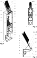
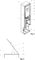
- FIG. 1 to Figure 4 show a power distribution cabinet 1 according to the invention with a housing 2, which comprises a rear wall 3, a cabinet ceiling 4, a first side wall 5, a second side wall 6, and a cabinet opening 9 opposite the rear wall 3.
- the first and second side walls 5, 6 each extend in a vertical direction (z direction).
- the housing 2 can further include a cabinet floor 7 opposite the cabinet ceiling 4.
- a cover 13 which serves to close the cabinet opening 9, is only shown schematically.
- the power distribution cabinet 1 is divided into an upper and a lower housing area 12, 11.
- a pipe mounting plate 24 is arranged between the lower and upper housing regions 11, 12.
- the power distribution cabinet 1 further has a swivel plate 8 with at least one receptacle 16 attached to an inside 14 of the swivel plate 8 for at least one splice cassette 17.
- a swivel plate 8 with at least one receptacle 16 attached to an inside 14 of the swivel plate 8 for at least one splice cassette 17.
- holding elements 25 for holding fiber optic cables can also be seen, which are arranged on the rear wall 3 (cf. Figure 2 ).
- the plurality of holding elements 25 are advantageously arranged along an annular contour and are displaceable in such a way that the circumference is variable around the annular contour.
- the fiber optic lines can thus be wrapped around the holding elements 25 and along the annular contour and then the holding elements 25 can be moved in such a way that the fiber optic lines are captively secured.
- the pivot plate 8 can be pivoted from a first position to a second position.
- the pivot plate 8 is shown in the first position, in which the at least one receptacle 16 is arranged essentially within the housing 2.
- the entire pivot plate 8 is advantageously arranged in the first position within the housing 2, in particular the upper housing region 11.
- a fixing structure 29, 30 ensures a defined position of the pivot plate 8 in the first position, so that fiber optic cables entering the upper housing area 12 through the pipe fastening plate 24 are not kinked by the pivot plate 8.
- a longitudinal direction of the pivot plate 8 advantageously points in the vertical direction.
- the fixing structure comprises a first fixing element 29 arranged on the pivot plate 8 and a second fixing element 30 arranged on the first and/or second side wall 5, 6, which are operatively connected to one another in the first position.
- the pivot plate 8 is shown in the second position, in which the at least one receptacle 16 is arranged in the vertical direction above the cabinet ceiling 4.
- the at least one receptacle 16 in the second position is also advantageously arranged within a contour of the cabinet ceiling 4.
- the pivot plate 8 is For this purpose, it can be pivoted about a horizontal pivot axis 18 and with the aid of a joint 22, which is arranged between the cabinet ceiling 4 and a pivot plate 8.
- the joint 22 can include a removable pin 23, so that the operative connection between the pivot plate 8 and the cabinet ceiling 4 can be canceled by removing the pin 23. In this way, the pivot plate 8 can be completely detached from the housing 2 of the power distribution cabinet 1 if this should be necessary.
- a support structure 19 for supporting the pivot plate 8 is arranged between an outside 15 of the pivot plate 8 and an outside of the housing.
- the handle can be temporarily positioned on the cabinet deck 4 by a holder 21 arranged on the outside of the housing.
- the pivot plate 8 extends in the longitudinal direction of the pivot plate 8 from a proximal end to a distal end.
- the proximal end is the end via which the pivot plate 8 is pivotally operatively connected to the housing 2.
- the splice cassette 17 accommodated in the respective receptacle 16 can be tiltable from a first position to a second position. In Figure 3 the splice cassettes 17 are visible in the first position.
- a front stop element 28 arranged in front of the row of receptacles 16 (ie in the area of the proximal end of the pivot plate 8) and a rear stop element 28 arranged behind the row, which Position splice cassettes 17 in the first position or second position.
- a mixing element 26 and a strain relief 27 are also arranged, as described above.
- FIG 5 a schematic view of the pivot plate 8 is shown in the second position.
- Power distribution cabinet 16 Recording 2 Housing 17 Splice cassette 3 Back wall 18 Pivot axis 4 Closet ceiling 19 Support structure 5 First side wall 20 Handle 6 Second side wall 21 bracket 7 Cabinet bottom 22 joint 8th Swivel plate 23 Pen 9 Cupboard opening 24 Pipe mounting plate 10 opening 25 Holding elements 11 Lower housing area 26 Mixing element 12 Upper housing area 27 Strain relief 13 cover 28 stop element 14 inside 29 First fixation element 15 outside 30 Second fixation element
Landscapes
- Physics & Mathematics (AREA)
- General Physics & Mathematics (AREA)
- Optics & Photonics (AREA)
- Light Guides In General And Applications Therefor (AREA)
Applications Claiming Priority (1)
| Application Number | Priority Date | Filing Date | Title |
|---|---|---|---|
| DE102022109405.7A DE102022109405A1 (de) | 2022-04-19 | 2022-04-19 | Netzverteilerschrank |
Publications (1)
| Publication Number | Publication Date |
|---|---|
| EP4266101A1 true EP4266101A1 (fr) | 2023-10-25 |
Family
ID=88069683
Family Applications (1)
| Application Number | Title | Priority Date | Filing Date |
|---|---|---|---|
| EP23165797.4A Pending EP4266101A1 (fr) | 2022-04-19 | 2023-03-31 | Armoire de distribution |
Country Status (2)
| Country | Link |
|---|---|
| EP (1) | EP4266101A1 (fr) |
| DE (1) | DE102022109405A1 (fr) |
Citations (7)
| Publication number | Priority date | Publication date | Assignee | Title |
|---|---|---|---|---|
| EP0215668A2 (fr) * | 1985-09-17 | 1987-03-25 | Adc Telecommunications, Inc. | Répartiteur de fibres optiques |
| US4766521A (en) * | 1987-05-22 | 1988-08-23 | Northern Telecom Limited | Connecting blocks for telephone systems |
| DE4229510A1 (de) * | 1992-09-04 | 1994-03-10 | Siemens Ag | Hauptverteilerschrank |
| EP1591815A1 (fr) * | 2004-04-27 | 2005-11-02 | Commscope Solutions Properties, LLC | Étagère articulée pour épissures et terminaisons à fibres optiques |
| US20110268410A1 (en) * | 2010-04-30 | 2011-11-03 | Giraud William J | Removable fiber management sections for fiber optic housings, and related components and methods |
| DE102012008923A1 (de) | 2012-05-03 | 2013-11-07 | Langmatz Gmbh | Glasfaser-Netzverteilerschrank |
| US20210173165A1 (en) * | 2018-08-20 | 2021-06-10 | Commscope Technologies Llc | Telecommunications equipment frame |
-
2022
- 2022-04-19 DE DE102022109405.7A patent/DE102022109405A1/de active Pending
-
2023
- 2023-03-31 EP EP23165797.4A patent/EP4266101A1/fr active Pending
Patent Citations (7)
| Publication number | Priority date | Publication date | Assignee | Title |
|---|---|---|---|---|
| EP0215668A2 (fr) * | 1985-09-17 | 1987-03-25 | Adc Telecommunications, Inc. | Répartiteur de fibres optiques |
| US4766521A (en) * | 1987-05-22 | 1988-08-23 | Northern Telecom Limited | Connecting blocks for telephone systems |
| DE4229510A1 (de) * | 1992-09-04 | 1994-03-10 | Siemens Ag | Hauptverteilerschrank |
| EP1591815A1 (fr) * | 2004-04-27 | 2005-11-02 | Commscope Solutions Properties, LLC | Étagère articulée pour épissures et terminaisons à fibres optiques |
| US20110268410A1 (en) * | 2010-04-30 | 2011-11-03 | Giraud William J | Removable fiber management sections for fiber optic housings, and related components and methods |
| DE102012008923A1 (de) | 2012-05-03 | 2013-11-07 | Langmatz Gmbh | Glasfaser-Netzverteilerschrank |
| US20210173165A1 (en) * | 2018-08-20 | 2021-06-10 | Commscope Technologies Llc | Telecommunications equipment frame |
Also Published As
| Publication number | Publication date |
|---|---|
| DE102022109405A1 (de) | 2023-10-19 |
Similar Documents
| Publication | Publication Date | Title |
|---|---|---|
| DE60131184T2 (de) | Faserverteiler-halterungssystem mit hoher dichte | |
| DE102011012438B4 (de) | Baukasten für Befestigungsvorrichtung | |
| DE69400971T2 (de) | Verstellbare Kabelendverschlüsse für einen Schaltschrank | |
| DE10350304A1 (de) | Führungs- und Haltevorrichtung für einen flexiblen Verbinder einer herausziehbaren Einheit | |
| WO2005036231A1 (fr) | Armoire de distribution pour guide d'ondes optiques | |
| EP3285105B1 (fr) | Distributeur réseau en fibre de verre | |
| DE10238189A1 (de) | Lichtwellenleiter-Verteilerschrank | |
| WO2003069215A1 (fr) | Support pour porter au moins un dispositif d'affichage | |
| DE10005294A1 (de) | Kabelführungseinrichtung zur Verbindung von Verteilerschränken mit Glasfaser-Patchkabeln | |
| DE102007010854A1 (de) | Konsole für eine Verteilereinrichtung für Lichtwellenleiter-Kabel | |
| DE112010004690B4 (de) | Halterring mit einer Vorderseite mit geringerem Profil | |
| DE102022109405A1 (de) | Netzverteilerschrank | |
| DE69422768T2 (de) | Vorrichtung zum Verbinden optischer Fasern | |
| EP2811594B1 (fr) | Dispositif destiné au passage ou à la fixation de câbles dans une armoire de distribution | |
| DE202009001709U1 (de) | Traggestell zur bedarfsorientierten Aufnahme von Verbindungs- und/oder Verteileinrichtungen für Signalübertragungskabel, Baugruppenträger und Schwenkkassette hierfür sowie Winkeladapter | |
| DE10113528A1 (de) | Kabelführungsmodul und Verwendung desselben | |
| EP0672927B1 (fr) | Tableau de distribution et boíte de distribution avec multiples systèmes des connecteurs à fibres optiques | |
| DE102016108141A1 (de) | Verteilermodul mit einer Leitungsführungsanordnung | |
| DE29806284U1 (de) | Einrichtung zur Kabelführung | |
| DE102018129234B4 (de) | Kollokationsmodul, Modulbaugruppe sowie Glasfaserverteilereinrichtung | |
| DE202013001434U1 (de) | Vorrichtung zur horizontalen Führung von Lichtwellenleiterkabeln und zur horizontalen Ablage von Überlängen der Lichtwellenleiterkabel | |
| DE202020103405U1 (de) | Verteilerschrank | |
| AT528636A2 (de) | Halterung für ein Kabel in einem Gehäuse, beispielsweise für ein Führungsrohr für Glasfasern in einem Glasfaser-Netzverteiler oder einem Anschlusskasten | |
| DE19952613C2 (de) | Halterung für Kanäle, insbesondere Kabelkanäle sowie mit einer solchen Halterung versehener Kanal, insbesondere Kabelkanal | |
| DE29921304U1 (de) | Stapelanordnung zum lösbaren Verbinden von Spleißkassetten |
Legal Events
| Date | Code | Title | Description |
|---|---|---|---|
| STAA | Information on the status of an ep patent application or granted ep patent |
Free format text: STATUS: THE APPLICATION HAS BEEN PUBLISHED |
|
| PUAI | Public reference made under article 153(3) epc to a published international application that has entered the european phase |
Free format text: ORIGINAL CODE: 0009012 |
|
| AK | Designated contracting states |
Kind code of ref document: A1 Designated state(s): AL AT BE BG CH CY CZ DE DK EE ES FI FR GB GR HR HU IE IS IT LI LT LU LV MC ME MK MT NL NO PL PT RO RS SE SI SK SM TR |
|
| STAA | Information on the status of an ep patent application or granted ep patent |
Free format text: STATUS: REQUEST FOR EXAMINATION WAS MADE |
|
| 17P | Request for examination filed |
Effective date: 20240412 |
|
| RBV | Designated contracting states (corrected) |
Designated state(s): AL AT BE BG CH CY CZ DE DK EE ES FI FR GB GR HR HU IE IS IT LI LT LU LV MC ME MK MT NL NO PL PT RO RS SE SI SK SM TR |
|
| STAA | Information on the status of an ep patent application or granted ep patent |
Free format text: STATUS: EXAMINATION IS IN PROGRESS |
|
| 17Q | First examination report despatched |
Effective date: 20250804 |