EP2811594B1 - Dispositif destiné au passage ou à la fixation de câbles dans une armoire de distribution - Google Patents
Dispositif destiné au passage ou à la fixation de câbles dans une armoire de distribution Download PDFInfo
- Publication number
- EP2811594B1 EP2811594B1 EP14170870.1A EP14170870A EP2811594B1 EP 2811594 B1 EP2811594 B1 EP 2811594B1 EP 14170870 A EP14170870 A EP 14170870A EP 2811594 B1 EP2811594 B1 EP 2811594B1
- Authority
- EP
- European Patent Office
- Prior art keywords
- cables
- distribution device
- pipes
- distribution cabinet
- fixation
- Prior art date
- Legal status (The legal status is an assumption and is not a legal conclusion. Google has not performed a legal analysis and makes no representation as to the accuracy of the status listed.)
- Active
Links
Images



Classifications
-
- H—ELECTRICITY
- H02—GENERATION; CONVERSION OR DISTRIBUTION OF ELECTRIC POWER
- H02B—BOARDS, SUBSTATIONS OR SWITCHING ARRANGEMENTS FOR THE SUPPLY OR DISTRIBUTION OF ELECTRIC POWER
- H02B1/00—Frameworks, boards, panels, desks, casings; Details of substations or switching arrangements
- H02B1/26—Casings; Parts thereof or accessories therefor
- H02B1/30—Cabinet-type casings; Parts thereof or accessories therefor
- H02B1/305—Cable entries
-
- H—ELECTRICITY
- H02—GENERATION; CONVERSION OR DISTRIBUTION OF ELECTRIC POWER
- H02G—INSTALLATION OF ELECTRIC CABLES OR LINES, OR OF COMBINED OPTICAL AND ELECTRIC CABLES OR LINES
- H02G3/00—Installations of electric cables or lines or protective tubing therefor in or on buildings, equivalent structures or vehicles
- H02G3/02—Details
- H02G3/08—Distribution boxes; Connection or junction boxes
- H02G3/081—Bases, casings or covers
- H02G3/083—Inlets
-
- H—ELECTRICITY
- H02—GENERATION; CONVERSION OR DISTRIBUTION OF ELECTRIC POWER
- H02G—INSTALLATION OF ELECTRIC CABLES OR LINES, OR OF COMBINED OPTICAL AND ELECTRIC CABLES OR LINES
- H02G3/00—Installations of electric cables or lines or protective tubing therefor in or on buildings, equivalent structures or vehicles
- H02G3/30—Installations of cables or lines on walls, floors or ceilings
- H02G3/32—Installations of cables or lines on walls, floors or ceilings using mounting clamps
Definitions
- the invention relates to a device for guiding lines, in particular cables or pipes, through the wall of a distribution cabinet for telecommunications.
- distribution cabinets can in particular also be used outdoors and are used to connect local distribution networks to underground cables, in particular to optical waveguides laid by means of underground cables.
- the distribution cabinets have components such as splice modules, by means of which the corresponding fiber connections can be established. For this it is necessary to lead the lines into the interior of the distribution cabinet after they exit the ground.
- appropriate holes are either drilled on site at a suitable point in the wall of the cabinet or prefabricated plastic or rubber elements with predetermined breakout points are used. What both variants have in common is the comparatively complex production of suitable openings for the lines on site.
- U.S. 5,422,436 with a cabinet in which cables are inserted through rail-like inserts in the bottom of the cabinet, whereby various inserts for different types of cables can be accommodated in the rails.
- DE 198 51 952 C1 a control cabinet with various rail-like inserts in its base for the sealed entry of cables of different thicknesses.
- the German utility model 77 18 935 shows a cable distribution cabinet for construction sites, campsites and festival areas, under the floor of which an inclined plate with a strain relief rail is attached.
- DE 199 61 244 C1 shows a housing for receiving electrical elements, which has cable entry elements with seals in a side wall. Finally shows the JP S63 198308 U a cabinet with plate-like elements apparently intended for the cable duct.
- the WO 2005/107028 A1 shows an installation distributor housing, for example as a feeder box, for power cables, with at least one side wall with an entry plate for the cables rotated by about 45 ° against the direction of a busbar system in the box with regard to cables with a particularly thick cross section. This can also affect two such side walls.
- the preamble of claim 1 is based on this document.
- the DE 103 46 742 A1 a feed-through device for passing cables or lines through a wall, wherein an outlet side of this device can be at an angle between 70 ° and 120 ° to its wall-parallel and thus vertical inlet side.
- the object of the present invention is to specify a distributor device which enables a simple implementation of lines through a wall of the device, which is advantageous compared to the prior art.
- the distribution device is a distribution cabinet.
- a lead-through or fastening of lines, in particular of pipes or cables, in a distribution cabinet can be designed as a so-called change element.
- a V-shaped entry shaft for the passage of lines which has the interchangeable element, is formed in a wall surface of the distribution cabinet.
- This wall surface represents a center piece of the distribution cabinet.
- An interchangeable element designed as an interchangeable plate for the passage of lines, in particular cables or pipes, which can have different radii of passage openings, is particularly advantageous here. Furthermore, passage openings of only a certain radius can also be present on such a removable plate, which can vary from removable plate to removable plate. Due to the flexibility gained in this way and the associated provision of a wide variety of interchangeable plates with the most varied of diameter of the passage openings, the previous drilling of plates or walls on site in the field is no longer necessary.
- the removable plate can in particular be formed using a steel sheet of suitable thickness.
- the passage openings can be provided with seals, in particular with rubber seals. It is advantageous if the removable plates have a rectangular basic shape.
- the side length of the rectangle can be selected to be constant for all radii of passage openings, so that the removable plates can easily be interchanged.
- Distribution cabinets can also be provided with appropriate openings for the removable plates practically at the factory, so that only the appropriate removable plate has to be used on site and there is no need to drill through or otherwise break through walls. Unused receiving openings can be closed with dummy plates, i.e. removable plates without passage openings.
- the interchangeable element which is used to fasten lines, is designed as a cross rail and, for example is connected to a C-profile rail via fastening straps.
- the cross rail can also be used as a flat element be trained.
- a cross rail described above has a longitudinal slot and a plurality of bores, in particular threaded bores.
- This makes it possible to attach a large number of cable routing elements, such as hammer head pipe clamps, busbars or so-called combs, these cable routing elements being displaceable along the cross rail as well as together with the cross rail along the C-profile rail, thus providing a high level of flexibility in arrangement is.
- the cross rail for fastening cables or pipes is designed vertically or horizontally to the plane formed by the C-profile rails, so that there is also a high degree of flexibility with regard to the spatial arrangement of cable routing elements.
- the distribution cabinet can also be constructed in two parts in such a way that an upper part is accessible separately from a lower part.
- the upper part can in particular contain splice modules, whereas the lower part stands on the ground and, for example - in the case of a cabinet for the outside area - receives cables emerging from the ground. This is particularly advantageous, as it can be ensured that any contamination caused by working on the lines laid in the lower part of the cabinet does not contaminate the upper part.
- Figure 1 shows schematically a distribution cabinet in which the invention can be implemented.
- the distribution cabinet 1 shows a two-part structure with a splice and patch area 2 in the upper part and a lower part for cable entry 3.
- the splice and patch area 2 shows, in a manner known per se, splice modules and components for routing cables.
- a V-shaped entry shaft 4 is formed, through which the cables, not shown here, can be guided from the lower part 3 into the splice and patch area 2.
- conventional cable bushings 15 in the flat bottom surface of a distribution cabinet 1.
- the doors of the lower part 3, not shown here are accessible separately from the upper part 2. This enables any “dirty” work to take place only in the lower part 3 of the distribution cabinet 1 without contaminating the upper part, the splice and patch area 2.
- FIG. 2 shows a conventional cable bushing 5, as it is in particular in the lower part of the splice and patch area 2 for the implementation of Optical fibers or the like can be used.
- the cable bushing 5 is formed from an elastic material such as a hard rubber and has an essentially cuboid basic shape as well as a plurality of prepared passage areas 6 for cables, which can be opened by means of a suitable tool if necessary.
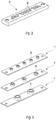
- FIG 3 three removable disks 7 according to the invention are shown as examples.
- the removable plates 7 have a metallic, rectangular base body which is provided with prefabricated through openings 8.
- the interchangeable plates 7 shown here show, by way of example, passage openings 8 with three different radii in order to illustrate that a large number of such interchangeable plates 7 with appropriately prepared passage openings 8 can be kept.
- the removable plates 7 with regard to their dimensions, in particular the edge length of the base support according to the in Figure 2 conventional cable bushing 5 shown in particular are designed according to the dimensions of the base area of the cable bushing 5. This way it becomes possible to get that out Figure 2 known elements against the in Figure 3 to replace shown removable plates 7 or vice versa or to use combinations of the elements shown.
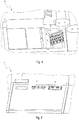
- FIG. 5 Another embodiment is in Figure 5 shown where different removable plates 7 or, if the openings are not in use, so-called dummy plates 7 'are integrated in the flat bottom surface of a distribution cabinet 1.
- FIG 6 shows another advantageous way of making cable routing more flexible in distribution cabinets.
- C-profile rails 9 arranged in the bottom area of a distribution cabinet 1 are shown, on which cross rails 10 for fastening guide elements 11 for
- the transverse rails 10 can be displaced practically continuously along the C-profile rails 9 and thus enable an extremely flexible arrangement of cable routing elements 11.
- FIG 7 an exemplary transverse rail 10 'is shown, which is referred to below as a horizontal rail. It has two fastening tabs 12 with screws for fastening to the C-profile rails 9 mentioned above, as well as a longitudinal slot 13 and a plurality of bores 14, in particular threaded bores.
- the rail 10 ′′ shown is designed as a vertical rail, which runs essentially vertically to the plane formed by the C-profile rails 9. What is common to the rails 10 ′ and 10 ′′ is as shown in FIG Figure 8 It can be seen, the longitudinal slot 13 as well as the threaded holes 14 and the fastening tabs 12. In the Figures 9 to 11 it can be seen what degree of flexibility with regard to the fastening and arrangement of cable guide elements 11 is offered by the modular rail system shown. So is in figure 9 Shown as an example, how hammer head pipe clamps 11 'are connected to a cross rail 10' and can be used for guiding individual cables or bundles of cables.
- the pipe clamps 11 ' can be displaced along the cross rail 10' as well as together with the cross rail along the C-profile rails 9, so that practically every point in the plane formed from the C-profile rails can be approached with a pipe clamp.
- Figure 11 shows a variant in which so-called combs 11 '′′ for guiding tubes, in which cables can even be guided, are fastened to a vertical cross rail 10 ′′ by screwing them into the threaded bores 14.
- combs 11 '′′ for guiding tubes in which cables can even be guided, are fastened to a vertical cross rail 10 ′′ by screwing them into the threaded bores 14.
Landscapes
- Engineering & Computer Science (AREA)
- Power Engineering (AREA)
- Light Guides In General And Applications Therefor (AREA)
- Installation Of Indoor Wiring (AREA)
Claims (8)
- Dispositif de distribution (1) comportant un dispositif permettant le passage ou la fixation de lignes, notamment de tuyaux ou de câbles, dans celui-ci, dans lequel un puits d'entrée en forme de V (4) est conçu dans une surface de paroi du dispositif de distribution (1) et contient au moins un élément de conversion (7, 10) permettant le passage de lignes,
caractérisé en ce que
le dispositif de distribution est une armoire de distribution (1) et la surface de paroi présentant le puits d'entrée en forme de V (4) représente une partie centrale de l'armoire de distribution. - Dispositif de distribution (1) selon la revendication 1,
caractérisé en ce que
l'élément de conversion est conçu sous la forme d'une plaque de conversion (7) et présente, pour le passage de câbles ou de tuyaux, au moins une entrée de passage (8) de rayon défini. - Dispositif de distribution (1) selon la revendication 1,
caractérisé en ce que
l'élément de conversion (10) est conçu, pour la fixation de câbles ou de tuyaux, sous la forme d'un rail transversal (10' et 10") destiné à être fixé dans des rails profilés en C (9). - Dispositif de distribution selon la revendication 3,
caractérisé en ce que
les rails transversaux (10' et 10") sont raccordables aux rails profilés en C (9) par le biais de pattes de fixation (12). - Dispositif de distribution selon la revendication 3 ou 4,
caractérisé en ce que
les rails transversaux (10' et 10") destinés à la fixation de câbles ou de tuyaux présentent une rainure longitudinale (13). - Dispositif de distribution selon l'une quelconque des revendications précédentes 3 à 5,
caractérisé en ce que
les rails transversaux (10' et 10") destinés à la fixation de câbles ou de tuyaux présentent une pluralité de perforations (14), notamment taraudées. - Dispositif de distribution selon l'une quelconque des revendications précédentes 3 à 6,
caractérisé en ce que
les rails transversaux (10' et 10") destinés à la fixation de câbles ou de tuyaux sont conçus verticaux (10") ou horizontaux (10') par rapport au plan formé par les rails profilés en C (9). - Dispositif de distribution selon la revendication 7,
caractérisé en ce que
une zone supérieure (2) et une zone inférieure (3) du dispositif de distribution (1) sont accessibles séparément l'une de l'autre au moyen de portes.
Priority Applications (1)
| Application Number | Priority Date | Filing Date | Title |
|---|---|---|---|
| PL14170870T PL2811594T3 (pl) | 2013-06-03 | 2014-06-03 | Urządzenie do przeprowadzania lub mocowania przewodów w szafie rozdzielczej |
Applications Claiming Priority (1)
| Application Number | Priority Date | Filing Date | Title |
|---|---|---|---|
| DE202013102386U DE202013102386U1 (de) | 2013-06-03 | 2013-06-03 | Vorrichtung zur Durchführung oder Befestigung von Leitungen und Verteilerschrank |
Publications (2)
| Publication Number | Publication Date |
|---|---|
| EP2811594A1 EP2811594A1 (fr) | 2014-12-10 |
| EP2811594B1 true EP2811594B1 (fr) | 2021-02-24 |
Family
ID=48784292
Family Applications (1)
| Application Number | Title | Priority Date | Filing Date |
|---|---|---|---|
| EP14170870.1A Active EP2811594B1 (fr) | 2013-06-03 | 2014-06-03 | Dispositif destiné au passage ou à la fixation de câbles dans une armoire de distribution |
Country Status (4)
| Country | Link |
|---|---|
| EP (1) | EP2811594B1 (fr) |
| DE (1) | DE202013102386U1 (fr) |
| DK (1) | DK2811594T3 (fr) |
| PL (1) | PL2811594T3 (fr) |
Families Citing this family (2)
| Publication number | Priority date | Publication date | Assignee | Title |
|---|---|---|---|---|
| CN106025825A (zh) * | 2016-06-27 | 2016-10-12 | 国网江苏省电力公司盐城供电公司 | 一种防窃电配电柜 |
| WO2019195109A1 (fr) * | 2018-04-04 | 2019-10-10 | Corning Research & Development Corporation | Joint à taille variable et procédé associé |
Citations (2)
| Publication number | Priority date | Publication date | Assignee | Title |
|---|---|---|---|---|
| DE10346742A1 (de) * | 2003-07-25 | 2005-02-17 | Bruno Ehmann | Vorrichtung zum Durchführen von Kabeln oder Leitungen durch Öffnungen |
| WO2005107028A1 (fr) * | 2004-04-30 | 2005-11-10 | Siemens Aktiengesellschaft | Boitier de distributeur d'installation |
Family Cites Families (5)
| Publication number | Priority date | Publication date | Assignee | Title |
|---|---|---|---|---|
| DE7718935U1 (de) * | 1977-06-16 | 1977-09-22 | Karl Pfisterer Elektrotechnische Spezialartikel Gmbh & Co Kg, 7000 Stuttgart | Sockel eines Kabelverteilerschrankes |
| JPH0343765Y2 (fr) * | 1987-06-05 | 1991-09-13 | ||
| DE4207281C1 (fr) * | 1992-03-07 | 1993-04-29 | Rittal-Werk Rudolf Loh Gmbh & Co Kg, 6348 Herborn, De | |
| DE19851952C1 (de) * | 1998-11-11 | 2000-03-30 | Loh Kg Rittal Werk | Schaltschrank mit einer Kabeleinführung |
| DE19961244C1 (de) * | 1999-12-18 | 2001-01-25 | Loh Kg Rittal Werk | Gehäuse |
-
2013
- 2013-06-03 DE DE202013102386U patent/DE202013102386U1/de not_active Expired - Lifetime
-
2014
- 2014-06-03 EP EP14170870.1A patent/EP2811594B1/fr active Active
- 2014-06-03 DK DK14170870.1T patent/DK2811594T3/da active
- 2014-06-03 PL PL14170870T patent/PL2811594T3/pl unknown
Patent Citations (2)
| Publication number | Priority date | Publication date | Assignee | Title |
|---|---|---|---|---|
| DE10346742A1 (de) * | 2003-07-25 | 2005-02-17 | Bruno Ehmann | Vorrichtung zum Durchführen von Kabeln oder Leitungen durch Öffnungen |
| WO2005107028A1 (fr) * | 2004-04-30 | 2005-11-10 | Siemens Aktiengesellschaft | Boitier de distributeur d'installation |
Also Published As
| Publication number | Publication date |
|---|---|
| DK2811594T3 (da) | 2021-05-17 |
| DE202013102386U1 (de) | 2013-06-12 |
| PL2811594T3 (pl) | 2021-08-09 |
| EP2811594A1 (fr) | 2014-12-10 |
Similar Documents
| Publication | Publication Date | Title |
|---|---|---|
| EP2901195B1 (fr) | Dispositif de protection contre les intempéries d'une mise en contact électrique de câble | |
| DE60127760T2 (de) | Glasfaserverteilungssystem | |
| EP2124302A1 (fr) | Baie pour une cellule d'essai | |
| EP3285105B1 (fr) | Distributeur réseau en fibre de verre | |
| EP1336065B1 (fr) | Tete de pied, notamment destinee a un dispositif medical de surveillance et d'alimentation, profile de support pour une telle tete de pied et chariot d'appareils | |
| EP3965240A1 (fr) | Dispositif de fixation et de câblage des unités électriques dans une armoire de distribution | |
| DE202015101776U1 (de) | Rangierwabe | |
| DE102005056215B4 (de) | Vorrichtung zum Führen von Kabeln oder Leitungen | |
| EP2811594A1 (fr) | Dispositif destiné au passage ou à la fixation de câbles dans une armoire de distribution | |
| DE102011053523A1 (de) | Wechselrichter | |
| DE19961244C1 (de) | Gehäuse | |
| DE102015105548A1 (de) | Rangierwabe | |
| EP3217494A1 (fr) | Support pour porter des cables, des câbles préférables à haute tension | |
| DE10325938B4 (de) | Kleinverteiler | |
| CH712434A2 (de) | Verteilermodul mit einer Leitungsführungsanordnung. | |
| DE102008060361B4 (de) | Anordnung zur Führung elektrischer Leitungen | |
| EP4350409B1 (fr) | Ensemble modulaire, unité de support et ensemble support pour la technique de distribution de fibres optiques | |
| EP3499660B1 (fr) | Agencement comprenant un premier et un second rails support, un couvercle et un premier et un second dispositifs support, et boîtier de distribution | |
| DE102015017351B4 (de) | Verteilerschrank | |
| EP2134214B1 (fr) | Système guide-câble | |
| DE202006006183U1 (de) | Möbel | |
| DE2949716C2 (de) | Vorrichtung zum Befestigen der Bündel vonKabeln, mit denen einzelne in einem Gestellschrank angeordnete elektrische Geräte der Mess- oder Nachrichtentechnik elektrisch mit einander verbunden sind | |
| EP4266101A1 (fr) | Armoire de distribution | |
| AT528636A2 (de) | Halterung für ein Kabel in einem Gehäuse, beispielsweise für ein Führungsrohr für Glasfasern in einem Glasfaser-Netzverteiler oder einem Anschlusskasten | |
| WO2005032229A2 (fr) | Structure de base d'un distributeur |
Legal Events
| Date | Code | Title | Description |
|---|---|---|---|
| PUAI | Public reference made under article 153(3) epc to a published international application that has entered the european phase |
Free format text: ORIGINAL CODE: 0009012 |
|
| 17P | Request for examination filed |
Effective date: 20140603 |
|
| AK | Designated contracting states |
Kind code of ref document: A1 Designated state(s): AL AT BE BG CH CY CZ DE DK EE ES FI FR GB GR HR HU IE IS IT LI LT LU LV MC MK MT NL NO PL PT RO RS SE SI SK SM TR |
|
| AX | Request for extension of the european patent |
Extension state: BA ME |
|
| R17P | Request for examination filed (corrected) |
Effective date: 20150520 |
|
| RBV | Designated contracting states (corrected) |
Designated state(s): AL AT BE BG CH CY CZ DE DK EE ES FI FR GB GR HR HU IE IS IT LI LT LU LV MC MK MT NL NO PL PT RO RS SE SI SK SM TR |
|
| RAP1 | Party data changed (applicant data changed or rights of an application transferred) |
Owner name: ZWEICOM GMBH |
|
| RAP1 | Party data changed (applicant data changed or rights of an application transferred) |
Owner name: ZWEICOM-HAUFF GMBH |
|
| STAA | Information on the status of an ep patent application or granted ep patent |
Free format text: STATUS: EXAMINATION IS IN PROGRESS |
|
| 17Q | First examination report despatched |
Effective date: 20180606 |
|
| GRAP | Despatch of communication of intention to grant a patent |
Free format text: ORIGINAL CODE: EPIDOSNIGR1 |
|
| STAA | Information on the status of an ep patent application or granted ep patent |
Free format text: STATUS: GRANT OF PATENT IS INTENDED |
|
| INTG | Intention to grant announced |
Effective date: 20200626 |
|
| GRAJ | Information related to disapproval of communication of intention to grant by the applicant or resumption of examination proceedings by the epo deleted |
Free format text: ORIGINAL CODE: EPIDOSDIGR1 |
|
| STAA | Information on the status of an ep patent application or granted ep patent |
Free format text: STATUS: EXAMINATION IS IN PROGRESS |
|
| GRAP | Despatch of communication of intention to grant a patent |
Free format text: ORIGINAL CODE: EPIDOSNIGR1 |
|
| STAA | Information on the status of an ep patent application or granted ep patent |
Free format text: STATUS: GRANT OF PATENT IS INTENDED |
|
| INTC | Intention to grant announced (deleted) | ||
| INTG | Intention to grant announced |
Effective date: 20201013 |
|
| GRAS | Grant fee paid |
Free format text: ORIGINAL CODE: EPIDOSNIGR3 |
|
| GRAA | (expected) grant |
Free format text: ORIGINAL CODE: 0009210 |
|
| STAA | Information on the status of an ep patent application or granted ep patent |
Free format text: STATUS: THE PATENT HAS BEEN GRANTED |
|
| AK | Designated contracting states |
Kind code of ref document: B1 Designated state(s): AL AT BE BG CH CY CZ DE DK EE ES FI FR GB GR HR HU IE IS IT LI LT LU LV MC MK MT NL NO PL PT RO RS SE SI SK SM TR |
|
| REG | Reference to a national code |
Ref country code: GB Ref legal event code: FG4D Free format text: NOT ENGLISH |
|
| REG | Reference to a national code |
Ref country code: CH Ref legal event code: EP |
|
| REG | Reference to a national code |
Ref country code: DE Ref legal event code: R096 Ref document number: 502014015283 Country of ref document: DE |
|
| REG | Reference to a national code |
Ref country code: AT Ref legal event code: REF Ref document number: 1365682 Country of ref document: AT Kind code of ref document: T Effective date: 20210315 |
|
| REG | Reference to a national code |
Ref country code: IE Ref legal event code: FG4D Free format text: LANGUAGE OF EP DOCUMENT: GERMAN |
|
| REG | Reference to a national code |
Ref country code: CH Ref legal event code: NV Representative=s name: TR-IP CONSULTING LLC, CH |
|
| REG | Reference to a national code |
Ref country code: DK Ref legal event code: T3 Effective date: 20210510 |
|
| REG | Reference to a national code |
Ref country code: SE Ref legal event code: TRGR |
|
| REG | Reference to a national code |
Ref country code: NL Ref legal event code: FP |
|
| REG | Reference to a national code |
Ref country code: GR Ref legal event code: EP Ref document number: 20210401163 Country of ref document: GR Effective date: 20210614 |
|
| REG | Reference to a national code |
Ref country code: LT Ref legal event code: MG9D |
|
| PG25 | Lapsed in a contracting state [announced via postgrant information from national office to epo] |
Ref country code: PT Free format text: LAPSE BECAUSE OF FAILURE TO SUBMIT A TRANSLATION OF THE DESCRIPTION OR TO PAY THE FEE WITHIN THE PRESCRIBED TIME-LIMIT Effective date: 20210624 Ref country code: LT Free format text: LAPSE BECAUSE OF FAILURE TO SUBMIT A TRANSLATION OF THE DESCRIPTION OR TO PAY THE FEE WITHIN THE PRESCRIBED TIME-LIMIT Effective date: 20210224 Ref country code: HR Free format text: LAPSE BECAUSE OF FAILURE TO SUBMIT A TRANSLATION OF THE DESCRIPTION OR TO PAY THE FEE WITHIN THE PRESCRIBED TIME-LIMIT Effective date: 20210224 Ref country code: FI Free format text: LAPSE BECAUSE OF FAILURE TO SUBMIT A TRANSLATION OF THE DESCRIPTION OR TO PAY THE FEE WITHIN THE PRESCRIBED TIME-LIMIT Effective date: 20210224 Ref country code: BG Free format text: LAPSE BECAUSE OF FAILURE TO SUBMIT A TRANSLATION OF THE DESCRIPTION OR TO PAY THE FEE WITHIN THE PRESCRIBED TIME-LIMIT Effective date: 20210524 Ref country code: NO Free format text: LAPSE BECAUSE OF FAILURE TO SUBMIT A TRANSLATION OF THE DESCRIPTION OR TO PAY THE FEE WITHIN THE PRESCRIBED TIME-LIMIT Effective date: 20210524 |
|
| PG25 | Lapsed in a contracting state [announced via postgrant information from national office to epo] |
Ref country code: RS Free format text: LAPSE BECAUSE OF FAILURE TO SUBMIT A TRANSLATION OF THE DESCRIPTION OR TO PAY THE FEE WITHIN THE PRESCRIBED TIME-LIMIT Effective date: 20210224 Ref country code: LV Free format text: LAPSE BECAUSE OF FAILURE TO SUBMIT A TRANSLATION OF THE DESCRIPTION OR TO PAY THE FEE WITHIN THE PRESCRIBED TIME-LIMIT Effective date: 20210224 |
|
| PG25 | Lapsed in a contracting state [announced via postgrant information from national office to epo] |
Ref country code: IS Free format text: LAPSE BECAUSE OF FAILURE TO SUBMIT A TRANSLATION OF THE DESCRIPTION OR TO PAY THE FEE WITHIN THE PRESCRIBED TIME-LIMIT Effective date: 20210624 |
|
| PG25 | Lapsed in a contracting state [announced via postgrant information from national office to epo] |
Ref country code: SM Free format text: LAPSE BECAUSE OF FAILURE TO SUBMIT A TRANSLATION OF THE DESCRIPTION OR TO PAY THE FEE WITHIN THE PRESCRIBED TIME-LIMIT Effective date: 20210224 Ref country code: EE Free format text: LAPSE BECAUSE OF FAILURE TO SUBMIT A TRANSLATION OF THE DESCRIPTION OR TO PAY THE FEE WITHIN THE PRESCRIBED TIME-LIMIT Effective date: 20210224 |
|
| REG | Reference to a national code |
Ref country code: DE Ref legal event code: R097 Ref document number: 502014015283 Country of ref document: DE |
|
| PG25 | Lapsed in a contracting state [announced via postgrant information from national office to epo] |
Ref country code: ES Free format text: LAPSE BECAUSE OF FAILURE TO SUBMIT A TRANSLATION OF THE DESCRIPTION OR TO PAY THE FEE WITHIN THE PRESCRIBED TIME-LIMIT Effective date: 20210224 Ref country code: RO Free format text: LAPSE BECAUSE OF FAILURE TO SUBMIT A TRANSLATION OF THE DESCRIPTION OR TO PAY THE FEE WITHIN THE PRESCRIBED TIME-LIMIT Effective date: 20210224 Ref country code: SK Free format text: LAPSE BECAUSE OF FAILURE TO SUBMIT A TRANSLATION OF THE DESCRIPTION OR TO PAY THE FEE WITHIN THE PRESCRIBED TIME-LIMIT Effective date: 20210224 |
|
| PLBE | No opposition filed within time limit |
Free format text: ORIGINAL CODE: 0009261 |
|
| STAA | Information on the status of an ep patent application or granted ep patent |
Free format text: STATUS: NO OPPOSITION FILED WITHIN TIME LIMIT |
|
| PG25 | Lapsed in a contracting state [announced via postgrant information from national office to epo] |
Ref country code: MC Free format text: LAPSE BECAUSE OF FAILURE TO SUBMIT A TRANSLATION OF THE DESCRIPTION OR TO PAY THE FEE WITHIN THE PRESCRIBED TIME-LIMIT Effective date: 20210224 Ref country code: AL Free format text: LAPSE BECAUSE OF FAILURE TO SUBMIT A TRANSLATION OF THE DESCRIPTION OR TO PAY THE FEE WITHIN THE PRESCRIBED TIME-LIMIT Effective date: 20210224 |
|
| 26N | No opposition filed |
Effective date: 20211125 |
|
| PG25 | Lapsed in a contracting state [announced via postgrant information from national office to epo] |
Ref country code: SI Free format text: LAPSE BECAUSE OF FAILURE TO SUBMIT A TRANSLATION OF THE DESCRIPTION OR TO PAY THE FEE WITHIN THE PRESCRIBED TIME-LIMIT Effective date: 20210224 |
|
| REG | Reference to a national code |
Ref country code: BE Ref legal event code: MM Effective date: 20210630 |
|
| PG25 | Lapsed in a contracting state [announced via postgrant information from national office to epo] |
Ref country code: LU Free format text: LAPSE BECAUSE OF NON-PAYMENT OF DUE FEES Effective date: 20210603 |
|
| PG25 | Lapsed in a contracting state [announced via postgrant information from national office to epo] |
Ref country code: IT Free format text: LAPSE BECAUSE OF FAILURE TO SUBMIT A TRANSLATION OF THE DESCRIPTION OR TO PAY THE FEE WITHIN THE PRESCRIBED TIME-LIMIT Effective date: 20210224 Ref country code: IE Free format text: LAPSE BECAUSE OF NON-PAYMENT OF DUE FEES Effective date: 20210603 |
|
| PG25 | Lapsed in a contracting state [announced via postgrant information from national office to epo] |
Ref country code: IS Free format text: LAPSE BECAUSE OF FAILURE TO SUBMIT A TRANSLATION OF THE DESCRIPTION OR TO PAY THE FEE WITHIN THE PRESCRIBED TIME-LIMIT Effective date: 20210624 Ref country code: FR Free format text: LAPSE BECAUSE OF NON-PAYMENT OF DUE FEES Effective date: 20210630 |
|
| PG25 | Lapsed in a contracting state [announced via postgrant information from national office to epo] |
Ref country code: BE Free format text: LAPSE BECAUSE OF NON-PAYMENT OF DUE FEES Effective date: 20210630 |
|
| REG | Reference to a national code |
Ref country code: NL Ref legal event code: HC Owner name: HAUFF-TECHNIK GRIDCOM GMBH; DE Free format text: DETAILS ASSIGNMENT: CHANGE OF OWNER(S), CHANGE OF OWNER(S) NAME; FORMER OWNER NAME: ZWEICOM-HAUFF GMBH Effective date: 20220803 |
|
| PG25 | Lapsed in a contracting state [announced via postgrant information from national office to epo] |
Ref country code: HU Free format text: LAPSE BECAUSE OF FAILURE TO SUBMIT A TRANSLATION OF THE DESCRIPTION OR TO PAY THE FEE WITHIN THE PRESCRIBED TIME-LIMIT; INVALID AB INITIO Effective date: 20140603 |
|
| P01 | Opt-out of the competence of the unified patent court (upc) registered |
Effective date: 20230512 |
|
| PG25 | Lapsed in a contracting state [announced via postgrant information from national office to epo] |
Ref country code: CY Free format text: LAPSE BECAUSE OF FAILURE TO SUBMIT A TRANSLATION OF THE DESCRIPTION OR TO PAY THE FEE WITHIN THE PRESCRIBED TIME-LIMIT Effective date: 20210224 |
|
| PG25 | Lapsed in a contracting state [announced via postgrant information from national office to epo] |
Ref country code: MK Free format text: LAPSE BECAUSE OF FAILURE TO SUBMIT A TRANSLATION OF THE DESCRIPTION OR TO PAY THE FEE WITHIN THE PRESCRIBED TIME-LIMIT Effective date: 20210224 |
|
| PG25 | Lapsed in a contracting state [announced via postgrant information from national office to epo] |
Ref country code: MT Free format text: LAPSE BECAUSE OF FAILURE TO SUBMIT A TRANSLATION OF THE DESCRIPTION OR TO PAY THE FEE WITHIN THE PRESCRIBED TIME-LIMIT Effective date: 20210224 |
|
| REG | Reference to a national code |
Ref country code: DE Ref legal event code: R082 Ref document number: 502014015283 Country of ref document: DE Representative=s name: SZYNKA SMORODIN PATENTANWAELTE PARTNERSCHAFT M, DE |
|
| PGFP | Annual fee paid to national office [announced via postgrant information from national office to epo] |
Ref country code: PL Payment date: 20250529 Year of fee payment: 12 |
|
| PGFP | Annual fee paid to national office [announced via postgrant information from national office to epo] |
Ref country code: GB Payment date: 20250620 Year of fee payment: 12 Ref country code: DK Payment date: 20250618 Year of fee payment: 12 |
|
| PGFP | Annual fee paid to national office [announced via postgrant information from national office to epo] |
Ref country code: NL Payment date: 20250618 Year of fee payment: 12 |
|
| PGFP | Annual fee paid to national office [announced via postgrant information from national office to epo] |
Ref country code: GR Payment date: 20250616 Year of fee payment: 12 |
|
| PGFP | Annual fee paid to national office [announced via postgrant information from national office to epo] |
Ref country code: TR Payment date: 20250530 Year of fee payment: 12 |
|
| PGFP | Annual fee paid to national office [announced via postgrant information from national office to epo] |
Ref country code: CZ Payment date: 20250526 Year of fee payment: 12 |
|
| PGFP | Annual fee paid to national office [announced via postgrant information from national office to epo] |
Ref country code: SE Payment date: 20250618 Year of fee payment: 12 |
|
| PGFP | Annual fee paid to national office [announced via postgrant information from national office to epo] |
Ref country code: CH Payment date: 20250701 Year of fee payment: 12 |
|
| REG | Reference to a national code |
Ref country code: CH Ref legal event code: R17 Free format text: ST27 STATUS EVENT CODE: U-0-0-R10-R17 (AS PROVIDED BY THE NATIONAL OFFICE) Effective date: 20251024 |
|
| REG | Reference to a national code |
Ref country code: CH Ref legal event code: U11 Free format text: ST27 STATUS EVENT CODE: U-0-0-U10-U11 (AS PROVIDED BY THE NATIONAL OFFICE) Effective date: 20260701 |
|
| PGFP | Annual fee paid to national office [announced via postgrant information from national office to epo] |
Ref country code: DE Payment date: 20260623 Year of fee payment: 13 |
|
| PGFP | Annual fee paid to national office [announced via postgrant information from national office to epo] |
Ref country code: AT Payment date: 20260618 Year of fee payment: 13 |