EP4268905B1 - Trainingsgerät - Google Patents
Trainingsgerät Download PDFInfo
- Publication number
- EP4268905B1 EP4268905B1 EP23170096.4A EP23170096A EP4268905B1 EP 4268905 B1 EP4268905 B1 EP 4268905B1 EP 23170096 A EP23170096 A EP 23170096A EP 4268905 B1 EP4268905 B1 EP 4268905B1
- Authority
- EP
- European Patent Office
- Prior art keywords
- training device
- spring
- spring element
- handle
- range
- Prior art date
- Legal status (The legal status is an assumption and is not a legal conclusion. Google has not performed a legal analysis and makes no representation as to the accuracy of the status listed.)
- Active
Links
Images


Classifications
-
- A—HUMAN NECESSITIES
- A63—SPORTS; GAMES; AMUSEMENTS
- A63B—APPARATUS FOR PHYSICAL TRAINING, GYMNASTICS, SWIMMING, CLIMBING, OR FENCING; BALL GAMES; TRAINING EQUIPMENT
- A63B23/00—Exercising apparatus specially adapted for particular parts of the body
- A63B23/035—Exercising apparatus specially adapted for particular parts of the body for limbs, i.e. upper or lower limbs, e.g. simultaneously
- A63B23/12—Exercising apparatus specially adapted for particular parts of the body for limbs, i.e. upper or lower limbs, e.g. simultaneously for upper limbs or related muscles, e.g. chest, upper back or shoulder muscles
-
- A—HUMAN NECESSITIES
- A63—SPORTS; GAMES; AMUSEMENTS
- A63B—APPARATUS FOR PHYSICAL TRAINING, GYMNASTICS, SWIMMING, CLIMBING, OR FENCING; BALL GAMES; TRAINING EQUIPMENT
- A63B21/00—Exercising apparatus for developing or strengthening the muscles or joints of the body by working against a counterforce, with or without measuring devices
- A63B21/0004—Exercising devices moving as a whole during exercise
-
- A—HUMAN NECESSITIES
- A63—SPORTS; GAMES; AMUSEMENTS
- A63B—APPARATUS FOR PHYSICAL TRAINING, GYMNASTICS, SWIMMING, CLIMBING, OR FENCING; BALL GAMES; TRAINING EQUIPMENT
- A63B21/00—Exercising apparatus for developing or strengthening the muscles or joints of the body by working against a counterforce, with or without measuring devices
- A63B21/02—Exercising apparatus for developing or strengthening the muscles or joints of the body by working against a counterforce, with or without measuring devices using resilient force-resisters
- A63B21/023—Wound springs
-
- A—HUMAN NECESSITIES
- A63—SPORTS; GAMES; AMUSEMENTS
- A63B—APPARATUS FOR PHYSICAL TRAINING, GYMNASTICS, SWIMMING, CLIMBING, OR FENCING; BALL GAMES; TRAINING EQUIPMENT
- A63B21/00—Exercising apparatus for developing or strengthening the muscles or joints of the body by working against a counterforce, with or without measuring devices
- A63B21/02—Exercising apparatus for developing or strengthening the muscles or joints of the body by working against a counterforce, with or without measuring devices using resilient force-resisters
- A63B21/026—Bars; Tubes; Leaf springs
- A63B21/027—Apparatus forced to oscillate at its resonant frequency
-
- A—HUMAN NECESSITIES
- A63—SPORTS; GAMES; AMUSEMENTS
- A63B—APPARATUS FOR PHYSICAL TRAINING, GYMNASTICS, SWIMMING, CLIMBING, OR FENCING; BALL GAMES; TRAINING EQUIPMENT
- A63B23/00—Exercising apparatus specially adapted for particular parts of the body
- A63B23/035—Exercising apparatus specially adapted for particular parts of the body for limbs, i.e. upper or lower limbs, e.g. simultaneously
- A63B23/03508—For a single arm or leg
-
- A—HUMAN NECESSITIES
- A63—SPORTS; GAMES; AMUSEMENTS
- A63B—APPARATUS FOR PHYSICAL TRAINING, GYMNASTICS, SWIMMING, CLIMBING, OR FENCING; BALL GAMES; TRAINING EQUIPMENT
- A63B23/00—Exercising apparatus specially adapted for particular parts of the body
- A63B23/035—Exercising apparatus specially adapted for particular parts of the body for limbs, i.e. upper or lower limbs, e.g. simultaneously
- A63B23/12—Exercising apparatus specially adapted for particular parts of the body for limbs, i.e. upper or lower limbs, e.g. simultaneously for upper limbs or related muscles, e.g. chest, upper back or shoulder muscles
- A63B23/14—Exercising apparatus specially adapted for particular parts of the body for limbs, i.e. upper or lower limbs, e.g. simultaneously for upper limbs or related muscles, e.g. chest, upper back or shoulder muscles for wrist joints
-
- A—HUMAN NECESSITIES
- A63—SPORTS; GAMES; AMUSEMENTS
- A63B—APPARATUS FOR PHYSICAL TRAINING, GYMNASTICS, SWIMMING, CLIMBING, OR FENCING; BALL GAMES; TRAINING EQUIPMENT
- A63B23/00—Exercising apparatus specially adapted for particular parts of the body
- A63B23/035—Exercising apparatus specially adapted for particular parts of the body for limbs, i.e. upper or lower limbs, e.g. simultaneously
- A63B23/12—Exercising apparatus specially adapted for particular parts of the body for limbs, i.e. upper or lower limbs, e.g. simultaneously for upper limbs or related muscles, e.g. chest, upper back or shoulder muscles
- A63B23/16—Exercising apparatus specially adapted for particular parts of the body for limbs, i.e. upper or lower limbs, e.g. simultaneously for upper limbs or related muscles, e.g. chest, upper back or shoulder muscles for hands or fingers
-
- A—HUMAN NECESSITIES
- A63—SPORTS; GAMES; AMUSEMENTS
- A63B—APPARATUS FOR PHYSICAL TRAINING, GYMNASTICS, SWIMMING, CLIMBING, OR FENCING; BALL GAMES; TRAINING EQUIPMENT
- A63B21/00—Exercising apparatus for developing or strengthening the muscles or joints of the body by working against a counterforce, with or without measuring devices
- A63B21/06—User-manipulated weights
- A63B21/072—Dumb-bells, bar-bells or the like, e.g. weight discs having an integral peripheral handle
-
- A—HUMAN NECESSITIES
- A63—SPORTS; GAMES; AMUSEMENTS
- A63B—APPARATUS FOR PHYSICAL TRAINING, GYMNASTICS, SWIMMING, CLIMBING, OR FENCING; BALL GAMES; TRAINING EQUIPMENT
- A63B21/00—Exercising apparatus for developing or strengthening the muscles or joints of the body by working against a counterforce, with or without measuring devices
- A63B21/40—Interfaces with the user related to strength training; Details thereof
- A63B21/4027—Specific exercise interfaces
- A63B21/4033—Handles, pedals, bars or platforms
- A63B21/4035—Handles, pedals, bars or platforms for operation by hand
-
- A—HUMAN NECESSITIES
- A63—SPORTS; GAMES; AMUSEMENTS
- A63B—APPARATUS FOR PHYSICAL TRAINING, GYMNASTICS, SWIMMING, CLIMBING, OR FENCING; BALL GAMES; TRAINING EQUIPMENT
- A63B2220/00—Measuring of physical parameters relating to sporting activity
- A63B2220/80—Special sensors, transducers or devices therefor
- A63B2220/803—Motion sensors
Definitions
- the present invention relates to a handheld training device.
- Hand-held training devices are known in the state of the art in a wide variety of designs. They are normally used to carry out movement and holding exercises in order to strengthen the human body.
- An example of such a training device is a dumbbell comprising a handle element that is designed to be grasped by a single hand of a person and weights positioned at the free ends of the handle element. Further prior art is provided by the publications DE 20 2011 106 952 U1 and US 2,396,106 A .
- the present invention provides a hand-held training device according to claim 1, comprising a handle element that is designed to be grasped by a single hand of a person, and an elongated spring element that protrudes upwards from the handle element, the length and stiffness of which are selected such that the spring element executes a pendulum movement when the handle element is moved slightly.
- the training device according to the invention serves to strengthen both body control and concentration. It is grasped by the handle element with one hand and held in front of the upper body with the arm outstretched. The aim is to keep the training device as still as possible. For control The spring element is used to keep the device steady and is triggered by the smallest of movements.
- the exercise becomes more difficult to perform and increasingly promotes muscle building in the upper body, which is beneficial for good posture.
- the spring element of the training device according to the invention only forms a motion sensor that is easily perceptible by the person doing the training.
- the handle element is preferably made of metal, wood or plastic. The choice of material also largely determines the weight of the handle element.
- the handle element is essentially cylindrical and in particular has a height of 10-15 cm and a diameter in the range of 3-5 cm. In this way, a very simple and inexpensive construction is created.
- the handle element advantageously has recesses for receiving the fingers of a person grasping the handle element, in particular in the form of four circumferential grooves arranged one above the other.
- the handle element can be gripped very comfortably and very securely along such recesses, even with sweaty hands.
- the spring element is preferably made of stainless steel.
- the advantage is that the spring element is difficult to deform, which is beneficial to the longevity of the training device.
- the spring element advantageously has a spring element length in the range of 25 to 45 cm. Accordingly, movements of the spring element can be very easily identified by the person exercising.
- the spring element is inserted into a blind hole provided on the upper side of the handle element and held therein, in particular using a fastening screw, which also serves an inexpensive and easy-to-manufacture structure.
- the spring element is a spiral spring.
- the turns of the spiral spring are preferably close together in the area of the end that is held on the handle element, and the turns have a pitch in the range of 3-8 mm over most of the length of the spiral spring. Thanks to the close-fitting turns, the spiral spring can be easily and securely attached to the handle element.
- the pitch of the turns, which they have over most of the length of the spiral spring ensures that the spiral spring deflects even with the slightest movement of the handle element and that the pendulum movement resulting from the deflection continues for a long time even after the handle element has been held still again.
- the spiral spring is generally preferably selected in such a way that a pendulum movement initiated by a lateral deflection of the spiral spring at the free end by 1 cm only comes to a standstill after 60-120 s when the handle element is held still.
- the spring element advantageously has between 80 and 150 turns.
- the wire diameter is in particular in the range of 1.3 to 1.9 mm.
- the The weight of the spiral spring is preferably in the range of 1 to 8 kg per 100 m of wire length.
- the training device consists of the handle element and the spring element.
- the training device can additionally have just one or more fastening elements for fastening the spring element to the handle element.
- no additional weight is arranged at the free end of the spring element.
- the figures show a handheld training device 1 according to an embodiment of the present invention, which has as main components a handle element 2 and an elongated spring element 3 protruding upwards from the handle element 2.
- the handle element 2 is made of a rust-proof metal.
- the handle element 2 can also be made of wood or plastic. In the present case, it has a substantially cylindrical shape and preferably has a height H in the range of 10 to 15 cm and a diameter D in the range of 3 to 5 cm. In the embodiment shown, the height is approximately 13 cm and the diameter D is approximately 4 cm.
- recesses 4 are provided for receiving the fingers of a person holding the handle element 2, which in the embodiment shown are designed in the form of four circumferential grooves arranged one above the other.
- a blind hole 5 extends in the middle, at the bottom of which a threaded hole 6 is connected.
- the spring element 3 is a spiral spring made of stainless steel, in this case X10CrNi18-8.
- the spring element 3 preferably has a spring element length L 0 in the range of 25 to 45 cm, which in this case is 35 cm.
- the wire diameter d is in the range of 1.3 to 1.9 mm and in this case is 1.6 mm.
- the average diameter D m is preferably in the range of 8 to 12 mm and in this case is 9.8 mm.
- the spring element 3 has in particular between 80 and 150 turns, in this case 110 turns.
- the weight is preferably in the range of 1 to 8 kg per 100 m of wire length and in this case is 6.42 kg per 100 m of wire length.
- the turns of the spiral spring 2 lie close to one another, while over a predominant part of the spiral spring length they have a pitch in the range of preferably 3 to 8 mm, in the present case a pitch of 5 mm.
- the lower end of the spring element 3 is inserted into the blind hole 5 of the handle element 2 and fastened using a fastening screw (not shown in detail) which engages in the threaded hole 6.
- a fastening screw (not shown in detail) which engages in the threaded hole 6.
- other fastening means can also be used. such as adhesive or the like.
- the training device 1 serves to strengthen both body control and concentration. To perform an exercise, the training device 1 is grasped in the handle element 2 with one hand and held in front of the upper body with the arm outstretched. The aim is to keep the training device 1 as still as possible.
- the spring element 3 serves to control the steady holding, which swings out at the slightest movement, whereby the pendulum movement resulting from the swing continues for a longer time even after the handle element 2 is held still again.
- the preferred structure of the spring element 3 described above means that a pendulum movement initiated by a lateral deflection of the spiral spring at the free end by 1 cm only comes to a standstill after 60 to 120 seconds when the handle element 2 is held still.
- the training device 1 does not have a particularly high weight that would place additional strain on the body when the exercise is performed. However, if the handle element 2 is made of metal, the weight of the training device 1 is clearly noticeable, which particularly contributes to strengthening the upper body muscles.
Landscapes
- Health & Medical Sciences (AREA)
- Orthopedic Medicine & Surgery (AREA)
- General Health & Medical Sciences (AREA)
- Physical Education & Sports Medicine (AREA)
- Life Sciences & Earth Sciences (AREA)
- Biophysics (AREA)
- Rehabilitation Tools (AREA)
Description
- Die vorliegende Erfindung betrifft ein handgehaltenes Trainingsgerät.
- Handgehaltene Trainingsgeräte sind im Stand der Technik in unterschiedlichsten Ausgestaltungen bekannt. Mit ihnen werden normalerweise Bewegungs- und Halteübungen durchgeführt, um den menschlichen Körper zu ertüchtigen. Ein Beispiel für ein solches Trainingsgerät ist eine Kurzhantel umfassend ein Griffelement, das dazu ausgelegt ist, von einer einzelnen Hand einer Person gefasst zu werden, und an den freien Enden des Griffelementes positionierte Gewichte. Weiteren Stand der Technik bilden die Druckschriften
DE 20 2011 106 952 U1 undUS 2,396,106 A . - Ausgehend von diesem Stand der Technik ist es eine Aufgabe der vorliegenden Erfindung, ein handgehaltenes Trainingsgerät mit alternativem Aufbau zu schaffen.
- Zur Lösung dieser Aufgabe schafft die vorliegende Erfindung ein handgehaltenes Trainingsgerät gemäß Anspruch 1, umfassend ein Griffelement, das dazu ausgelegt ist von einer einzelnen Hand einer Person gefasst zu werden, und ein aufwärts von dem Griffelement vorstehendes längliches Federelement, dessen Länge und Steifigkeit derart gewählt sind, dass das Federelement bei geringfügiger Bewegung des Griffelementes eine pendelnde Bewegung ausführt. Das erfindungsgemäße Trainingsgerät dient zur Stärkung sowohl der Körperbeherrschung als auch der Konzentration. Es wird am Griffelement mit einer Hand gefasst und mit ausgestrecktem Arm vor dem Oberkörper gehalten. Ziel ist es, das Trainingsgerät so ruhig wie möglich zu halten. Zur Kontrolle des ruhigen Haltens dient das Federelement, das bei kleinsten Bewegungen ausschlägt. Mit steigendem Eigengewicht des Trainingsgerätes, das vornehmlich durch das Eigengewicht des Griffelementes bestimmt wird, wird die Durchführung der Übung erschwert und fördert zunehmend den Muskelaufbau im Oberkörper, was einer guten Körperhaltung zuträglich ist. Im Gegensatz zu herkömmlichen Trainingsgeräten, die über Federelemente verfügen, bildet das Federelement des erfindungsgemäßen Trainingsgerätes ausschließlich einen einfach von der trainierenden Person wahrnehmbaren Bewegungssensor.
- Das Griffelement ist bevorzugt aus Metall, Holz oder Kunststoff hergestellt. Die Wahl des Materials bestimmt auch maßgeblich das Eigengewicht des Griffelementes.
- Gemäß einer Ausführungsform der folgenden Erfindung ist das Griffelement im Wesentlichen zylindrisch und weist insbesondere eine Höhe von 10-15 cm und einen Durchmesser im Bereich von 3-5 cm auf. Auf diese Weise wird ein sehr einfacher und preiswert herzustellender Aufbau geschaffen.
- Das Griffelement weist vorteilhaft Vertiefungen zur Aufnahme der Finger einer das Griffelement fassenden Person auf, insbesondere in Form von vier übereinander angeordneten Umfangsnuten. Entlang solcher Vertiefungen lässt sich das Griffelement sehr angenehm und auch mit verschwitzten Händen sehr sicher fassen.
- Das Federelement ist bevorzugt aus rostfreiem Stahl hergestellt. Der Vorteil besteht darin, dass sich das Federelement nur schwer verformen lässt, was der Langlebigkeit des Trainingsgeräts zuträglich ist.
- Vorteilhaft weist das Federelement eine Federelementlänge im Bereich von 25 bis 45 cm auf. Entsprechend lassen sich Bewegungen des Federelementes sehr leicht von der trainierenden Person identifizieren.
- Bevorzugt ist das Federelement in ein an der Oberseite des Griffelementes vorgesehenes Sackloch eingeschoben und darin gehalten, insbesondere unter Verwendung einer Befestigungsschraube, was ebenfalls einem preiswerten und einfach herzustellenden Aufbau dient.
- Gemäß einer Ausgestaltung der vorliegenden Erfindung handelt es sich bei dem Federelement um eine Spiralfeder.
- Die Windungen der Spiralfeder liegen im Bereich desjenigen Endes, das an dem Griffelement gehalten ist, bevorzugt dicht aneinander an, und die Windungen weisen über einen überwiegenden Teil der Spiralfederlänge eine Steigung im Bereich von 3-8 mm auf. Dank der dicht aneinander anliegenden Windungen lässt sich die Spiralfeder einfach und sicher am Griffelement befestigen. Die genannte Steigung der Windungen, die diese über den überwiegenden Teil der Spiralfederlänge aufweisen, stellt sicher, dass die Spiralfeder bereits bei geringsten Bewegungen des Griffelementes ausschlägt und die durch den Ausschlag resultierende Pendelbewegung auch nach erneutem Ruhighalten des Griffelementes noch eine längere Zeit anhält. Diesbezüglich ist die Spiralfeder grundsätzlich bevorzugt derart gewählt, dass eine Pendelbewegung, die durch eine seitliche Auslenkung der Spiralfeder am freien Ende um 1 cm initiiert wird, bei ruhig gehaltenem Griffelement insbesondere erst nach 60-120 s zum Stillstand kommt.
- Das Federelement weist vorteilhaft zwischen 80 und 150 Windungen auf. Der Drahtdurchmesser liegt insbesondere im Bereich von 1,3 bis 1,9 mm. Das Gewicht der Spiralfeder liegt bevorzugt im Bereich von 1 bis 8 kg pro 100 m Drahtlänge.
- Erfindungsgemäß besteht das Trainingsgerät aus dem Griffelement und dem Federelement. Optional kann das Trainingsgerät zusätzlich lediglich ein oder mehrere Befestigungselemente zum Befestigen des Federelementes an dem Griffelement aufweisen. Insbesondere ist am freien Ende des Federelementes kein zusätzliches Gewicht angeordnet.
- Weitere Merkmale und Vorteile der vorliegenden Erfindung werden anhand der nachfolgenden Beschreibung einer Ausführungsform eines erfindungsgemäßen Trainingsgeräts unter Bezugnahme auf die beiliegende Zeichnung deutlich. Darin ist
-
Figur 1 eine Vorderansicht eines Trainingsgeräts gemäß einer Ausführungsform der vorliegenden Erfindung; -
Figur 2 eine teilweise geschnittene Vorderansicht eines Griffelementes des inFigur 1 gezeigten Trainingsgeräts. -
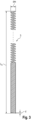
Figur 3 eine Vorderansicht eines Federelementes des inFigur 1 gezeigten Trainingsgeräts und - Die Figuren zeigen ein handgehaltenes Trainingsgerät 1 gemäß einer Ausführungsform der vorliegenden Erfindung, dass als Hauptkomponenten ein Griffelement 2 sowie ein aufwärts von dem Griffelement 2 vorstehendes längliches Federelement 3 aufweist.
- Das Griffelement 2 ist vorliegend aus einem rostfreien Metall hergestellt. Alternativ kann das Griffelement 2 aber auch aus Holz oder Kunststoff gefertigt sein. Es hat vorliegend eine im Wesentlichen zylindrische Form und weist bevorzugt eine Höhe H im Bereich von 10 bis 15 cm und einen Durchmesser D im Bereich von 3 bis 5 cm auf. Bei der dargestellten Ausführungsform beträgt die Höhe etwa 13 cm und der Durchmesser D etwa 4 cm. Am Außenumfang des Griffelementes 2 sind Vertiefungen 4 zur Aufnahme der Finger einer das Griffelement 2 umfassenden Person vorgesehen, welche bei der dargestellten Ausführungsform in Form von vier übereinander angeordneten Umfangsnuten ausgebildet sind. Ausgehend von der Oberseite des Griffelementes 2 erstreckt sich mittig ein Sackloch 5, an dessen Boden sich eine Gewindebohrung 6 anschließt.
- Bei dem Federelement 3 handelt es sich vorliegend um eine Spiralfeder, die aus rostfreiem Edelstahl gefertigt ist, vorliegend aus X10CrNi18-8. Das Federelement 3 weist im ungespannten Zustand bevorzugt eine Federelementlänge L0 im Bereich von 25 bis 45 cm auf, die vorliegend 35 cm beträgt. Der Drahtdurchmesser d liegt vorliegend im Bereich von 1,3 bis 1,9 mm und beträgt vorliegend 1,6 mm. Der mittlere Durchmesser Dm liegt bevorzugt im Bereich von 8 bis 12 mm und beträgt vorliegend 9,8 mm. Das Federelement 3 weist insbesondere zwischen 80 und 150 Windungen auf, vorliegend 110 Windungen. Das Gewicht liegt bevorzugt im Bereich von 1 bis 8 kg pro 100 m Drahtlänge und beträgt vorliegend 6,42 kg pro 100 m Drahtlänge. Im Bereich des unteren Endes liegen die Windungen der Spiralfeder 2 dicht aneinander an, während sie über einen überwiegenden Teil der Spiralfederlänge eine Steigung im Bereich von bevorzugt 3 bis 8 mm aufweisen, auf vorliegend eine Steigung von 5 mm.
- Wie es in
Figur 1 dargestellt ist, ist das untere Ende des Federelementes 3 in das Sackloch 5 des Griffelementes 2 eingeführt und unter Verwendung einer nicht näher dargestellten Befestigungsschraube, die in die Gewindebohrung 6 greift, befestigt. Alternativ oder zusätzlich können auch andere Befestigungsmittel eingesetzt werden, wie beispielsweise Klebstoff oder dergleichen. - Das erfindungsgemäße Trainingsgerät 1 dient zur Stärkung sowohl der Körperbeherrschung als auch der Konzentration. Zur Durchführung einer Übung wird das Trainingsgerät 1 im Griffelement 2 mit einer Hand gefasst und mit ausgestrecktem Arm vor dem Oberkörper gehalten. Ziel ist es, das Trainingsgerät 1 so ruhig wie möglich zu halten. Zur Kontrolle des ruhigen Haltens dient das Federelement 3, das bei kleinsten Bewegungen ausschlägt, wobei die durch den Ausschlag resultierende Pendelbewegung auch nach erneutem Ruhighalten des Griffelementes 2 noch eine längere Zeit anhält. Der vorbeschriebene bevorzugte Aufbau des Federelementes 3 führt dazu, dass eine Pendelbewegung, die durch eine seitliche Auslenkung der Spiralfeder am freien Ende um 1 cm initiiert wird, bei ruhig gehaltenem Griffelement 2 insbesondere erst nach 60 bis 120 Sekunden zum Stillstand kommt. Ist das Griffelement 2 aus Holz oder Kunststoff gefertigt, so weist das Trainingsgerät 1 kein besonders hohes Eigengewicht auf, das den Körper bei Durchführung der Übung zusätzlich belastet. Ist das Griffelement 2 jedoch aus Metall hergestellt, so ist das Eigengewicht des Trainingsgerätes 1 deutlich spürbar, was insbesondere zur Stärkung der Oberkörpermuskulatur beiträgt.
- Es sollte klar sein, dass die vorbeschriebene Ausführungsform nur als Beispiel dient und nicht als einschränkend verstanden werden soll. Vielmehr sind Modifikation und Änderungen möglich, ohne den durch die beiliegenden Ansprüche definierten Schutzbereich zu verlassen.
-
- 1
- Trainingsgerät
- 2
- Griffelement
- 3
- Federelement
- 4
- Vertiefung
- 5
- Sackloch
- 6
- Gewindebohrung
- H
- Höhe
- D
- Durchmesser
- L0
- ungespannte Länge der Feder
- d
- Drahtdurchmesser
- dm
- mittlerer Durchmesser
Claims (10)
- Handgehaltenes Trainingsgerät (1) umfassend ein Griffelement (2), das dazu ausgelegt ist, von einer einzelnen Hand einer Person gefasst zu werden, und ein aufwärts von dem Griffelement (2) vorstehendes längliches Federelement (3), dessen Länge und Steifigkeit derart gewählt sind, dass das Federelement (3) bei geringfügiger Bewegung des Griffelementes (2) eine pendelnde Bewegung ausführt, dadurch gekennzeichnet, dass das Trainingsgerät (1) aus dem Griffelement (2) und dem Federelement (3) besteht, optional zusätzlich aus einem oder mehreren Befestigungselementen zum Befestigen des Federelementes (3) an dem Griffelement (2).
- Trainingsgerät (1) nach Anspruch 1, dadurch gekennzeichnet, dass das Griffelement (2) aus Metall, Holz oder Kunststoff hergestellt ist.
- Trainingsgerät (1) nach Anspruch 1 oder 2, dadurch gekennzeichnet, dass das Griffelement (2) im Wesentlichen zylindrisch ist und insbesondere eine Höhe (H) im Bereich von 10-15 cm und einen Durchmesser (D) im Bereich von 3-5 cm aufweist.
- Trainingsgerät (1) nach Anspruch einem der vorhergehenden Ansprüche, dadurch gekennzeichnet, dass das Griffelement (2) Vertiefungen (4) zur Aufnahme der Finger einer das Griffelement (2) fassenden Person aufweist, insbesondere in Form von vier übereinander angeordneten Umfangsnuten.
- Trainingsgerät (1) nach einem der vorhergehenden Ansprüche, dadurch gekennzeichnet, dass das Federelement (3) aus rostfreiem Stahl hergestellt ist.
- Trainingsgerät (1) nach einem der vorhergehenden Ansprüche, dadurch gekennzeichnet, dass das Federelement (3) eine Federelementlänge (L0) im Bereich von 25-45 cm aufweist.
- Trainingsgerät (1) nach einem der vorhergehenden Ansprüche, dadurch gekennzeichnet, dass das Federelement (3) in ein an der Oberseite des Griffelementes (3) vorgesehenes Sackloch (5) eingeschoben und darin gehalten ist, insbesondere unter Verwendung einer Befestigungsschraube.
- Trainingsgerät (1) nach einem der vorhergehenden Ansprüche, dadurch gekennzeichnet, dass es sich bei dem Federelement (3) um eine Spiralfeder handelt.
- Trainingsgerät (1) nach Anspruch 8, dadurch gekennzeichnet, dass die Windungen des Federelementes (3) im Bereich desjenigen Endes, das an dem Griffelement (3) gehalten ist, dicht aneinander anliegen, und die Windungen über einen überwiegenden Teil der Spiralfederlänge (L0) eine Steigung im Bereich von 3-8 mm aufweisen.
- Trainingsgerät (1) nach Anspruch 8 oder 9, dadurch gekennzeichnet, dass das Federelement (3) zwischen 80 und 150 Windungen aufweist und/oder der Drahtdurchmesser (d) im Bereich von 1,3-1,9 mm liegt und/oder das Gewicht im Bereich von 1-8 kg pro 100 m Drahtlänge liegt.
Applications Claiming Priority (1)
| Application Number | Priority Date | Filing Date | Title |
|---|---|---|---|
| DE202022102341.7U DE202022102341U1 (de) | 2022-04-29 | 2022-04-29 | Trainingsgerät |
Publications (3)
| Publication Number | Publication Date |
|---|---|
| EP4268905A1 EP4268905A1 (de) | 2023-11-01 |
| EP4268905C0 EP4268905C0 (de) | 2024-09-18 |
| EP4268905B1 true EP4268905B1 (de) | 2024-09-18 |
Family
ID=82217813
Family Applications (1)
| Application Number | Title | Priority Date | Filing Date |
|---|---|---|---|
| EP23170096.4A Active EP4268905B1 (de) | 2022-04-29 | 2023-04-26 | Trainingsgerät |
Country Status (2)
| Country | Link |
|---|---|
| EP (1) | EP4268905B1 (de) |
| DE (1) | DE202022102341U1 (de) |
Family Cites Families (2)
| Publication number | Priority date | Publication date | Assignee | Title |
|---|---|---|---|---|
| US2396106A (en) * | 1944-01-29 | 1946-03-05 | Phillip S Kussnir | Exercising device |
| DE202011106952U1 (de) * | 2011-10-20 | 2012-10-25 | Gwendolin Weinbrecht | Trainingsgerät zum Training der oberen Extremitäten |
-
2022
- 2022-04-29 DE DE202022102341.7U patent/DE202022102341U1/de active Active
-
2023
- 2023-04-26 EP EP23170096.4A patent/EP4268905B1/de active Active
Also Published As
| Publication number | Publication date |
|---|---|
| EP4268905C0 (de) | 2024-09-18 |
| DE202022102341U1 (de) | 2022-06-10 |
| EP4268905A1 (de) | 2023-11-01 |
Similar Documents
| Publication | Publication Date | Title |
|---|---|---|
| DE10127319B4 (de) | Wellnessgerät | |
| EP2252471B1 (de) | Stift | |
| DE102016103072A1 (de) | Trampolin | |
| EP2909078B1 (de) | Gefederter fahrradhandgriff | |
| EP0195288A2 (de) | Gymnastikgerät | |
| DE19733805A1 (de) | Schwimm- und/oder Gymnastiksystem | |
| EP4268905B1 (de) | Trainingsgerät | |
| DE3700072C1 (de) | Ballspielschlaeger,insbesondere Badmintonschlaeger | |
| EP1338308A1 (de) | Gymnastikstab | |
| EP4087667B1 (de) | Handstand-trainingsvorrichtung | |
| DE202008012928U1 (de) | Gerät | |
| DE202011106952U1 (de) | Trainingsgerät zum Training der oberen Extremitäten | |
| DE20203274U1 (de) | Trainingsgerät | |
| DE202009013102U1 (de) | Golfschläger | |
| DE2612683A1 (de) | Schlagwerkzeug | |
| DE8708336U1 (de) | Gymnastik-Gerät | |
| DE1070974B (de) | ||
| DE1144164B (de) | Der Staerkung der Hand- und Armmuskeln dienendes UEbungsgeraet | |
| DE202006004951U1 (de) | Übungshilfe für Schlagzeuger | |
| DE8526649U1 (de) | Trainingsvorrichtung | |
| DE20307359U1 (de) | Gymnastikkeule mit variierbarem Gewicht | |
| DE8034654U1 (de) | Skiflügel | |
| DE102009053841A1 (de) | Bownee | |
| DE7333231U (de) | Trimmgerät | |
| DE202016101606U1 (de) | Gerät |
Legal Events
| Date | Code | Title | Description |
|---|---|---|---|
| PUAI | Public reference made under article 153(3) epc to a published international application that has entered the european phase |
Free format text: ORIGINAL CODE: 0009012 |
|
| STAA | Information on the status of an ep patent application or granted ep patent |
Free format text: STATUS: THE APPLICATION HAS BEEN PUBLISHED |
|
| AK | Designated contracting states |
Kind code of ref document: A1 Designated state(s): AL AT BE BG CH CY CZ DE DK EE ES FI FR GB GR HR HU IE IS IT LI LT LU LV MC ME MK MT NL NO PL PT RO RS SE SI SK SM TR |
|
| STAA | Information on the status of an ep patent application or granted ep patent |
Free format text: STATUS: REQUEST FOR EXAMINATION WAS MADE |
|
| 17P | Request for examination filed |
Effective date: 20240315 |
|
| RBV | Designated contracting states (corrected) |
Designated state(s): AL AT BE BG CH CY CZ DE DK EE ES FI FR GB GR HR HU IE IS IT LI LT LU LV MC ME MK MT NL NO PL PT RO RS SE SI SK SM TR |
|
| GRAP | Despatch of communication of intention to grant a patent |
Free format text: ORIGINAL CODE: EPIDOSNIGR1 |
|
| STAA | Information on the status of an ep patent application or granted ep patent |
Free format text: STATUS: GRANT OF PATENT IS INTENDED |
|
| INTG | Intention to grant announced |
Effective date: 20240627 |
|
| GRAS | Grant fee paid |
Free format text: ORIGINAL CODE: EPIDOSNIGR3 |
|
| GRAA | (expected) grant |
Free format text: ORIGINAL CODE: 0009210 |
|
| STAA | Information on the status of an ep patent application or granted ep patent |
Free format text: STATUS: THE PATENT HAS BEEN GRANTED |
|
| AK | Designated contracting states |
Kind code of ref document: B1 Designated state(s): AL AT BE BG CH CY CZ DE DK EE ES FI FR GB GR HR HU IE IS IT LI LT LU LV MC ME MK MT NL NO PL PT RO RS SE SI SK SM TR |
|
| REG | Reference to a national code |
Ref country code: GB Ref legal event code: FG4D Free format text: NOT ENGLISH |
|
| REG | Reference to a national code |
Ref country code: CH Ref legal event code: EP |
|
| REG | Reference to a national code |
Ref country code: IE Ref legal event code: FG4D Free format text: LANGUAGE OF EP DOCUMENT: GERMAN |
|
| REG | Reference to a national code |
Ref country code: DE Ref legal event code: R096 Ref document number: 502023000178 Country of ref document: DE |
|
| U01 | Request for unitary effect filed |
Effective date: 20241004 |
|
| U07 | Unitary effect registered |
Designated state(s): AT BE BG DE DK EE FI FR IT LT LU LV MT NL PT RO SE SI Effective date: 20241016 |
|
| PG25 | Lapsed in a contracting state [announced via postgrant information from national office to epo] |
Ref country code: NO Free format text: LAPSE BECAUSE OF FAILURE TO SUBMIT A TRANSLATION OF THE DESCRIPTION OR TO PAY THE FEE WITHIN THE PRESCRIBED TIME-LIMIT Effective date: 20241218 |
|
| PG25 | Lapsed in a contracting state [announced via postgrant information from national office to epo] |
Ref country code: GR Free format text: LAPSE BECAUSE OF FAILURE TO SUBMIT A TRANSLATION OF THE DESCRIPTION OR TO PAY THE FEE WITHIN THE PRESCRIBED TIME-LIMIT Effective date: 20241219 |
|
| PG25 | Lapsed in a contracting state [announced via postgrant information from national office to epo] |
Ref country code: HR Free format text: LAPSE BECAUSE OF FAILURE TO SUBMIT A TRANSLATION OF THE DESCRIPTION OR TO PAY THE FEE WITHIN THE PRESCRIBED TIME-LIMIT Effective date: 20240918 |
|
| PG25 | Lapsed in a contracting state [announced via postgrant information from national office to epo] |
Ref country code: RS Free format text: LAPSE BECAUSE OF FAILURE TO SUBMIT A TRANSLATION OF THE DESCRIPTION OR TO PAY THE FEE WITHIN THE PRESCRIBED TIME-LIMIT Effective date: 20241218 |
|
| PG25 | Lapsed in a contracting state [announced via postgrant information from national office to epo] |
Ref country code: RS Free format text: LAPSE BECAUSE OF FAILURE TO SUBMIT A TRANSLATION OF THE DESCRIPTION OR TO PAY THE FEE WITHIN THE PRESCRIBED TIME-LIMIT Effective date: 20241218 Ref country code: NO Free format text: LAPSE BECAUSE OF FAILURE TO SUBMIT A TRANSLATION OF THE DESCRIPTION OR TO PAY THE FEE WITHIN THE PRESCRIBED TIME-LIMIT Effective date: 20241218 Ref country code: HR Free format text: LAPSE BECAUSE OF FAILURE TO SUBMIT A TRANSLATION OF THE DESCRIPTION OR TO PAY THE FEE WITHIN THE PRESCRIBED TIME-LIMIT Effective date: 20240918 Ref country code: GR Free format text: LAPSE BECAUSE OF FAILURE TO SUBMIT A TRANSLATION OF THE DESCRIPTION OR TO PAY THE FEE WITHIN THE PRESCRIBED TIME-LIMIT Effective date: 20241219 |
|
| PG25 | Lapsed in a contracting state [announced via postgrant information from national office to epo] |
Ref country code: IS Free format text: LAPSE BECAUSE OF FAILURE TO SUBMIT A TRANSLATION OF THE DESCRIPTION OR TO PAY THE FEE WITHIN THE PRESCRIBED TIME-LIMIT Effective date: 20250118 |
|
| PG25 | Lapsed in a contracting state [announced via postgrant information from national office to epo] |
Ref country code: SM Free format text: LAPSE BECAUSE OF FAILURE TO SUBMIT A TRANSLATION OF THE DESCRIPTION OR TO PAY THE FEE WITHIN THE PRESCRIBED TIME-LIMIT Effective date: 20240918 |
|
| U20 | Renewal fee for the european patent with unitary effect paid |
Year of fee payment: 3 Effective date: 20250311 |
|
| PG25 | Lapsed in a contracting state [announced via postgrant information from national office to epo] |
Ref country code: ES Free format text: LAPSE BECAUSE OF FAILURE TO SUBMIT A TRANSLATION OF THE DESCRIPTION OR TO PAY THE FEE WITHIN THE PRESCRIBED TIME-LIMIT Effective date: 20240918 |
|
| PG25 | Lapsed in a contracting state [announced via postgrant information from national office to epo] |
Ref country code: CZ Free format text: LAPSE BECAUSE OF FAILURE TO SUBMIT A TRANSLATION OF THE DESCRIPTION OR TO PAY THE FEE WITHIN THE PRESCRIBED TIME-LIMIT Effective date: 20240918 Ref country code: PL Free format text: LAPSE BECAUSE OF FAILURE TO SUBMIT A TRANSLATION OF THE DESCRIPTION OR TO PAY THE FEE WITHIN THE PRESCRIBED TIME-LIMIT Effective date: 20240918 |
|
| PG25 | Lapsed in a contracting state [announced via postgrant information from national office to epo] |
Ref country code: SK Free format text: LAPSE BECAUSE OF FAILURE TO SUBMIT A TRANSLATION OF THE DESCRIPTION OR TO PAY THE FEE WITHIN THE PRESCRIBED TIME-LIMIT Effective date: 20240918 |
|
| PLBE | No opposition filed within time limit |
Free format text: ORIGINAL CODE: 0009261 |
|
| STAA | Information on the status of an ep patent application or granted ep patent |
Free format text: STATUS: NO OPPOSITION FILED WITHIN TIME LIMIT |
|
| 26N | No opposition filed |
Effective date: 20250619 |
|
| PG25 | Lapsed in a contracting state [announced via postgrant information from national office to epo] |
Ref country code: MC Free format text: LAPSE BECAUSE OF FAILURE TO SUBMIT A TRANSLATION OF THE DESCRIPTION OR TO PAY THE FEE WITHIN THE PRESCRIBED TIME-LIMIT Effective date: 20240918 |
|
| U20 | Renewal fee for the european patent with unitary effect paid |
Year of fee payment: 4 Effective date: 20260211 |
|
| PG25 | Lapsed in a contracting state [announced via postgrant information from national office to epo] |
Ref country code: IE Free format text: LAPSE BECAUSE OF NON-PAYMENT OF DUE FEES Effective date: 20250426 |