EP4272983A1 - Système de précharge de ressort - Google Patents
Système de précharge de ressort Download PDFInfo
- Publication number
- EP4272983A1 EP4272983A1 EP23172168.9A EP23172168A EP4272983A1 EP 4272983 A1 EP4272983 A1 EP 4272983A1 EP 23172168 A EP23172168 A EP 23172168A EP 4272983 A1 EP4272983 A1 EP 4272983A1
- Authority
- EP
- European Patent Office
- Prior art keywords
- preload
- cylinder
- spring
- valve
- compression
- Prior art date
- Legal status (The legal status is an assumption and is not a legal conclusion. Google has not performed a legal analysis and makes no representation as to the accuracy of the status listed.)
- Pending
Links
Images





Classifications
-
- B—PERFORMING OPERATIONS; TRANSPORTING
- B60—VEHICLES IN GENERAL
- B60G—VEHICLE SUSPENSION ARRANGEMENTS
- B60G15/00—Resilient suspensions characterised by arrangement, location or type of combined spring and vibration damper, e.g. telescopic type
- B60G15/08—Resilient suspensions characterised by arrangement, location or type of combined spring and vibration damper, e.g. telescopic type having fluid spring
- B60G15/12—Resilient suspensions characterised by arrangement, location or type of combined spring and vibration damper, e.g. telescopic type having fluid spring and fluid damper
-
- B—PERFORMING OPERATIONS; TRANSPORTING
- B60—VEHICLES IN GENERAL
- B60G—VEHICLE SUSPENSION ARRANGEMENTS
- B60G15/00—Resilient suspensions characterised by arrangement, location or type of combined spring and vibration damper, e.g. telescopic type
- B60G15/02—Resilient suspensions characterised by arrangement, location or type of combined spring and vibration damper, e.g. telescopic type having mechanical spring
- B60G15/06—Resilient suspensions characterised by arrangement, location or type of combined spring and vibration damper, e.g. telescopic type having mechanical spring and fluid damper
- B60G15/062—Resilient suspensions characterised by arrangement, location or type of combined spring and vibration damper, e.g. telescopic type having mechanical spring and fluid damper the spring being arranged around the damper
-
- B—PERFORMING OPERATIONS; TRANSPORTING
- B60—VEHICLES IN GENERAL
- B60G—VEHICLE SUSPENSION ARRANGEMENTS
- B60G15/00—Resilient suspensions characterised by arrangement, location or type of combined spring and vibration damper, e.g. telescopic type
- B60G15/02—Resilient suspensions characterised by arrangement, location or type of combined spring and vibration damper, e.g. telescopic type having mechanical spring
- B60G15/06—Resilient suspensions characterised by arrangement, location or type of combined spring and vibration damper, e.g. telescopic type having mechanical spring and fluid damper
- B60G15/062—Resilient suspensions characterised by arrangement, location or type of combined spring and vibration damper, e.g. telescopic type having mechanical spring and fluid damper the spring being arranged around the damper
- B60G15/066—Resilient suspensions characterised by arrangement, location or type of combined spring and vibration damper, e.g. telescopic type having mechanical spring and fluid damper the spring being arranged around the damper the spring being different from a coil spring
-
- B—PERFORMING OPERATIONS; TRANSPORTING
- B60—VEHICLES IN GENERAL
- B60G—VEHICLE SUSPENSION ARRANGEMENTS
- B60G17/00—Resilient suspensions having means for adjusting the spring or vibration-damper characteristics, for regulating the distance between a supporting surface and a sprung part of vehicle or for locking suspension during use to meet varying vehicular or surface conditions, e.g. due to speed or load
- B60G17/02—Spring characteristics, e.g. mechanical springs and mechanical adjusting means
- B60G17/021—Spring characteristics, e.g. mechanical springs and mechanical adjusting means the mechanical spring being a coil spring
-
- B—PERFORMING OPERATIONS; TRANSPORTING
- B60—VEHICLES IN GENERAL
- B60G—VEHICLE SUSPENSION ARRANGEMENTS
- B60G17/00—Resilient suspensions having means for adjusting the spring or vibration-damper characteristics, for regulating the distance between a supporting surface and a sprung part of vehicle or for locking suspension during use to meet varying vehicular or surface conditions, e.g. due to speed or load
- B60G17/02—Spring characteristics, e.g. mechanical springs and mechanical adjusting means
- B60G17/027—Mechanical springs regulated by fluid means
- B60G17/0272—Mechanical springs regulated by fluid means the mechanical spring being a coil spring
-
- B—PERFORMING OPERATIONS; TRANSPORTING
- B60—VEHICLES IN GENERAL
- B60G—VEHICLE SUSPENSION ARRANGEMENTS
- B60G17/00—Resilient suspensions having means for adjusting the spring or vibration-damper characteristics, for regulating the distance between a supporting surface and a sprung part of vehicle or for locking suspension during use to meet varying vehicular or surface conditions, e.g. due to speed or load
- B60G17/02—Spring characteristics, e.g. mechanical springs and mechanical adjusting means
- B60G17/04—Spring characteristics, e.g. mechanical springs and mechanical adjusting means fluid spring characteristics
- B60G17/044—Self-pumping fluid springs
-
- B—PERFORMING OPERATIONS; TRANSPORTING
- B60—VEHICLES IN GENERAL
- B60G—VEHICLE SUSPENSION ARRANGEMENTS
- B60G2202/00—Indexing codes relating to the type of spring, damper or actuator
- B60G2202/10—Type of spring
- B60G2202/12—Wound spring
-
- B—PERFORMING OPERATIONS; TRANSPORTING
- B60—VEHICLES IN GENERAL
- B60G—VEHICLE SUSPENSION ARRANGEMENTS
- B60G2202/00—Indexing codes relating to the type of spring, damper or actuator
- B60G2202/10—Type of spring
- B60G2202/15—Fluid spring
- B60G2202/154—Fluid spring with an accumulator
-
- B—PERFORMING OPERATIONS; TRANSPORTING
- B60—VEHICLES IN GENERAL
- B60G—VEHICLE SUSPENSION ARRANGEMENTS
- B60G2202/00—Indexing codes relating to the type of spring, damper or actuator
- B60G2202/20—Type of damper
- B60G2202/24—Fluid damper
-
- B—PERFORMING OPERATIONS; TRANSPORTING
- B60—VEHICLES IN GENERAL
- B60G—VEHICLE SUSPENSION ARRANGEMENTS
- B60G2202/00—Indexing codes relating to the type of spring, damper or actuator
- B60G2202/20—Type of damper
- B60G2202/24—Fluid damper
- B60G2202/242—Pneumatic damper
-
- B—PERFORMING OPERATIONS; TRANSPORTING
- B60—VEHICLES IN GENERAL
- B60G—VEHICLE SUSPENSION ARRANGEMENTS
- B60G2202/00—Indexing codes relating to the type of spring, damper or actuator
- B60G2202/30—Spring/Damper and/or actuator Units
- B60G2202/31—Spring/Damper and/or actuator Units with the spring arranged around the damper, e.g. MacPherson strut
- B60G2202/312—The spring being a wound spring
-
- B—PERFORMING OPERATIONS; TRANSPORTING
- B60—VEHICLES IN GENERAL
- B60G—VEHICLE SUSPENSION ARRANGEMENTS
- B60G2202/00—Indexing codes relating to the type of spring, damper or actuator
- B60G2202/30—Spring/Damper and/or actuator Units
- B60G2202/32—The spring being in series with the damper and/or actuator
- B60G2202/322—The spring being in series with the damper and/or actuator the damper being controllable
-
- B—PERFORMING OPERATIONS; TRANSPORTING
- B60—VEHICLES IN GENERAL
- B60G—VEHICLE SUSPENSION ARRANGEMENTS
- B60G2500/00—Indexing codes relating to the regulated action or device
- B60G2500/10—Damping action or damper
- B60G2500/11—Damping valves
- B60G2500/114—Damping valves pressure regulating valves
-
- B—PERFORMING OPERATIONS; TRANSPORTING
- B60—VEHICLES IN GENERAL
- B60G—VEHICLE SUSPENSION ARRANGEMENTS
- B60G2500/00—Indexing codes relating to the regulated action or device
- B60G2500/20—Spring action or springs
-
- B—PERFORMING OPERATIONS; TRANSPORTING
- B62—LAND VEHICLES FOR TRAVELLING OTHERWISE THAN ON RAILS
- B62K—CYCLES; CYCLE FRAMES; CYCLE STEERING DEVICES; RIDER-OPERATED TERMINAL CONTROLS SPECIALLY ADAPTED FOR CYCLES; CYCLE AXLE SUSPENSIONS; CYCLE SIDECARS, FORECARS, OR THE LIKE
- B62K25/00—Axle suspensions
- B62K25/04—Axle suspensions for mounting axles resiliently on cycle frame or fork
- B62K2025/045—Suspensions with ride-height adjustment
-
- F—MECHANICAL ENGINEERING; LIGHTING; HEATING; WEAPONS; BLASTING
- F16—ENGINEERING ELEMENTS AND UNITS; GENERAL MEASURES FOR PRODUCING AND MAINTAINING EFFECTIVE FUNCTIONING OF MACHINES OR INSTALLATIONS; THERMAL INSULATION IN GENERAL
- F16F—SPRINGS; SHOCK-ABSORBERS; MEANS FOR DAMPING VIBRATION
- F16F9/00—Springs, vibration-dampers, shock-absorbers, or similarly-constructed movement-dampers using a fluid or the equivalent as damping medium
- F16F9/10—Springs, vibration-dampers, shock-absorbers, or similarly-constructed movement-dampers using a fluid or the equivalent as damping medium using liquid only; using a fluid of which the nature is immaterial
- F16F9/14—Devices with one or more members, e.g. pistons, vanes, moving to and fro in chambers and using throttling effect
- F16F9/16—Devices with one or more members, e.g. pistons, vanes, moving to and fro in chambers and using throttling effect involving only straight-line movement of the effective parts
- F16F9/18—Devices with one or more members, e.g. pistons, vanes, moving to and fro in chambers and using throttling effect involving only straight-line movement of the effective parts with a closed cylinder and a piston separating two or more working spaces therein
- F16F9/19—Devices with one or more members, e.g. pistons, vanes, moving to and fro in chambers and using throttling effect involving only straight-line movement of the effective parts with a closed cylinder and a piston separating two or more working spaces therein with a single cylinder and of single-tube type
Definitions
- Some embodiments of the invention relate to a spring preload system. Some embodiments relate to a shock assembly comprising the spring preload system. Some embodiments relate to a vehicle comprising the spring preload system.
- Vehicle suspension systems typically include one or more shock assemblies.
- a shock assembly includes a spring component or components and a damping component or components that work in conjunction to provide for a comfortable ride, enhance performance of a vehicle, and the like.
- the spring preload system may comprise a cylinder.
- the cylinder may comprise an outer diameter.
- the spring preload system may comprise a body to house at least said cylinder.
- the spring preload system may comprise a piston shaft.
- the spring preload system may comprise a main damping piston.
- the main damping piston may be coupled to said piston shaft and configured for operation within said cylinder.
- the main damping piston may be configured to divide said cylinder into a compression side and a rebound side.
- the spring preload system may comprise a preload cylinder.
- the spring preload system may comprise a valve. The valve may be fluidly disposed between said compression side and said preload cylinder.
- valve may be adapted to restrict flow of fluid to said preload cylinder.
- the valve may comprise a check valve, such as an orifice.
- the spring preload system may comprise an external reservoir.
- the spring preload system may comprise a base valve. In use the base valve may be arranged to meter fluid flow between said compression side and said external reservoir.
- the spring preload system may further comprise a control valve fluidly disposed between said preload cylinder and said external reservoir.
- the control valve may be adapted to control charging of said preload cylinder and release of pressure from said preload cylinder to said external reservoir.
- the spring preload system may further comprise an external reservoir.
- the spring preload system may comprise a base valve.
- the base valve may be arranged so that, in use, fluid flow is metered between said compression side and said external reservoir.
- the preload cylinder may comprise a preload flange.
- the preload flange may be disposed around said outer diameter of said cylinder, wherein said preload flange moves along said cylinder.
- the spring preload system may comprise a cavity. The cavity may be formed by said cylinder, said preload flange, and said body.
- the spring preload system may comprise a spring. The spring may be braced against said preload flange.
- the arrangement is such that, in use, a compression stroke is used to pump fluid into said preload cylinder in order to increase the preload.
- the arrangement is such that, in use, when said valve is in an open position there is a decrease in the preload and the compression damping.
- the arrangement is such that, in use, when said valve is in a closed position there is an increase in the preload and the compression damping.
- the arrangement is such that, in use, changes in the preload will also change the damping.
- the spring preload system may comprise a cylinder.
- the cylinder may comprise an outer diameter.
- the spring preload system may comprise a body to house at least said cylinder.
- the spring preload system may comprise a piston shaft.
- the spring preload system may comprise a main damping piston.
- the main damping piston may be coupled to said piston shaft and configured for operation within said cylinder.
- the main damping piston may be configured to divide said cylinder into a compression side and a rebound side.
- the spring preload system may comprise a preload cylinder.
- the preload cylinder may comprise a preload flange.
- the preload flange may be disposed around said outer diameter of said cylinder.
- the preload flange may be arranged to move along said cylinder during use.
- the preload cylinder may comprise a cavity.
- the cavity may be formed by said cylinder, said preload flange, and said body.
- the preload cylinder may comprise a spring.
- the spring may be braced against said preload flange.
- the preload system may comprise a valve. The valve may be fluidly disposed between said compression side and said preload cylinder.
- the spring preload system may comprise an external reservoir.
- the spring preload system may comprise a base valve.
- the base valve may be arranged so that, in use, fluid flow is metered between said compression side and said external reservoir.
- the arrangement is such that, in use, a compression stroke is used to pump fluid into said preload cylinder in order to increase the preload.
- the arrangement is such that, in use, when said valve is in an open position there is a decrease in the preload and the compression damping.
- the arrangement is such that, in use, when said valve is in a closed position there is an increase in the preload and the compression damping.
- the arrangement is such that, in use, changes in the preload will also change the damping.
- the spring preload system may comprise a cylinder.
- the cylinder may comprise an outer diameter.
- the spring preload system may comprise a body to house at least said cylinder.
- the spring preload system may comprise a piston shaft.
- the spring preload system may comprise a main damping piston.
- the main damping piston may be coupled to said piston shaft and configured for operation within said cylinder.
- the main damping piston may be configured to divide said cylinder into a compression side and a rebound side.
- the spring preload system may comprise a preload cylinder.
- the preload cylinder may comprise a preload flange.
- the preload flange may be disposed around said outer diameter of said cylinder.
- the preload flange may be adapted to move along said cylinder.
- the preload cylinder may comprise a cavity.
- the cavity may be formed by said cylinder, said preload flange, and said body.
- the preload cylinder may comprise a spring.
- the spring may be braced against said preload flange.
- the spring preload system may further comprise a valve.
- the valve may be fluidly disposed between said compression side and said preload cylinder.
- the spring preload system may further comprise an external reservoir.
- the spring preload system may further comprise a base valve. The base valve may be arranged so that, in use, fluid flow is metered between said compression side and said external reservoir.
- the arrangement is such that, in use, a compression stroke is used to pump fluid into said preload cylinder in order to increase the preload.
- the arrangement is such that, in use, when said valve is in an open position there is a decrease in the preload and the compression damping.
- the arrangement is such that, in use, when said valve is in a closed position there is an increase in the preload and the compression damping.
- the arrangement is such that, in use, changes in the preload will also change the damping.
- the spring preload assembly is adapted for use with a spring component of a shock assembly, and wherein when in use with said shock assembly, a change in pressure in said preload cylinder causes a corresponding change in a compression damping characteristic of said spring component.
- a pressure in said preload cylinder may be increased by a compression stroke of said shock assembly under control of said valve.
- a shock assembly comprising a spring preload system as set out above, or as described or as claimed anywhere herein.
- a vehicle comprising a spring preload system as set out above, or as described or as claimed anywhere herein.
- a suspension system for a vehicle provides a motion modifiable connection between a portion of the vehicle that is in contact with a surface (e.g., an unsprung portion) and some or all of the rest of the vehicle that is not in contact with the surface (e.g., a suspended portion).
- a surface e.g., an unsprung portion
- the unsprung portion of the vehicle that is in contact with the surface can include one or more wheel(s), skis, tracks, hulls, etc.
- some or all of the rest of the vehicle that is not in contact with the surface include suspended portions such as a frame, a seat, handlebars, engines, cranks, etc.
- the suspension system will include one or numerous components which are used to couple the unsprung portion of the vehicle (e.g., wheels, skids, wings, belt, etc.) with the suspended portion of the vehicle (e.g., seat, cockpit, passenger area, cargo area, etc.). Often, the suspension system will include one or more shock assemblies which are used to reduce feedback from the unsprung portion of the vehicle before that feedback is transferred to the suspended portion of the vehicle, as the vehicle traverses an environment.
- the language used by those of ordinary skill in the art to identify a shock assembly used by the suspension system can differ while referring to the same (or similar) types of components. For example, some of those of ordinary skill in the art will refer to the shock assembly as a shock absorber, while others of ordinary skill in the art will refer to the shock assembly as a damper (or damper assembly).
- the suspension In its basic form, the suspension is used to increase ride comfort, performance, endurance, component longevity and the like.
- the force of jarring events, rattles, vibrations, jostles, and the like which are encountered by the portion of the vehicle that is in contact with the surface are reduced or even removed as it transitions through the suspension before reaching suspended portions of the vehicle to include components such as seats, steering wheels/handlebars, pedals/foot pegs, fasteners, drive trains, engines, and the like.
- a portion of the wheel (or tire) will be in contact with the surface being traversed (e.g., pavement, dirt, gravel, sand, mud, rocks, etc.) while a shock assembly and/or other suspension system components will be coupled between a wheel retaining assembly and the suspended portion of the vehicle (often a portion of the vehicle frame and associated systems, the seat, handlebars, pedals, controls, steering wheel, interior, etc.).
- the surface being traversed e.g., pavement, dirt, gravel, sand, mud, rocks, etc.
- a shock assembly and/or other suspension system components will be coupled between a wheel retaining assembly and the suspended portion of the vehicle (often a portion of the vehicle frame and associated systems, the seat, handlebars, pedals, controls, steering wheel, interior, etc.).
- a portion of the track and/or the skis that will be in contact with the surface being traversed (e.g., snow, ice, etc.) while a shock assembly and/or other suspension components will be coupled between a track retaining assembly (and similarly the skis retaining assembly) and the suspended portion of the vehicle (usually including the engine and associated systems, the seat, handlebars, etc.).
- a portion of the hull will be in contact with the surface of the water while a shock assembly and/or other suspension components will be coupled between the hull and the suspended portion(s) of the vehicle (such as the seat, the handlebars, a portion of the vehicle frame, and/or the like).
- the airframe In an airplane in flight, it is the airframe that is in contact with the surface being traversed (e.g., the air) while a shock assembly and/or other suspension components will be coupled between the airframe and the suspended portion(s) of the vehicle (such as the seats and the like).
- the surface being traversed e.g., the air
- a shock assembly and/or other suspension components will be coupled between the airframe and the suspended portion(s) of the vehicle (such as the seats and the like).
- one or more shock assemblies of the suspension system can be adjusted for different characteristics based on the use type of the vehicle, terrain, purpose (e.g., rock crawl, normal use, race set-up, etc.), and the like.
- a downhill mountain bike rider motocross rider, off-road truck driver, side-by-side rider, snow machine racer, etc.
- a street bike racer (track racing vehicle, boat/PWC racer, etc.) would want a firmer suspension configuration with a very small range of motion to provide feel for the grip of the tire, maintain friction and/or aerodynamic geometries, and the like, in order to obtain the maximum performance from the vehicle.
- suspension configuration In a normal use scenario, such as a trip to the local store, a ride around town or on a path, a drive to grandma's house, a boat ride out on a lake, etc., one choice for the suspension configuration would be based on providing the most comfort.
- a suspension component there may be times where changes to a suspension component are desired during a given ride/drive. For example, a bike rider in a sprinting scenario would often want to firm up or possibly even lockout the suspension component to remove the opportunity for rider induced pedal bob. Similarly, a ride/drive from a paved road to an off-road environment (or vice-versa) would also be a time when a change to one or more suspension component settings is valuable.
- lockout refers to the most restricted flow state attainable or desirable.
- lockout refers to a stoppage of all fluid flow through a given fluid path.
- lockout does not stop all the fluid flow through a given fluid path.
- a manufactured component may not be able to stop all fluid flow due to tolerances, or a manufacturer (designer, etc.) may not want to stop all fluid flow for reasons such as lubrication, cooling, etc.
- a lockout state could be a "perceived lockout”; that is, the flow area through a flow path of the shock assembly has been reduced to a minimum size for a given shock assembly, machine, environment, speed, performance requirement, etc. For example, in one "perceived lockout” most, but not all, of the fluid flow is minimized while in another “perceived lockout” the fluid flow is reduced by only half (or a third, quarter, three-quarters, or the like).
- ride height refers to a distance between a portion of a vehicle and the surface across which the vehicle is traversing. Often, ride height is based on one or more of a number of different measurements such as, but not limited to, a distance between a part of the vehicle and the ground, a measurement between the top of an unsprung portion of a vehicle and a suspended portion of the vehicle there above, etc. For example, a portion of the wheel(s) (or ski, track, hull, etc.) will be in contact with the surface, while one or more shock assemblies and/or suspension components maintain the suspended portion of the vehicle a certain height there above.
- a portion of the wheel will be in contact with the surface while a shock assembly and/or other suspension components will be coupled between a wheel retaining assembly and the suspended portion of the vehicle (often a portion of the vehicle frame).
- the ride height is established by the geometries of the shock assembly and/or other suspension components, the wheel retaining assembly, the wheel and tire profile, and the like.
- a portion of the track (and similarly the skis) will be in contact with the surface while a shock assembly and/or other suspension components will be coupled between a track retaining assembly (and similarly the skis retaining assembly) and the suspended portion of the vehicle (often a portion of the vehicle frame).
- the ride height is established by the geometries of the shock assembly and/or other suspension components, the track and ski retaining assemblies, the track and/or ski profile, and the like.
- a portion of the hull will be in contact with the surface of the water while a shock assembly and/or other suspension components will be coupled between the hull and the suspended portion(s) of the vehicle (such as the seat, the handlebars, a portion of the vehicle frame, and/or the like).
- the ride height is established by the geometries of the shock assembly and/or other suspension components, with respect to the hull and the suspended portion(s) of the vehicle.
- initial SAG settings refers to a pre-defined vehicle ride height and suspension geometry based on the initial compression of one or more shock assemblies of the suspension system for a given vehicle when it is within its normal load envelope configuration (e.g., with a rider/driver and any initial load weight). Once the SAG is established for a vehicle, it will be the designated ride height of the vehicle, until and unless the SAG is changed.
- the initial SAG for a vehicle is usually established by the manufacturer.
- the vehicle SAG can then be modified and/or adjusted by an owner, a mechanic, or the like.
- an owner can modify the SAG to designate a new normal ride height based on a vehicle use purpose, load requirements that are different than the factory load configuration, an adjustment modification and/or replacement of one or more of the suspension components, a change in tire size, a performance adjustment, aesthetics, and the like.
- the initial manufacturer will use SAG settings resulting in a preestablished vehicle ride height based on vehicle use, size, passenger capacity, load capacity, and the like.
- a truck side-by-side, car, or the like
- an expected load e.g., a number of passengers, an expected cargo requirement, etc.
- the ride height of the expectedly loaded vehicle should be at or about the established SAG.
- the ride height will change as the vehicle travels over the surface, and while the suspension system is used to reduce the transference of any input forces received from the surface to the rest of the vehicle it is also used to maintain the vehicle's SAG.
- the suspension and one or more shock assemblies will be compressed, and the vehicle ride height will be less than the SAG.
- the additional weight will reduce the available operating length of one or more suspension components which can be detrimental to steering and performance characteristics, could cause an unwanted impact between wheel (or wheel suspension) and frame, increase the roughness of the ride, increase suspension stiffness, result in suspension bottom out, loss of control, tire blow out, and the like.
- the weight when the weight is added to the vehicle, if it is not centered, it will not only cause a change in the front or rear SAG (depending upon the load location fore or aft), but will also cause SAG changes that will differ between the left and right side of the vehicle.
- the load-modified ride-height of the vehicle will be lopsided. That is, not only will the rear of the vehicle be lower than the front, but the left-side suspension will also be compressed more than the right-side suspension causing the rear left of the vehicle to have a lower ride-height than the other three corners.
- the suspension and one or more shock assemblies will be less compressed, and the vehicle ride height will be higher than the SAG.
- This lighter loaded situation can also result in a number of deleterious issues including, but not limited to: improper seat height (e.g., a rider will be higher off the ground than expected), change in vehicle height clearance, suspension top-out, suspension issues caused by the vehicle operating outside of the operating envelope for the suspension, and the like.
- a shock assembly often include a damper body surrounded by or used in conjunction with a mechanical spring or constructed in conjunction with an air spring or both.
- the shock assembly often consists of a damping piston and piston rod telescopically mounted in a fluid filled cylinder (or damper housing).
- the damping or working fluid may be, for example, hydraulic oil.
- a mechanical spring may be a helically wound spring that surrounds or is mounted in parallel with the damper body.
- shock assembly 100 is a coil sprung shock assembly 100.
- the shock assembly 100 may be representative of different and/or other types of shock assemblies such as, but not limited to, those used as a front shock assembly, rear shock assembly, etc.
- shock assembly 100 includes eyelets 105 and 110, damper housing 120, helical spring 115, piston shaft 130, and piggyback (or external reservoir 125).
- a configuration of an external reservoir, including a floating piston, is described in U.S. Pat. No. 7,374,028 to which reference is specifically made.
- the damper housing 120 (or cylinder 120) includes a chamber with a main piston.
- the damper housing 120 includes a base valve comprising a floating piston within the damper housing to separate the working fluid from a pressurized gas, wherein the base valve is used to compensate for a reduction in available volume of the damper housing 120 of the shock assembly 100 as the piston shaft 130 moves into the damper housing 120.
- the available fluid volume within a damping chamber changes as the piston shaft moves in and out of the damping chamber. For example, the amount of damping fluid which can be held within the damping chamber is reduced when the shock assembly is completely compressed such that the piston shaft is largely within the damping chamber (thereby displacing damping fluid by the volume of the shaft).
- the compressible gas volume can be suddenly collapsed (if the pressure induced by the load is much higher than the gas volume pressure and such pressure can be freely communicated to the gas volume) thereby subverting the damping operation of the piston and allowing the piston to fully compress into the damping chamber at a high rate.
- damping fluid is not properly transferred to the rebound side of the damping piston and a vacuum is created or "pulled” on the rebound side of the piston due to lack of timely fluid back fill. That vacuum "bubble” then collapses as the compression rate slows near completion of the loading event which caused the rapid compression.
- Such vacuum formation and collapse are known as cavitation and that can be both damaging to hardware and quite noisy. It is desirable to prevent such a cavitation event (and the corresponding malfunction of the damper under high load).
- This problem may be solved using a device to meter fluid flow from the compression side of the damping piston to the compressible gas volume.
- a base valve e.g., a base plate.
- a base valve is similar to a piston in that it may have holes, shims and a jet in its center.
- the base valve is fixed in the damping chamber, usually between the piston and the IFP to create a third chamber therein.
- the base valve allows the displacement of a volume of working fluid equal to the shaft volume entering the damping chamber, which moves the IFP.
- the base valve also maintains the resistance necessary to force working fluid through the piston.
- the gas behind the IFP presses outward and working fluid is able to move through the base valve back into the compression chamber.
- the base valve allows a decrease (or even elimination) of a pressure of the gas in the shock assembly. Moreover, the base valve prevents cavitation in the working fluid, but doesn't increase the force necessary to move the shaft. This allows the shock assembly to respond better at low shaft speeds, such as for example on a smoother surface, where the shaft isn't moving as quickly as it would if the vehicle were traversing a lot of bumps.
- shock assembly 100 instead of (or in addition to) the base valve, shock assembly 100 includes the external reservoir 125.
- external reservoir 125 includes a floating piston and pressurized gas to compensate for a reduction in volume in the main damper chamber of the shock assembly 100 as the piston shaft 130 moves into the damper body. Fluid communication between the main damper chamber of the shock assembly and the external reservoir 125 may be via a flow channel including an adjustable needle valve.
- the shock assembly works in conjunction with the helical spring and controls the speed of movement of the piston shaft by metering incompressible fluid from one side of the damper piston to the other, and additionally from the main chamber to the reservoir, during a compression stroke (and in reverse during the rebound or extension stroke).
- a coil sprung shock assembly 100 is shown in Figure 1 , this is provided as one embodiment and for purposes of clarity.
- the shock assembly 100 could be a different type such as, but not limited to, an air sprung fluid damper assembly, a stand-alone fluid damper assembly, and the like.
- Shock assemblies are used in numerous different vehicles and configurations to absorb some or all of a movement that is received at a first portion of a vehicle before it is transmitted to a second portion of the vehicle. For example, when a wheel hits a pothole, the encounter will cause an impact force on the wheel. However, by utilizing suspension components including one or more shock assemblies, the impact force can be significantly reduced or even absorbed completely before it is transmitted to a person on a seat of the vehicle.
- shock assemblies consist of at least a cylinder with an inner diameter, a rod movably disposed within the cylinder, and a main damping piston coupled to the rod.
- the main damping piston is configured to divide the cylinder into a compression side and a rebound side.
- shock assemblies may be monotube, or two concentric cylinders.
- the main damping piston may be vented or solid. Internal bypasses or external bypasses may also be present.
- shock absorber/damper For additional detail and description of a shock absorber/damper, see, as an example, U.S. Patent 10,576,803 to which reference is specifically made.
- position-sensitive shock absorber/damper see, as an example, U.S. Patent 6,296,092 to which reference is specifically made.
- One method of controlling ride height is by altering the preload of the springs one a shock assembly.
- a simpler solution such as utilizing the shock assembly pressure to adjust the preload would be advantageous.
- an electronic self-pumping spring preload system that has the benefit of not requiring any external pumps in order to alter the preload of a shock assembly, and change the ride height of a vehicle.
- Adjusting the ride height is useful in situations where there is a change in load of the vehicle, for instance carrying passengers, fuel levels decreasing over the course of a race, hauling a load, encountering rough or rocky terrain, etc.
- Figure 2 is a hydraulic overview of spring preload system 200, in accordance with an embodiment. It should be understood that Figure 2 is meant to show the fluid flow paths of the system shown in at least Figure 3 . Included are main damping piston 202, base valve 204, preload cylinder 206, valve 208, orifice 210, compression chamber 212, rebound chamber 214, and spring 215.
- a compression stroke is used to pump fluid into a cavity in order to increase the preload affecting the system. In one embodiment, a compression stroke is used to pump fluid into a preload chamber in order to increase the preload affecting the system.
- spring preload system 200 uses a proportional valve to enable or disable the preload system, as well as alter the damping of the shock assembly 100.
- compression damping will increase with an increase in preload, and decrease with a decrease in preload.
- One benefit of this embodiment is that it allows for a change in preload without requiring an external pump.
- main damping piston 202 divides damper housing 120 into a compression chamber 212 and a rebound chamber 214.
- Compression chamber 112 is in fluid communication with base valve 204 and preload cylinder 206.
- fluid will flow out of the compression chamber 212, through base valve 204, and into an external reservoir 125.
- fluid can flow through orifice 210 into the preload cylinder 206, and from the preload cylinder 206 through valve 208 and into the external reservoir 125.
- shock assembly 100 rebounds, fluid will return to the compression chamber 212 from the external reservoir 125 through base valve 204.
- orifice 210 includes a check valve to prevent fluid from flowing from the preload cylinder 206 to the compression chamber 212.
- valve 208 includes a check system to prevent fluid from flowing from external reservoir 125 to the preload cylinder 206.
- Valve 208 and base valve 208 can be a passive valve, a semi active valve, or an active valve.
- valve 208 can be a pressure relief valve, an electronic valve, a solenoid operated valve, a dc motor, a stepper motor, a manual knob, etc.
- valve 208 is a modal valve with a pressure relief system.
- the active valve can vary a flow rate through an inlet or outlet passage within the active valve, itself.
- the active valve can be used to meter the working fluid flow (e.g., control the rate of working fluid flow) with/or without adjusting the flow rate through orifice. Additional information regarding active and semi-active valves, including those used for compression and/or rebound stiffness adjustments, preload adjustments, bottom-out control, preload adjustment, ride height adjustment, and the like see, as an example, U.S. Patent 9,353,818 and U.S. Patent 9,623,716 to which reference is specifically made.
- valve 208 is used to control when there is preload, or when the preload should be released, and fluid retuned to the rest of the system. For example, if valve 208 is in a closed position, then fluid can only enter valve 208 from compression chamber 212 and pressure in the preload cylinder 206 will build up and increase the preload of the system. From a state where there is an existing preload, if valve 208 is opened then the pressure differential between preload cylinder 206 and external reservoir 125 will lead to fluid flowing to the external reservoir 125. If there is no preload and valve 208 remains open, then the spring preload system 200 will be in a "soft" setting as preload will not increase.
- Figure 3 is a cross sectional view of spring preload system 200 in an intermediate extension position, in accordance with an embodiment. Also included are preload flange 316, preload cavity 318, body 320, and ledge 322.
- preload cylinder 206 is comprises at least preload flange 316 and preload cavity 318.
- preload flange 316 is disposed around the outer diameter of damper housing 210 and moves along damper housing 210.
- preload cavity 318 is formed by at least damper housing 210, preload flange 316, and body 320.
- ledge 322 is used to brace against spring 215.
- spring 215 is the same as helical spring 115.
- spring 215 is a preload spring 215 and is a separate spring from helical spring 115. Spring 215 enacts a force on preload flange 316 that biases preload flange 316 to minimize the volume of cavity 318.
- valve 208 when valve 208 is in a closed position and preload is building up, fluid will flow into cavity 318. Once the fluid pressure building up in cavity 318 builds up enough to overcome the pressure from spring 215, cavity 318 will begin to expand and push against spring 215. With this, the preload is increased for shock assembly 100.
- valve 208 there is a flow path through valve 208 that allows fluid to bypass the restrictions of base valve 204 when valve 208 is in an open position.
- base valve 204 has a blow off pressure that is tuned such that it corresponds with spring preload system 200 maintaining an intermediate position, such as that shown in at least Figure 3 .
- spring preload system 200 maintaining an intermediate position, such as that shown in at least Figure 3 .
- base valve 204 can be adjusted to have more than one intermediate position setting (for instance, having a spring against the shim stack in base valve 204, there the preload of the spring can be adjusted).
- a sensor that can detect the travel distance of preload flange 316, and a micro controller that can control valve 208 in order to have controlled intermediate settings.
- Figure 4 is a cross sectional view of spring preload system 200 in a minimum extension position, in accordance with an embodiment.
- spring preload system 200 When spring preload system 200 is in a minimum extension position, there is no additional preload on shock assembly 100. In such a case, valve 208 is in an open position to allow fluid to flow and bypass base valve 204.
- One advantage of this state is the decrease in compression damping, which is useful for scenarios such as loading a vehicle with a heavy load.
- a check valve would have the benefit of building up the preload faster than if it were not present.
- Figure 5 is a cross sectional view of spring preload system 200 in a maximum extension position, in accordance with an embodiment.
- spring preload system 200 When spring preload system 200 is in a maximum extension position, there is a maximum amount of preload on shock assembly 100.
- valve 208 When spring preload system 200 is in a maximum extension position, there is a maximum amount of preload on shock assembly 100.
- valve 208 is in a closed position to prevent fluid flow out of the preload cylinder 206.
- the pressure in cavity 318 would prevent additional fluid from entering as the shock assembly continues to go through compression and rebound strokes. With valve 208 in a closed position, there is an increase in compression damping.
- valve 208 has a blow off such that spring preload system 200 will not be damaged in certain use cases (such as unusually bit compression events to the shock assembly 100). In one embodiment, there is a physical stop to limit the extension of preload flange 316.
- body 320 is formed to be able to accommodate various types of damper housings 120.
- a shock assembly 100 that does not include a spring preload system 200 can be modified to include one.
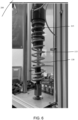
- Figure 6 is a perspective view of a shock assembly 100 with a spring preload system 200, in accordance with an embodiment.
- helical spring 115 and spring 215 can be seen as separate springs.
- the spring preload system is formed in a cylinder separate from shock assembly 100 and is connected via hosing.
- the hosing is fluidly connected to the compression chamber of the shock assembly 100 (whether mono tube, concentric tube, etc.) with the spring preload system.
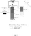
- Figure 7 is a hydraulic overview of a remote spring preload system 700, in accordance with an embodiment. Also included are preload cylinder 206, check shim 724, and check spring 726.
- preload cylinder 706 is located in a position remote from shock assembly 100.
- a rotary motor e.g., DC, stepper, etc.
- check shim 724 is shaped to where it can have the ports in and out of preload cylinder 706 simultaneously covered or open (e.g., rectangularly shaped, clover shaped, etc.).
- check shim 724 is shaped to where at least one port can be covered (e.g., clover shaped, scattered openings, etc.).
- Check spring 726 is used to bias check shim 724 towards a closed position.
- spring preload system 700 has similar mechanics to spring preload system 200. For example, a compression stroke of shock assembly 100 will cause fluid to flow from shock assembly 100 to the base valve and to the preload cylinder 706.
- Check shim 724 when in a closed position, is used to prevent fluid from flowing out of preload cylinder 206 and into external reservoir 125. When check shim 724 is moved to an open position, there is a pressure dump as fluid flows from preload cylinder 206 and to external reservoir 125.
- One advantage of the embodiment shown in at least Figure 7 is an increase in potential preload and compression damping when it is loaded with one valve/check shim 724.
- preload cylinder 206 allows the working fluid to disperse heat and lower any viscosity changes.
- FIG 8 is a perspective view of valve 808, in accordance with an embodiment.
- valve 808 is a FEMA 3 port valve. This would allow for quicker, more expansive control of pumping the preload cylinder, and not being limited by a soft bleed setting.
- Figure 9 is a perspective view of base valve 904, according to an embodiment. Also included in Figure 9 is spring preload adjuster 928, compression adjuster 930, and tube 932.
- Base valve 904 is also designed to be modular, such that a preload system could be installed on a suspension system that did not previously include a preload adjustment system. While the base valve shown in at least Figure 9 is described to be manually adjustable, it should be understood that the system can also be electronically adjustable by utilizing, say, a DC motor, stepper motor, valving, etc.
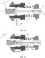
- Figure 10 is a first cross section view of base valve 904, according to an embodiment. Also included are check valve 934, fluid flow arrow 938, chamber 936, and piston 940.
- fluid enters base valve 204 from the compression chamber 212 through check valve 934.
- the spring preload adjuster 928 When the spring preload adjuster 928 is in a closed position (as shown) fluid will follow fluid flow arrow 938 though the valve, and out tube 932. Tube 932 leads to the preload cylinder 206. Fluid can also flow through piston 940 and into chamber 936, which is fluidly connected to external reservoir 125.
- compression adjuster 930 is used to change the position of piston 940. By moving piston 940 to the left (relatively), the preload of the shims on piston 940 is increased. By moving piston 940 to the right, the preload on the shims is lessened. Ports that go through piston 940 can be seen in at least Figure 11 .
- the compression adjuster 930 allows an end user to adjust the settings.
- Figure 11 is a second cross section view of base valve 204, according to an embodiment. Also included are fluid flow arrows 938 and flow path 942.
- spring preload adjuster 928 when the spring preload adjuster 928 is moved to an open position fluid is then able to flow through flow path 942, which connects to chamber 936. It should be understood that while spring preload adjuster 928 is shown in a closed position, an open position would have spring preload adjuster 928 moved slightly to the left of what is shown such that chamber 936 is in fluid communication with second chamber 944.
- Figure 12 is a hydraulic overview of spring preload system 1200, in accordance with an embodiment. Also included is two-way electronic valve 1246.
- a two-way electronic valve 1246 is used to meter fluid flow in and out of preload cylinder 206. It should be understood that any of the previously discussed base valve embodiments are compatible with the embodiment shown in at least Figure 12 .
- the two-way electronic valve 1246 is tied into the fluid flow path connecting to the external reservoir 125.
- the two-way electronic valve 1246 is tied into the fluid flow path of the compression chamber.
- a three-port valve (such as valve 808) is used instead. In embodiments with a three-port valve, the compression damping settings can be altered while in a steady state setting.
Landscapes
- Engineering & Computer Science (AREA)
- Mechanical Engineering (AREA)
- Fluid-Damping Devices (AREA)
Applications Claiming Priority (1)
| Application Number | Priority Date | Filing Date | Title |
|---|---|---|---|
| US202263339342P | 2022-05-06 | 2022-05-06 |
Publications (1)
| Publication Number | Publication Date |
|---|---|
| EP4272983A1 true EP4272983A1 (fr) | 2023-11-08 |
Family
ID=86330769
Family Applications (1)
| Application Number | Title | Priority Date | Filing Date |
|---|---|---|---|
| EP23172168.9A Pending EP4272983A1 (fr) | 2022-05-06 | 2023-05-08 | Système de précharge de ressort |
Country Status (2)
| Country | Link |
|---|---|
| US (1) | US12409697B2 (fr) |
| EP (1) | EP4272983A1 (fr) |
Cited By (1)
| Publication number | Priority date | Publication date | Assignee | Title |
|---|---|---|---|---|
| US20250128559A1 (en) * | 2023-10-23 | 2025-04-24 | Fox Factory, Inc. | Wheelie control suspension system for snowmobiles |
Citations (11)
| Publication number | Priority date | Publication date | Assignee | Title |
|---|---|---|---|---|
| US5556082A (en) * | 1993-12-07 | 1996-09-17 | Showa Corporation | Cushion unit |
| JP3108078B2 (ja) * | 1990-06-19 | 2000-11-13 | 株式会社シヨーワ | 車両用油圧緩衝器の車高調整装置 |
| US6296092B1 (en) | 1998-10-28 | 2001-10-02 | Fox Factory, Inc. | Position-sensitive shock absorber |
| US7374028B2 (en) | 2003-07-08 | 2008-05-20 | Fox Factory, Inc. | Damper with pressure-sensitive compression damping |
| US8838335B2 (en) | 2011-09-12 | 2014-09-16 | Fox Factory, Inc. | Methods and apparatus for suspension set up |
| US9353818B2 (en) | 2009-01-07 | 2016-05-31 | Fox Factory, Inc. | Remotely operated bypass for a suspension damper |
| US9623716B2 (en) | 2012-02-03 | 2017-04-18 | Fox Factory, Inc. | Suspension with hydraulic preload adjust |
| US10036443B2 (en) | 2009-03-19 | 2018-07-31 | Fox Factory, Inc. | Methods and apparatus for suspension adjustment |
| DE102018210447B3 (de) * | 2018-06-27 | 2019-06-06 | Zf Friedrichshafen Ag | Verstellbarer Federträger |
| US10576803B2 (en) | 2014-09-17 | 2020-03-03 | Fox Factory, Inc. | Shock absorber |
| EP4147889A1 (fr) * | 2021-09-08 | 2023-03-15 | Volvo Car Corporation | Système d'amortisseur et procédé de changement de garde au sol d'un véhicule |
Family Cites Families (12)
| Publication number | Priority date | Publication date | Assignee | Title |
|---|---|---|---|---|
| JPH079682Y2 (ja) * | 1988-09-21 | 1995-03-08 | 株式会社シヨーワ | 車両用緩衝器の油圧式車高調整装置 |
| US4921080A (en) * | 1989-05-08 | 1990-05-01 | Lin Chien H | Hydraulic shock absorber |
| DE4231641C2 (de) * | 1992-09-22 | 1996-12-12 | Daimler Benz Ag | Federbein für Federungssysteme von Kraftfahrzeugen |
| US6318525B1 (en) * | 1999-05-07 | 2001-11-20 | Marzocchi, S.P.A. | Shock absorber with improved damping |
| DE10123491A1 (de) * | 2001-05-15 | 2002-11-21 | Porsche Ag | Verstellbares Federbein für ein Kraftfahrzeug |
| US9033122B2 (en) | 2009-01-07 | 2015-05-19 | Fox Factory, Inc. | Method and apparatus for an adjustable damper |
| US9239090B2 (en) | 2009-01-07 | 2016-01-19 | Fox Factory, Inc. | Suspension damper with remotely-operable valve |
| US8627932B2 (en) | 2009-01-07 | 2014-01-14 | Fox Factory, Inc. | Bypass for a suspension damper |
| JP6266870B2 (ja) * | 2012-09-19 | 2018-01-24 | 株式会社ショーワ | 自動二輪車 |
| DE102014207055B4 (de) * | 2014-03-04 | 2016-05-12 | Zf Friedrichshafen Ag | Schwingungsdämpfer mit Niveauregulierung |
| US11718137B2 (en) | 2020-02-27 | 2023-08-08 | Fox Factory, Inc. | Shock assembly with automatically adjustable ride height |
| US11840120B2 (en) | 2020-02-27 | 2023-12-12 | Fox Factory, Inc. | IFP shock with automatically adjustable ride height |
-
2023
- 2023-05-08 US US18/144,792 patent/US12409697B2/en active Active
- 2023-05-08 EP EP23172168.9A patent/EP4272983A1/fr active Pending
Patent Citations (11)
| Publication number | Priority date | Publication date | Assignee | Title |
|---|---|---|---|---|
| JP3108078B2 (ja) * | 1990-06-19 | 2000-11-13 | 株式会社シヨーワ | 車両用油圧緩衝器の車高調整装置 |
| US5556082A (en) * | 1993-12-07 | 1996-09-17 | Showa Corporation | Cushion unit |
| US6296092B1 (en) | 1998-10-28 | 2001-10-02 | Fox Factory, Inc. | Position-sensitive shock absorber |
| US7374028B2 (en) | 2003-07-08 | 2008-05-20 | Fox Factory, Inc. | Damper with pressure-sensitive compression damping |
| US9353818B2 (en) | 2009-01-07 | 2016-05-31 | Fox Factory, Inc. | Remotely operated bypass for a suspension damper |
| US10036443B2 (en) | 2009-03-19 | 2018-07-31 | Fox Factory, Inc. | Methods and apparatus for suspension adjustment |
| US8838335B2 (en) | 2011-09-12 | 2014-09-16 | Fox Factory, Inc. | Methods and apparatus for suspension set up |
| US9623716B2 (en) | 2012-02-03 | 2017-04-18 | Fox Factory, Inc. | Suspension with hydraulic preload adjust |
| US10576803B2 (en) | 2014-09-17 | 2020-03-03 | Fox Factory, Inc. | Shock absorber |
| DE102018210447B3 (de) * | 2018-06-27 | 2019-06-06 | Zf Friedrichshafen Ag | Verstellbarer Federträger |
| EP4147889A1 (fr) * | 2021-09-08 | 2023-03-15 | Volvo Car Corporation | Système d'amortisseur et procédé de changement de garde au sol d'un véhicule |
Cited By (1)
| Publication number | Priority date | Publication date | Assignee | Title |
|---|---|---|---|---|
| US20250128559A1 (en) * | 2023-10-23 | 2025-04-24 | Fox Factory, Inc. | Wheelie control suspension system for snowmobiles |
Also Published As
| Publication number | Publication date |
|---|---|
| US20240116324A1 (en) | 2024-04-11 |
| US12409697B2 (en) | 2025-09-09 |
Similar Documents
| Publication | Publication Date | Title |
|---|---|---|
| US20250050701A1 (en) | Shock absorber with a bearing housing bypass assembly | |
| US12496867B2 (en) | Hydraulically-adjustable preload and/or cross-over | |
| US12325276B2 (en) | IFP shock with automatically adjustable ride height | |
| US12502923B2 (en) | Hydraulic cross-linked suspension | |
| US12227048B2 (en) | Shock assembly with automatically adjustable ride height | |
| US12311720B2 (en) | Hydraulic cross-linked suspension | |
| US20230302867A1 (en) | Hydraulic cross-linked suspension | |
| US12253139B2 (en) | Dual live valve shock having main damper and base valve actively controlled | |
| US8123235B2 (en) | Hydraulic system for a vehicle suspension | |
| EP4253106A1 (fr) | Suspension hydraulique reticulee | |
| US20230356558A1 (en) | Shock assembly with by-pass and hydraulic adjust | |
| US20240286452A1 (en) | Shuttle valve shock assembly | |
| EP4272983A1 (fr) | Système de précharge de ressort | |
| US20250313055A1 (en) | Valve-controlled fluid circuits for rebound damping adjustment | |
| EP4407208A1 (fr) | Ensemble soupape active | |
| US20230330792A1 (en) | Spring compressor | |
| US20250129833A1 (en) | Dual piston shock assembly | |
| US20240410440A1 (en) | Piston fluid flow dynamics, temperature stability, and noise mitigation | |
| TWI917961B (zh) | 流體重新定向和防空化系統以及懸架和防空化系統 | |
| EP4290090A1 (fr) | Matériel de palier intégré pour ensemble de choc | |
| US20250153801A1 (en) | Valve-controlled fluid circuits | |
| EP4040011A1 (fr) | Amortisseur doté d'un système d'écoulement de soupape à base annulaire |
Legal Events
| Date | Code | Title | Description |
|---|---|---|---|
| PUAI | Public reference made under article 153(3) epc to a published international application that has entered the european phase |
Free format text: ORIGINAL CODE: 0009012 |
|
| STAA | Information on the status of an ep patent application or granted ep patent |
Free format text: STATUS: THE APPLICATION HAS BEEN PUBLISHED |
|
| AK | Designated contracting states |
Kind code of ref document: A1 Designated state(s): AL AT BE BG CH CY CZ DE DK EE ES FI FR GB GR HR HU IE IS IT LI LT LU LV MC ME MK MT NL NO PL PT RO RS SE SI SK SM TR |
|
| STAA | Information on the status of an ep patent application or granted ep patent |
Free format text: STATUS: REQUEST FOR EXAMINATION WAS MADE |
|
| 17P | Request for examination filed |
Effective date: 20240327 |
|
| RBV | Designated contracting states (corrected) |
Designated state(s): AL AT BE BG CH CY CZ DE DK EE ES FI FR GB GR HR HU IE IS IT LI LT LU LV MC ME MK MT NL NO PL PT RO RS SE SI SK SM TR |
|
| STAA | Information on the status of an ep patent application or granted ep patent |
Free format text: STATUS: EXAMINATION IS IN PROGRESS |
|
| 17Q | First examination report despatched |
Effective date: 20250708 |