EP4276423B1 - Inspektionsvorrichtung mit darin integrierter röntgen- und wägevorrichtung - Google Patents
Inspektionsvorrichtung mit darin integrierter röntgen- und wägevorrichtung Download PDFInfo
- Publication number
- EP4276423B1 EP4276423B1 EP23171543.4A EP23171543A EP4276423B1 EP 4276423 B1 EP4276423 B1 EP 4276423B1 EP 23171543 A EP23171543 A EP 23171543A EP 4276423 B1 EP4276423 B1 EP 4276423B1
- Authority
- EP
- European Patent Office
- Prior art keywords
- weighing
- region
- inspection
- belt
- area
- Prior art date
- Legal status (The legal status is an assumption and is not a legal conclusion. Google has not performed a legal analysis and makes no representation as to the accuracy of the status listed.)
- Active
Links
Images

Classifications
-
- G—PHYSICS
- G01—MEASURING; TESTING
- G01G—WEIGHING
- G01G19/00—Weighing apparatus or methods adapted for special purposes not provided for in the preceding groups
- G01G19/02—Weighing apparatus or methods adapted for special purposes not provided for in the preceding groups for weighing wheeled or rolling bodies, e.g. vehicles
- G01G19/03—Weighing apparatus or methods adapted for special purposes not provided for in the preceding groups for weighing wheeled or rolling bodies, e.g. vehicles for weighing during motion
- G01G19/035—Weighing apparatus or methods adapted for special purposes not provided for in the preceding groups for weighing wheeled or rolling bodies, e.g. vehicles for weighing during motion using electrical weight-sensitive devices
-
- G—PHYSICS
- G01—MEASURING; TESTING
- G01N—INVESTIGATING OR ANALYSING MATERIALS BY DETERMINING THEIR CHEMICAL OR PHYSICAL PROPERTIES
- G01N23/00—Investigating or analysing materials by the use of wave or particle radiation, e.g. X-rays or neutrons, not covered by groups G01N3/00 – G01N17/00, G01N21/00 or G01N22/00
- G01N23/02—Investigating or analysing materials by the use of wave or particle radiation, e.g. X-rays or neutrons, not covered by groups G01N3/00 – G01N17/00, G01N21/00 or G01N22/00 by transmitting the radiation through the material
- G01N23/06—Investigating or analysing materials by the use of wave or particle radiation, e.g. X-rays or neutrons, not covered by groups G01N3/00 – G01N17/00, G01N21/00 or G01N22/00 by transmitting the radiation through the material and measuring the absorption
- G01N23/083—Investigating or analysing materials by the use of wave or particle radiation, e.g. X-rays or neutrons, not covered by groups G01N3/00 – G01N17/00, G01N21/00 or G01N22/00 by transmitting the radiation through the material and measuring the absorption the radiation being X-rays
-
- B—PERFORMING OPERATIONS; TRANSPORTING
- B07—SEPARATING SOLIDS FROM SOLIDS; SORTING
- B07C—POSTAL SORTING; SORTING INDIVIDUAL ARTICLES, OR BULK MATERIAL FIT TO BE SORTED PIECE-MEAL, e.g. BY PICKING
- B07C5/00—Sorting according to a characteristic or feature of the articles or material being sorted, e.g. by control effected by devices which detect or measure such characteristic or feature; Sorting by manually actuated devices, e.g. switches
- B07C5/02—Measures preceding sorting, e.g. arranging articles in a stream orientating
-
- B—PERFORMING OPERATIONS; TRANSPORTING
- B07—SEPARATING SOLIDS FROM SOLIDS; SORTING
- B07C—POSTAL SORTING; SORTING INDIVIDUAL ARTICLES, OR BULK MATERIAL FIT TO BE SORTED PIECE-MEAL, e.g. BY PICKING
- B07C5/00—Sorting according to a characteristic or feature of the articles or material being sorted, e.g. by control effected by devices which detect or measure such characteristic or feature; Sorting by manually actuated devices, e.g. switches
- B07C5/16—Sorting according to weight
- B07C5/18—Sorting according to weight using a single stationary weighing mechanism
-
- B—PERFORMING OPERATIONS; TRANSPORTING
- B07—SEPARATING SOLIDS FROM SOLIDS; SORTING
- B07C—POSTAL SORTING; SORTING INDIVIDUAL ARTICLES, OR BULK MATERIAL FIT TO BE SORTED PIECE-MEAL, e.g. BY PICKING
- B07C5/00—Sorting according to a characteristic or feature of the articles or material being sorted, e.g. by control effected by devices which detect or measure such characteristic or feature; Sorting by manually actuated devices, e.g. switches
- B07C5/16—Sorting according to weight
- B07C5/28—Sorting according to weight using electrical control means
-
- B—PERFORMING OPERATIONS; TRANSPORTING
- B07—SEPARATING SOLIDS FROM SOLIDS; SORTING
- B07C—POSTAL SORTING; SORTING INDIVIDUAL ARTICLES, OR BULK MATERIAL FIT TO BE SORTED PIECE-MEAL, e.g. BY PICKING
- B07C5/00—Sorting according to a characteristic or feature of the articles or material being sorted, e.g. by control effected by devices which detect or measure such characteristic or feature; Sorting by manually actuated devices, e.g. switches
- B07C5/34—Sorting according to other particular properties
- B07C5/3416—Sorting according to other particular properties according to radiation transmissivity, e.g. for light, x-rays, particle radiation
-
- B—PERFORMING OPERATIONS; TRANSPORTING
- B07—SEPARATING SOLIDS FROM SOLIDS; SORTING
- B07C—POSTAL SORTING; SORTING INDIVIDUAL ARTICLES, OR BULK MATERIAL FIT TO BE SORTED PIECE-MEAL, e.g. BY PICKING
- B07C5/00—Sorting according to a characteristic or feature of the articles or material being sorted, e.g. by control effected by devices which detect or measure such characteristic or feature; Sorting by manually actuated devices, e.g. switches
- B07C5/36—Sorting apparatus characterised by the means used for distribution
- B07C5/361—Processing or control devices therefor, e.g. escort memory
-
- B—PERFORMING OPERATIONS; TRANSPORTING
- B07—SEPARATING SOLIDS FROM SOLIDS; SORTING
- B07C—POSTAL SORTING; SORTING INDIVIDUAL ARTICLES, OR BULK MATERIAL FIT TO BE SORTED PIECE-MEAL, e.g. BY PICKING
- B07C5/00—Sorting according to a characteristic or feature of the articles or material being sorted, e.g. by control effected by devices which detect or measure such characteristic or feature; Sorting by manually actuated devices, e.g. switches
- B07C5/36—Sorting apparatus characterised by the means used for distribution
- B07C5/361—Processing or control devices therefor, e.g. escort memory
- B07C5/362—Separating or distributor mechanisms
-
- G—PHYSICS
- G01—MEASURING; TESTING
- G01G—WEIGHING
- G01G11/00—Apparatus for weighing a continuous stream of material during flow; Conveyor belt weighers
- G01G11/003—Details; specially adapted accessories
-
- G—PHYSICS
- G01—MEASURING; TESTING
- G01G—WEIGHING
- G01G19/00—Weighing apparatus or methods adapted for special purposes not provided for in the preceding groups
- G01G19/52—Weighing apparatus combined with other objects, e.g. furniture
-
- G—PHYSICS
- G01—MEASURING; TESTING
- G01N—INVESTIGATING OR ANALYSING MATERIALS BY DETERMINING THEIR CHEMICAL OR PHYSICAL PROPERTIES
- G01N23/00—Investigating or analysing materials by the use of wave or particle radiation, e.g. X-rays or neutrons, not covered by groups G01N3/00 – G01N17/00, G01N21/00 or G01N22/00
- G01N23/02—Investigating or analysing materials by the use of wave or particle radiation, e.g. X-rays or neutrons, not covered by groups G01N3/00 – G01N17/00, G01N21/00 or G01N22/00 by transmitting the radiation through the material
- G01N23/04—Investigating or analysing materials by the use of wave or particle radiation, e.g. X-rays or neutrons, not covered by groups G01N3/00 – G01N17/00, G01N21/00 or G01N22/00 by transmitting the radiation through the material and forming images of the material
-
- G—PHYSICS
- G01—MEASURING; TESTING
- G01N—INVESTIGATING OR ANALYSING MATERIALS BY DETERMINING THEIR CHEMICAL OR PHYSICAL PROPERTIES
- G01N2223/00—Investigating materials by wave or particle radiation
- G01N2223/60—Specific applications or type of materials
- G01N2223/643—Specific applications or type of materials object on conveyor
Definitions
- the invention relates to an inspection device which contains a device for inspection by means of electromagnetic radiation, in particular an X-ray device, and a weighing device in a preferably curtainless radiation protection housing.
- Such inspection devices are used, for example, in the food industry as well as in the pharmaceutical industry, where unpackaged products are also checked for their flawless quality and weight.
- the present invention is therefore based on the object of creating an inspection device which avoids the aforementioned problems and enables both inspection by means of electromagnetic radiation, in particular X-ray inspection, and weighing of products (packaged, unpackaged or in still open containers) whereby the inspection results are highly accurate and incorrect results are avoided. Furthermore, a short design in the conveying direction is desired.
- the inspection device includes both a device for inspection by means of electromagnetic radiation, in particular an X-ray device, and a weighing device, a short design in the x-direction (conveying direction) is advantageously possible.
- a device for inspection by means of electromagnetic radiation in the conveying direction
- an X-ray device in front of a weighing device serves as a calming section for the run of the belt and, if applicable, the product, so that the belt runs more smoothly in the area of the weighing device, reducing the risk of belt flutter and enabling a shorter design (or shorter length) of the entire device.
- the inspection device has an inclined area on the output side and a weighing device which is arranged directly in front of the inclined area when viewed in the x-direction.
- the inclined area is preferably designed as a plate, in particular as a folded sheet metal. It is of course also conceivable to form the inclined area using at least one deflection roller.
- the belt is pulled downwards over the inclined region (taking into account the belt elasticity) and is guided on this, the belt in the area immediately in front of the inclined region - and thus the area of the weighing device - has a uniform belt path without movement (lifting) in the z-direction (height direction).
- the (albeit slightly) higher belt tension compared to upstream belt areas can prevent undesirable belt fluttering or bulging (before the deflection point or change in direction of the belt).
- This partial pulling, at least in the area of the weighing device can be increased by the geometry of the belt guide, by appropriately arranging a drive roller, in particular a tractor roller, closer to the area of the weighing device and/or by appropriate rollers and/or upstream belt guides with a braking effect (inhibition) in the product flow (before the weighing device).
- the belt section from the weighing device to the drive roller 21 (output side) is shorter than the belt section from the drive roller to the weighing device (belt geometry).
- the belt travels as explained above in such a way that the belt is pulled not only in the area of the weighing device, but preferably also in the area of the device for inspection using electromagnetic radiation (in the conveying direction), in particular the X-ray device, it is also advantageously possible to avoid bulging, stretching, etc. in the belt travel direction in the X-ray device.
- Such effects could otherwise have an undesirable effect on the synchronicity and quality of the images recorded, in particular lines per time and unit of length, during inspection using electromagnetic radiation, in particular during X-rays.
- the belt is preferably driven at a defined speed profile, in particular a constant speed, in order to enable the operation of the device for inspection by means of electromagnetic radiation (in the conveying direction), in particular an X-ray device with a cost-effective line camera which requires a defined line value per unit of time.
- the inclined region is preferably arranged in the inspection device in such a way that its weight is not taken into account when weighing a previously X-rayed product. Accordingly, when the weighing device is arranged in the immediate vicinity of the inclined region, there is no (force-locking) connection between a load-bearing part of the weighing device and the inclined region, so that the dead weight of the inclined region is not taken into account when weighing.
- the device for inspection by means of electromagnetic radiation in the conveying direction
- the weighing device and at least a partial area of the inclined area are encircled by a common endless conveyor belt.
- the slanted area prevents X-rays (or other dangerous radiation such as terahertz radiation) from escaping from the radiation protection housing, even without an additional radiation protection curtain. This eliminates the need for radiation protection curtains and the associated problems such as soiling and wear. Accordingly, cleaning and abrasion monitoring of the radiation protection curtains, especially lead curtains, can also be dispensed with.
- the X-ray device (with X-ray source) is not in the immediate vicinity of the exit area due to its upstream position (in the conveying direction) in front of the weighing device.
- the upper run of the endless belt overcomes a height difference opposite to the z-direction by means of an inclined area on its way from the weighing area to the exit area. In this way, the level of the exit area can be adapted to different conditions.
- the weighing device is designed as a module so that it can be inserted into the inspection device and removed from it.
- At least one partial area is arranged as a section of the inclined area as an integral component in a fixed position on the modular weighing device.
- this part is designed as a plate, in particular as a folded sheet metal. It is of course also conceivable to form this part of the inclined area, for example, using one, two or more deflection rollers.
- the modular, integrated design makes it possible to produce the section for the weighing device already adjusted at the factory, so that any adjustment that would otherwise be required when inserting the module can be omitted.
- the modular design facilitates maintenance, cleaning, repairs, etc. of the device, as these can be carried out without dismantling a fully assembled system, apart from relaxing or removing the belt.
- the section of the inclined area is arranged on the weighing device in such a way that its weight is not taken into account when weighing a previously X-rayed product.
- the inclined Area must be arranged on the (stationary) land-side area of the weighing device or the load cell itself, so that a load-bearing area of the weighing device remains unaffected.
- the drive for the belt can also be mounted on land, so that the drive does not have to be taken into account as a preload when weighing.
- At least a portion of the inclined region is designed as a component of an ejector or a sorter.
- an ejector or sorter can be designed as a separate belt conveyor or as a simple chute.
- an ejector or sorter in the form of a folding mechanism acting in the z-direction (in particular, folding up and/or down a partial area with a pivot axis in the y-direction).
- Such an ejector or sorter can also be part of the radiation protection.
- the ejector or sorter in a certain swivel position of the sub-area can also help prevent the ingress of extraneous light.
- the weighing device comprises at least one weighing cell and at least one weighing platform, which is preferably designed as a bent sheet metal part. It is also conceivable that several weighing cells are provided for each platform. Several weighing platforms can be provided adjacent to each other in the x-direction as well as adjacent to each other in the y-direction (band width). In this way, precise weighing of products of different sizes on several platforms as well as multi-track weighing can be made possible.
- a belt alignment unit is arranged in a fixed position on the modular weighing device as an integral component upstream (of the product) of the weighing platform and in alignment with the latter.
- the upper run of the endless belt overcomes a height difference in the z-direction on its way from the entry area to the area for inspection by means of electromagnetic radiation, in particular for X-rays, whereby the upper run in this area is preferably designed as an entry ramp.
- the level of the entry area and the level of the exit area can be adapted to different conditions.
- the input area and output area of the inspection device are essentially at the same height with respect to the z-direction, so that the inspection device can be used in existing production lines operating at the same level without changing the level.
- a device for inspection by means of electromagnetic radiation in particular an X-ray device, i.e. a radiation source, in particular an X-ray source and a radiation detector, in particular an X-ray detector, preferably a line camera, and a weighing device, i.e. a load cell with a load receiver, in particular a weighing platform, is located within a radiation protection housing and thus integrated into the inspection device.
- an X-ray device i.e. a radiation source, in particular an X-ray source and a radiation detector, in particular an X-ray detector, preferably a line camera
- a weighing device i.e. a load cell with a load receiver, in particular a weighing platform
- a device for inspection using electromagnetic radiation allows the radiation to penetrate products or be reflected by the product.
- the power supply and the signal transmission of the device for inspection using electromagnetic radiation, in particular the X-ray device, and the weighing device are carried out in a known manner.
- corresponding evaluation units for X-raying and weighing the products can be located outside the radiation protection housing, whereby the signal transmission to these evaluation units can take place via cable (electrical, optical) or wirelessly.
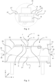
- the inspection device 1 shown represents a schematic side view with the front wall of a radiation protection housing 3 removed for reasons of easier comprehensibility.
- the radiation protection housing 3 is a closed one with the exception of openings for an entrance area 39 and an exit area 41.
- the openings in the radiation protection housing 3 for the entrance area 39 and the exit area 41 are preferably kept as small as possible depending on the product height and width, so that optimal radiation protection is possible while simultaneously conveying the products 33.
- Products 33 are conveyed into the inspection device 1 via the entrance area 39 in a manner not shown in detail and leave the inspection device 1 again via the exit area 41.
- Entrance area 39 and exit area 41 are located, as in Fig. 1 and Fig. 3 shown, at the same height in the z-direction.
- a product 33 is conveyed to a horizontal level via an entrance ramp 29 leading diagonally upwards by means of a circulating endless belt 19.
- the belt and the products located thereon are supported in its width (extending in the y-direction) up to and after an X-ray device by means of belt guide elements 35, 37 extending in the y-direction and in the x-direction.
- the X-ray device 5 comprises an X-ray source 7 above the upper run of the belt 19 and an X-ray detector 9 below the upper run, vertically below the X-ray source 7, so that products 33 located on the belt 19 are X-rayed.
- the X-ray radiation penetrates the product 33 at this point and the belt 19 passes through a gap between the belt guide elements 35 and 37 and hits the X-ray detector 9, which is preferably designed as a line camera.
- the product 33 On its way from the input area 39 to the output area 41, the product 33 travels along a trapezoidal path. After passing through the X-ray device, the product 33 is conveyed, supported by the guide element 37, to a weighing device 11, which is preferably designed as a load cell 15 with a load-bearing weighing platform 13.
- the weighing platform 13 for example a bent sheet metal part, rests on the underside of the belt so that the weight or weight force of the product 33 at this area of the upper run of the belt 19 is detected by the weighing device 11.
- the load cell 15 is, as shown Fig. 1 and Fig. 3 visible, and also located on the mainland.
- the power supply and the signal transmission from the X-ray device 5 and the weighing device 11 are carried out in a known manner and not shown in the drawing.
- corresponding evaluation units for X-raying and weighing the products 33 can be located outside the radiation protection housing 3, whereby the signal transmission to these evaluation units can take place via cable (electrical, optical) or wirelessly.
- the product 33 is conveyed over an inclined area 17 from the raised horizontal side of the trapezoid back down to the exit area 41 and leaves the inspection device 1 via the exit area 41.
- Fig. 1 and Fig. 3 shown schematically as an example for a production line with corresponding ends of the belt conveyors of the production line connected to the input area 39 and output area 41.
- the inspection device it is also conceivable to operate the inspection device as a stand-alone device, with the input area 39 and output area 41 being served in a different way and products 33 being delivered and removed.
- the drive roller 21 can be arranged centrally or at another location with respect to the entire belt path, as shown.
- the belt section from the weighing device 11 to the drive roller 21 (output side) is shorter than the belt section from the drive roller 21 to the weighing device 11 (belt geometry).
- the belt 19 pulled downwards over the inclined area lies at the deflection point 25 (see Fig. 2 ) so that lifting of the belt 19 or even belt fluttering as well as bulging is avoided.
- the weighing device in particular its weighing platform 13, is, as can be seen from Fig. 1 , Fig. 2 as well as Fig. 3 As can be seen, it is arranged in the direction of belt travel in the immediate vicinity of the inclined region 17 and thus its deflection point 25, so that the load receptors of the weighing device, in particular the weighing platform 13 and deflection point 25, are aligned with one another.
- the run of the belt 19 is designed in such a way that the belt is pulled not only in the area of the weighing device 11, but preferably also in the area of the X-ray device 5, it is also advantageously possible to avoid bulging, stretching, etc. in the belt running direction in the X-ray device, which could impair the synchronicity of the recorded images, in particular lines per time and Unit of length, can have an undesirable effect on X-rays. In this way, negative influences on image quality can be prevented.
- a part of the inclined area 17 is designed as a section 23, preferably as a bent sheet metal, as seen in the direction of belt travel.
- the section 23 therefore contains the deflection point 25, which can of course also be rounded instead of angular.
- the section 23 preferably has a horizontal area which, like the deflection point 25, is aligned with the weighing platform 13.
- Section 23 is located directly on a mainland area (in Fig. 2 on the underside) of the load cell 15 and preferably integrated in the weighing device 11, which is designed as a module that can be used and exchanged.
- the exact adjustment of the section 23 so that the deflection point 25 (or the peripheral edge extending in the y-direction) and the possibly adjoining horizontal area are aligned with the weighing platform 13 can be carried out at the factory during manufacture, without such fine adjustment having to be carried out when inserting the module into the inspection device (manufacturing, maintenance, cleaning, exchange, etc.).
- a belt alignment unit 27 may be provided which has a horizontal area 27' which is also aligned with the weighing platform 13. In front of this horizontal area 27' there may be an inclined area which serves as a ramp leading the belt 19 upwards.
- the belt alignment unit 27 can also, like section 23, be mounted directly on a land-side area (in Fig. 2 on the underside) of the load cell 15 and preferably integrated in the weighing device 11, which is designed as a module and can be used and exchanged.
- the exact adjustment of the belt alignment unit 27 so that its horizontal area 27 ⁇ is aligned with the weighing platform 13 can be carried out at the factory during manufacture, without such fine adjustment having to be carried out when inserting the module into the inspection device (manufacturing, maintenance, cleaning, exchange, etc.).
- the second embodiment has an ejector 31 (or sorter).
- the inclined area 17 ends in this case with section 23.
- Its continuation in the direction of the exit region 41 is partially designed as a pivotable region, for example in the form of a plate, which has a pivot axis lying in the region of the exit 41 perpendicular to the plane of the drawing (y-axis).
- area 31 can be used as in Fig. 3 shown, can be pivoted upwards so that a product (33 ⁇ ) found to be defective falls into a collecting container 43 located underneath.
- products 33 that pass the inspection are conveyed to the exit area via the area 31 in the closed or non-upwardly pivoted position, in which the area 31 is flush with the section 23 (where there may be a joint gap or a gap therebetween).
- the area 31 can be designed as a separate belt conveyor or as a simple slide. In this Fig. 3 In the case shown, the area 31 is not surrounded by the belt 19, so that the run of the belt 19 is not influenced by the ejector 31.
Landscapes
- Health & Medical Sciences (AREA)
- Physics & Mathematics (AREA)
- General Physics & Mathematics (AREA)
- General Health & Medical Sciences (AREA)
- Life Sciences & Earth Sciences (AREA)
- Chemical & Material Sciences (AREA)
- Analytical Chemistry (AREA)
- Biochemistry (AREA)
- Immunology (AREA)
- Pathology (AREA)
- Toxicology (AREA)
- Analysing Materials By The Use Of Radiation (AREA)
Applications Claiming Priority (1)
| Application Number | Priority Date | Filing Date | Title |
|---|---|---|---|
| DE102022111511.9A DE102022111511A1 (de) | 2022-05-09 | 2022-05-09 | Inspektionsvorrichtung mit darin integrierter Röntgen- und Wägevorrichtung |
Publications (3)
| Publication Number | Publication Date |
|---|---|
| EP4276423A1 EP4276423A1 (de) | 2023-11-15 |
| EP4276423B1 true EP4276423B1 (de) | 2024-10-09 |
| EP4276423C0 EP4276423C0 (de) | 2024-10-09 |
Family
ID=86329171
Family Applications (1)
| Application Number | Title | Priority Date | Filing Date |
|---|---|---|---|
| EP23171543.4A Active EP4276423B1 (de) | 2022-05-09 | 2023-05-04 | Inspektionsvorrichtung mit darin integrierter röntgen- und wägevorrichtung |
Country Status (7)
| Country | Link |
|---|---|
| US (1) | US12209976B2 (pl) |
| EP (1) | EP4276423B1 (pl) |
| JP (1) | JP7536141B2 (pl) |
| CN (1) | CN116511084A (pl) |
| DE (1) | DE102022111511A1 (pl) |
| ES (1) | ES3000101T3 (pl) |
| PL (1) | PL4276423T3 (pl) |
Families Citing this family (3)
| Publication number | Priority date | Publication date | Assignee | Title |
|---|---|---|---|---|
| CN115683289B (zh) * | 2021-07-29 | 2024-12-03 | 梅特勒-托利多(常州)精密仪器有限公司 | 集成式高精度称重模块 |
| EP4556898A1 (en) * | 2023-11-15 | 2025-05-21 | Malvern Panalytical B.V. | Thin film x-ray analysis apparatus |
| EP4556899A1 (en) * | 2023-11-15 | 2025-05-21 | Malvern Panalytical B.V. | Thin film x-ray analysis apparatus |
Family Cites Families (15)
| Publication number | Priority date | Publication date | Assignee | Title |
|---|---|---|---|---|
| JPH0949883A (ja) | 1995-08-07 | 1997-02-18 | Toshiba Corp | 異物検査装置 |
| CN1188232A (zh) * | 1996-05-09 | 1998-07-22 | 通用信号公司 | 检验计重给料机和带秤校准状态的系统 |
| EP1923147A1 (en) * | 2006-11-14 | 2008-05-21 | Food Machinery Espanola S.A. | Gauge for sorting fruit with a divergent bi-cone feeder |
| CN101271075A (zh) * | 2007-03-22 | 2008-09-24 | 清华大学 | 一种ct扫描安全检查方法及其装置 |
| DE102007032270A1 (de) * | 2007-07-11 | 2009-01-15 | Mettler-Toledo Garvens Gmbh | Vorrichtung zum Prüfen von Produkten und Prüfverfahren |
| JP2010071669A (ja) * | 2008-09-16 | 2010-04-02 | Ishida Co Ltd | 計量装置 |
| JP5615524B2 (ja) * | 2009-10-01 | 2014-10-29 | 大和製衡株式会社 | 重量検査装置 |
| JP5525300B2 (ja) * | 2010-03-24 | 2014-06-18 | アンリツ産機システム株式会社 | X線異物検出装置 |
| FR2981450B1 (fr) | 2011-10-17 | 2014-06-06 | Eads Europ Aeronautic Defence | Systeme et procede de controle de la qualite d'un objet |
| US9599503B2 (en) * | 2015-05-28 | 2017-03-21 | Mettler-Toledo, LLC | Checkweighing device, system, and method of operation |
| CN108369130B (zh) * | 2015-07-13 | 2021-04-30 | 莱特莱姆有限公司 | 一种分流式检重器 |
| CN211168510U (zh) * | 2019-07-31 | 2020-08-04 | 浙江工业大学 | 基于松软输送带结构的高精度流量称 |
| CN110631677B (zh) * | 2019-09-30 | 2025-01-24 | 山东西泰克仪器有限公司 | 滑板检重秤 |
| CN210346882U (zh) * | 2019-09-30 | 2020-04-17 | 山东西泰克仪器有限公司 | 滑板检重秤 |
| CN214151090U (zh) * | 2020-06-10 | 2021-09-07 | 深圳市金检时代科技有限公司 | 一种节能型安检机 |
-
2022
- 2022-05-09 DE DE102022111511.9A patent/DE102022111511A1/de not_active Ceased
-
2023
- 2023-05-02 JP JP2023076152A patent/JP7536141B2/ja active Active
- 2023-05-04 EP EP23171543.4A patent/EP4276423B1/de active Active
- 2023-05-04 ES ES23171543T patent/ES3000101T3/es active Active
- 2023-05-04 PL PL23171543.4T patent/PL4276423T3/pl unknown
- 2023-05-08 US US18/144,784 patent/US12209976B2/en active Active
- 2023-05-09 CN CN202310522614.5A patent/CN116511084A/zh active Pending
Also Published As
| Publication number | Publication date |
|---|---|
| US20240027370A1 (en) | 2024-01-25 |
| CN116511084A (zh) | 2023-08-01 |
| DE102022111511A1 (de) | 2023-11-09 |
| EP4276423A1 (de) | 2023-11-15 |
| JP2023166341A (ja) | 2023-11-21 |
| EP4276423C0 (de) | 2024-10-09 |
| BR102023008873A2 (pt) | 2023-11-14 |
| PL4276423T3 (pl) | 2025-04-22 |
| US12209976B2 (en) | 2025-01-28 |
| JP7536141B2 (ja) | 2024-08-19 |
| ES3000101T3 (en) | 2025-02-27 |
Similar Documents
| Publication | Publication Date | Title |
|---|---|---|
| EP4276423A1 (de) | Inspektionsvorrichtung mit darin integrierter röntgen- und wägevorrichtung | |
| EP3578917B1 (de) | Vorrichtung und verfahren zum scannen von lebensmittelriegeln mit verfahrbarer scaneinheit | |
| EP2748005B1 (de) | Maschine und verfahren zum bedrucken von materialbahnen | |
| DE29518639U1 (de) | Vorrichtung zum Transportieren von Behältern vorbei an einer Einrichtung zum Inspizieren des Bodens der Behälter | |
| EP1187781B1 (de) | Einrichtung zur überwachung einer förderanlage | |
| EP2385356B1 (de) | Wäge- und Sortiervorrichtung | |
| EP2472485A1 (de) | Vorrichtung zum Erfassen von Waren | |
| EP3347706B1 (de) | Vorrichtung zur zerstörungsfreien materialprüfung von gegenständen, insbesondere von felgen und rädern aus leichtmetallguss | |
| WO2021151433A1 (de) | Modularer bandförderer | |
| DE4308725C2 (de) | Münzprüf- und Münzsortiereinrichtung mit Vertikalförderung flachliegender Münzen | |
| DE68921626T2 (de) | Vorrichtung zur Ermittlung von Fremdteilen in Rohbaumwolle. | |
| DE69708534T2 (de) | Gerät zur Untersuchung von Blättern für eine Offsetbogendruckmaschine | |
| EP0572861A1 (de) | Vorrichtung zum Vereinzeln und Fördern elastischer Ringe | |
| DE2143083A1 (de) | Vorrichtung zum Feststellen und Korn gieren von Unebenheiten von bandartigen Erzeugnissen | |
| AT405220B (de) | Rückgabeautomat für verpackungen | |
| EP0290877A2 (de) | Vorrichtung zur maschinellen Rücknahme von Leergut | |
| EP3452948B1 (de) | Scannereinheit | |
| EP3822198B1 (de) | Stückguterfassungsanordnung | |
| DE4300729A1 (pl) | ||
| DE19757527C1 (de) | Optische Breitenmeßvorrichtung für Bandmaterial | |
| DE102015215787A1 (de) | Einrichtung zum Leiten eines Materialstroms | |
| DE2717955A1 (de) | Verfahren und vorrichtung zum ueberwachen der funktionsbereitschaft einer vorrichtung zum ermitteln von fremdkoerpern, verschmutzungen usw. in getraenkeflaschen | |
| AT500001B1 (de) | Münzscheideeinrichtung | |
| DE3731051A1 (de) | Verfahren und vorrichtung zum sortieren von wuerstchen | |
| DE19819633A1 (de) | Teigbearbeitungsmaschine |
Legal Events
| Date | Code | Title | Description |
|---|---|---|---|
| PUAI | Public reference made under article 153(3) epc to a published international application that has entered the european phase |
Free format text: ORIGINAL CODE: 0009012 |
|
| STAA | Information on the status of an ep patent application or granted ep patent |
Free format text: STATUS: THE APPLICATION HAS BEEN PUBLISHED |
|
| AK | Designated contracting states |
Kind code of ref document: A1 Designated state(s): AL AT BE BG CH CY CZ DE DK EE ES FI FR GB GR HR HU IE IS IT LI LT LU LV MC ME MK MT NL NO PL PT RO RS SE SI SK SM TR |
|
| STAA | Information on the status of an ep patent application or granted ep patent |
Free format text: STATUS: REQUEST FOR EXAMINATION WAS MADE |
|
| 17P | Request for examination filed |
Effective date: 20240301 |
|
| RBV | Designated contracting states (corrected) |
Designated state(s): AL AT BE BG CH CY CZ DE DK EE ES FI FR GB GR HR HU IE IS IT LI LT LU LV MC ME MK MT NL NO PL PT RO RS SE SI SK SM TR |
|
| GRAP | Despatch of communication of intention to grant a patent |
Free format text: ORIGINAL CODE: EPIDOSNIGR1 |
|
| STAA | Information on the status of an ep patent application or granted ep patent |
Free format text: STATUS: GRANT OF PATENT IS INTENDED |
|
| RIC1 | Information provided on ipc code assigned before grant |
Ipc: G01N 23/04 20180101ALI20240320BHEP Ipc: G01G 19/52 20060101ALI20240320BHEP Ipc: G01G 19/03 20060101AFI20240320BHEP |
|
| INTG | Intention to grant announced |
Effective date: 20240416 |
|
| GRAS | Grant fee paid |
Free format text: ORIGINAL CODE: EPIDOSNIGR3 |
|
| GRAA | (expected) grant |
Free format text: ORIGINAL CODE: 0009210 |
|
| STAA | Information on the status of an ep patent application or granted ep patent |
Free format text: STATUS: THE PATENT HAS BEEN GRANTED |
|
| AK | Designated contracting states |
Kind code of ref document: B1 Designated state(s): AL AT BE BG CH CY CZ DE DK EE ES FI FR GB GR HR HU IE IS IT LI LT LU LV MC ME MK MT NL NO PL PT RO RS SE SI SK SM TR |
|
| REG | Reference to a national code |
Ref country code: CH Ref legal event code: EP |
|
| REG | Reference to a national code |
Ref country code: DE Ref legal event code: R096 Ref document number: 502023000200 Country of ref document: DE |
|
| REG | Reference to a national code |
Ref country code: IE Ref legal event code: FG4D Free format text: LANGUAGE OF EP DOCUMENT: GERMAN |
|
| U01 | Request for unitary effect filed |
Effective date: 20241106 |
|
| U07 | Unitary effect registered |
Designated state(s): AT BE BG DE DK EE FI FR IT LT LU LV MT NL PT RO SE SI Effective date: 20241115 |
|
| REG | Reference to a national code |
Ref country code: ES Ref legal event code: FG2A Ref document number: 3000101 Country of ref document: ES Kind code of ref document: T3 Effective date: 20250227 |
|
| PG25 | Lapsed in a contracting state [announced via postgrant information from national office to epo] |
Ref country code: IS Free format text: LAPSE BECAUSE OF FAILURE TO SUBMIT A TRANSLATION OF THE DESCRIPTION OR TO PAY THE FEE WITHIN THE PRESCRIBED TIME-LIMIT Effective date: 20250209 Ref country code: HR Free format text: LAPSE BECAUSE OF FAILURE TO SUBMIT A TRANSLATION OF THE DESCRIPTION OR TO PAY THE FEE WITHIN THE PRESCRIBED TIME-LIMIT Effective date: 20241009 |
|
| PG25 | Lapsed in a contracting state [announced via postgrant information from national office to epo] |
Ref country code: NO Free format text: LAPSE BECAUSE OF FAILURE TO SUBMIT A TRANSLATION OF THE DESCRIPTION OR TO PAY THE FEE WITHIN THE PRESCRIBED TIME-LIMIT Effective date: 20250109 |
|
| PG25 | Lapsed in a contracting state [announced via postgrant information from national office to epo] |
Ref country code: GR Free format text: LAPSE BECAUSE OF FAILURE TO SUBMIT A TRANSLATION OF THE DESCRIPTION OR TO PAY THE FEE WITHIN THE PRESCRIBED TIME-LIMIT Effective date: 20250110 |
|
| PG25 | Lapsed in a contracting state [announced via postgrant information from national office to epo] |
Ref country code: RS Free format text: LAPSE BECAUSE OF FAILURE TO SUBMIT A TRANSLATION OF THE DESCRIPTION OR TO PAY THE FEE WITHIN THE PRESCRIBED TIME-LIMIT Effective date: 20250109 |
|
| U20 | Renewal fee for the european patent with unitary effect paid |
Year of fee payment: 3 Effective date: 20250420 |
|
| PG25 | Lapsed in a contracting state [announced via postgrant information from national office to epo] |
Ref country code: SM Free format text: LAPSE BECAUSE OF FAILURE TO SUBMIT A TRANSLATION OF THE DESCRIPTION OR TO PAY THE FEE WITHIN THE PRESCRIBED TIME-LIMIT Effective date: 20241009 |
|
| PGFP | Annual fee paid to national office [announced via postgrant information from national office to epo] |
Ref country code: PL Payment date: 20250417 Year of fee payment: 3 |
|
| PGFP | Annual fee paid to national office [announced via postgrant information from national office to epo] |
Ref country code: ES Payment date: 20250616 Year of fee payment: 3 |
|
| PG25 | Lapsed in a contracting state [announced via postgrant information from national office to epo] |
Ref country code: SK Free format text: LAPSE BECAUSE OF FAILURE TO SUBMIT A TRANSLATION OF THE DESCRIPTION OR TO PAY THE FEE WITHIN THE PRESCRIBED TIME-LIMIT Effective date: 20241009 |
|
| PG25 | Lapsed in a contracting state [announced via postgrant information from national office to epo] |
Ref country code: CZ Free format text: LAPSE BECAUSE OF FAILURE TO SUBMIT A TRANSLATION OF THE DESCRIPTION OR TO PAY THE FEE WITHIN THE PRESCRIBED TIME-LIMIT Effective date: 20241009 |
|
| PLBE | No opposition filed within time limit |
Free format text: ORIGINAL CODE: 0009261 |
|
| STAA | Information on the status of an ep patent application or granted ep patent |
Free format text: STATUS: NO OPPOSITION FILED WITHIN TIME LIMIT |
|
| 26N | No opposition filed |
Effective date: 20250710 |
|
| PG25 | Lapsed in a contracting state [announced via postgrant information from national office to epo] |
Ref country code: MC Free format text: LAPSE BECAUSE OF FAILURE TO SUBMIT A TRANSLATION OF THE DESCRIPTION OR TO PAY THE FEE WITHIN THE PRESCRIBED TIME-LIMIT Effective date: 20241009 |
|
| PG25 | Lapsed in a contracting state [announced via postgrant information from national office to epo] |
Ref country code: IE Free format text: LAPSE BECAUSE OF NON-PAYMENT OF DUE FEES Effective date: 20250504 |
|
| U20 | Renewal fee for the european patent with unitary effect paid |
Year of fee payment: 4 Effective date: 20260331 |