EP4277676B1 - Dérivations avec indicateurs de flux sanguin - Google Patents
Dérivations avec indicateurs de flux sanguin Download PDFInfo
- Publication number
- EP4277676B1 EP4277676B1 EP22739245.3A EP22739245A EP4277676B1 EP 4277676 B1 EP4277676 B1 EP 4277676B1 EP 22739245 A EP22739245 A EP 22739245A EP 4277676 B1 EP4277676 B1 EP 4277676B1
- Authority
- EP
- European Patent Office
- Prior art keywords
- row
- chamber
- appendage
- tube
- blood
- Prior art date
- Legal status (The legal status is an assumption and is not a legal conclusion. Google has not performed a legal analysis and makes no representation as to the accuracy of the status listed.)
- Active
Links
Images


Classifications
-
- A—HUMAN NECESSITIES
- A61—MEDICAL OR VETERINARY SCIENCE; HYGIENE
- A61F—FILTERS IMPLANTABLE INTO BLOOD VESSELS; PROSTHESES; DEVICES PROVIDING PATENCY TO, OR PREVENTING COLLAPSING OF, TUBULAR STRUCTURES OF THE BODY, e.g. STENTS; ORTHOPAEDIC, NURSING OR CONTRACEPTIVE DEVICES; FOMENTATION; TREATMENT OR PROTECTION OF EYES OR EARS; BANDAGES, DRESSINGS OR ABSORBENT PADS; FIRST-AID KITS
- A61F2/00—Filters implantable into blood vessels; Prostheses, i.e. artificial substitutes or replacements for parts of the body; Appliances for connecting them with the body; Devices providing patency to, or preventing collapsing of, tubular structures of the body, e.g. stents
- A61F2/02—Prostheses implantable into the body
- A61F2/04—Hollow or tubular parts of organs, e.g. bladders, tracheae, bronchi or bile ducts
- A61F2/06—Blood vessels
-
- A—HUMAN NECESSITIES
- A61—MEDICAL OR VETERINARY SCIENCE; HYGIENE
- A61M—DEVICES FOR INTRODUCING MEDIA INTO, OR ONTO, THE BODY; DEVICES FOR TRANSDUCING BODY MEDIA OR FOR TAKING MEDIA FROM THE BODY; DEVICES FOR PRODUCING OR ENDING SLEEP OR STUPOR
- A61M1/00—Suction or pumping devices for medical purposes; Devices for carrying-off, for treatment of, or for carrying-over, body-liquids; Drainage systems
- A61M1/36—Other treatment of blood in a by-pass of the natural circulatory system, e.g. temperature adaptation, irradiation ; Extra-corporeal blood circuits
- A61M1/3621—Extra-corporeal blood circuits
- A61M1/3653—Interfaces between patient blood circulation and extra-corporal blood circuit
- A61M1/3655—Arterio-venous shunts or fistulae
-
- A—HUMAN NECESSITIES
- A61—MEDICAL OR VETERINARY SCIENCE; HYGIENE
- A61M—DEVICES FOR INTRODUCING MEDIA INTO, OR ONTO, THE BODY; DEVICES FOR TRANSDUCING BODY MEDIA OR FOR TAKING MEDIA FROM THE BODY; DEVICES FOR PRODUCING OR ENDING SLEEP OR STUPOR
- A61M1/00—Suction or pumping devices for medical purposes; Devices for carrying-off, for treatment of, or for carrying-over, body-liquids; Drainage systems
- A61M1/36—Other treatment of blood in a by-pass of the natural circulatory system, e.g. temperature adaptation, irradiation ; Extra-corporeal blood circuits
- A61M1/3621—Extra-corporeal blood circuits
- A61M1/3663—Flow rate transducers; Flow integrators
-
- A—HUMAN NECESSITIES
- A61—MEDICAL OR VETERINARY SCIENCE; HYGIENE
- A61M—DEVICES FOR INTRODUCING MEDIA INTO, OR ONTO, THE BODY; DEVICES FOR TRANSDUCING BODY MEDIA OR FOR TAKING MEDIA FROM THE BODY; DEVICES FOR PRODUCING OR ENDING SLEEP OR STUPOR
- A61M1/00—Suction or pumping devices for medical purposes; Devices for carrying-off, for treatment of, or for carrying-over, body-liquids; Drainage systems
- A61M1/36—Other treatment of blood in a by-pass of the natural circulatory system, e.g. temperature adaptation, irradiation ; Extra-corporeal blood circuits
- A61M1/3672—Means preventing coagulation
- A61M1/3673—Anticoagulant coating, e.g. Heparin coating
-
- A—HUMAN NECESSITIES
- A61—MEDICAL OR VETERINARY SCIENCE; HYGIENE
- A61M—DEVICES FOR INTRODUCING MEDIA INTO, OR ONTO, THE BODY; DEVICES FOR TRANSDUCING BODY MEDIA OR FOR TAKING MEDIA FROM THE BODY; DEVICES FOR PRODUCING OR ENDING SLEEP OR STUPOR
- A61M39/00—Tubes, tube connectors, tube couplings, valves, access sites or the like, specially adapted for medical use
- A61M39/22—Valves or arrangement of valves
- A61M39/28—Clamping means for squeezing flexible tubes, e.g. roller clamps
- A61M39/286—Wedge clamps, e.g. roller clamps with inclined guides
-
- A—HUMAN NECESSITIES
- A61—MEDICAL OR VETERINARY SCIENCE; HYGIENE
- A61M—DEVICES FOR INTRODUCING MEDIA INTO, OR ONTO, THE BODY; DEVICES FOR TRANSDUCING BODY MEDIA OR FOR TAKING MEDIA FROM THE BODY; DEVICES FOR PRODUCING OR ENDING SLEEP OR STUPOR
- A61M2205/00—General characteristics of the apparatus
- A61M2205/58—Means for facilitating use, e.g. by people with impaired vision
- A61M2205/583—Means for facilitating use, e.g. by people with impaired vision by visual feedback
Definitions
- the present invention relates to medical procedures, such as procedures in which blood of a subject is shunted from one blood vessel to another.
- blood is shunted from one blood vessel to another.
- EP 1 356 836 B1 describes a device for extracorporeal blood treatment comprising an extracorporeal blood circuit which comprises a first chamber of a dialyzer or filter divided by a semipermeable membrane into the first chamber and a second chamber, and a fluid system which comprises the second chamber of the dialyzer or filter, fluid being removed from the blood circuit via the dialyzer or filter at a predetermined ultrafiltration rate and substitution fluid being fed to the blood circuit upstream or downstream from the dialyzer or filter with a substitute pump, wherein, in order to interrupt the blood treatment, a control unit is provided which is embodied such that, after the reduction of the ultrafiltration rate to a predetermined value, the substitute pump is operated at a predetermined delivery rate for a predetermined time interval.
- PT 1 951 362 E describes a clamp apparatus for selectively occluding a resilient tube to prevent free flow of fluid in the tube.
- the device comprises a base member to which the resilient IV tube is attached or through which it passes, and a slide clamp that slides relative to the base member and relative to the tube.
- the aperture in the slide clamp has a relatively open hole at one end, through which the tube passes when the slide clamp is an open position, allowing fluid to flow through the tube.
- the aperture also has a relatively constricted slot at the other end, through which the tube passes when the slide clamp is in the occluding position, preventing fluid flow through the tube.
- the slide clamp includes a groove for receiving a cooperatively shaped rib on the base member. The groove and rib are configured to guide relative movement between the slide clamp and the base so as to prevent significant lateral movement.
- EP 2 781 229 B1 describes a linear flow regulating apparatus for intravenous infusion set, the apparatus comprising: a flow channel unit having a rectangular cross-section that allows a solution to flow therethrough; the flow channel unit comprising: an inlet tube connected at the front end of the flow channel unit to allow the solution to simultaneously flow in over the entire width of the flow channel unit; and an outlet tube connected at the rear end of the flow channel unit to allow the solution to simultaneously flow out over the entire width of the flow channel unit; a control unit that is adapted to be put in or taken out of one side of the flow channel unit to vary a width of a flow passage area of the flow channel unit; and a fine adjustment unit that is formed at a contact region between the flow channel unit and the control unit to adjust a moving distance of the control unit along the width, wherein the control unit varies the flow pas sage area while moving into the inside of the flow channel unit along the width of the flow channel unit so as to linearly regulate the flow rate of the solution, and the flow rate of the solution is linearly
- an apparatus for shunting blood includes a flow-indication chamber shaped to define an entry port and an exit port, and one or more moveable objects disposed within the flow-indication chamber and configured to move in response to a flowing of the blood from the entry port to the exit port. At least a portion of a wall of the flow-indication chamber is transparent so as to expose the moveable objects to sight.
- the moveable objects include a plurality of beads.
- At least one of the beads includes multiple faces.
- each of the beads is coated with an anticoagulant.
- the moveable objects include a rotational member configured to rotate in response to the blood exerting a force on the rotational member.
- the rotational member includes a wheel including a plurality of spokes.
- the wheel is positioned relative to the entry port and exit port such that each of the spokes, when perpendicular to an unimpeded path of the blood from the entry port to the exit port, intersects the unimpeded path.
- a most proximal point on each of the spokes that intersects the unimpeded path is located between 50% and 80% of a length of the spoke from a proximal end of the spoke.
- the flow-indication chamber is further configured to hold a blood filter therein.
- the valve includes:
- a method including coupling an upstream end of a first conduit to a source blood vessel of a subject and a downstream end of the first conduit to an entry port of a shunt.
- the method further includes coupling an upstream end of a second conduit to an exit port of the shunt and a downstream end of the second conduit to a sink blood vessel of the subject, such that blood flows from the source blood vessel to the sink blood vessel via the shunt, thus causing movement of one or more moveable objects disposed within the shunt, the movement being visible through a wall of the shunt.
- the shunt includes a flow-indication chamber, which contains the moveable objects, and a filter chamber, which is coupled to the flow-indication chamber and holds a blood filter in the filter chamber.
- an apparatus including a chamber shaped to define a fluid port, a first appendage protruding from the chamber and shaped to define a first aperture and a first row of one or more teeth, and a second appendage protruding from the chamber and shaped to define a second aperture and a second row of one or more teeth parallel to the first row of teeth.
- the second row is configured to interlock with the first row at multiple different relative positions of the first appendage and second appendage in which the second aperture is aligned with the first aperture with different respective degrees of alignment such that a tube, which carries blood to or from the fluid port through the first aperture and second aperture, is constricted with different respective degrees of constriction.
- the first appendage and second appendage are continuous with a wall of the chamber.
- the first appendage and second appendage are configured to revert to a default relative position, in which the tube is not constricted, upon a release of the first row and second row from one another.
- each of the teeth in the first row and in the second row is angled backward, such that an advancement of the first row and second row relative to one another constricts the tube.
- the tube is not completely constricted in any of the positions.
- a method including sliding a first appendage, which protrudes from a chamber and is shaped to define a first aperture and a first row of one or more teeth, across a second appendage, which protrudes from the chamber and is shaped to define a second aperture and a second row of one or more teeth parallel to the first row of teeth, such that the second row interlocks with the first row at a relative position of the first appendage and second appendage in which the second aperture is misaligned with the first aperture, thereby constricting a tube that carries blood to or from a fluid port of the chamber through the first aperture and second aperture.
- the method further includes, subsequently to constricting the tube, releasing the first row and second row from one another, thereby causing the first appendage and second appendage to revert to a default relative position in which the tube is not constricted.
- shunt blood from one anatomical site it may be necessary to shunt blood from one anatomical site to another.
- a shunting device or "shunt" is used to carry blood between the sites.
- shunt there is a risk of the blood flow through the shunt slowing or stopping without the physician noticing.
- a shunt comprising a flow-indication chamber containing one or more moveable objects, which are configured to move in response to the flow of blood through the flow-indication chamber.
- At least a portion of the wall of the flow-indication chamber is transparent, such that the moveable objects are visible.
- the wall may comprise a transparent window, and the moveable objects may be disposed behind the window.
- the moveable objects comprise multiple beads suspended in the blood, which rotate and/or change position as the blood flows.
- the moveable objects comprise a wheel comprising a plurality of radiating spokes, which rotates as the blood flows across the spokes.
- Another challenge is that sometimes it may be necessary to slow or stop the flow of blood through the shunt temporarily, e.g., to allow more blood to flow through the carotid artery to the brain of the subject.
- some embodiments of the present invention equip the shunt with a valve configured to control the rate of flow through the entry port or exit port of the shunt.
- the valve may comprise a pushable element passing through the wall of the aforementioned flow-indication chamber, along with a spring within the flow-indication chamber, which couples the pushable element to an inner wall of the flow-indication chamber. In its resting state, the spring holds the pushable element away from the port, such that blood freely flows through the port.
- a pushing force sufficient to overcome the force of the spring may push the pushable element over the port, thereby slowing or stopping the flow of blood.
- the shunt is equipped with a tube constrictor configured to constrict the tube carrying the blood to or from the port.
- the tube constrictor comprises a pair of parallel arms, which are shaped to define respective apertures and respective rows of teeth.
- the rows of teeth are configured to interlock with one another at a default position, in which the apertures are aligned with one another, and at one or more other positions, in which the apertures are misaligned by varying degrees.
- the tube may be partially or fully constricted by sliding the arms over one another.
- the rows of teeth may be released from one another such that the arms revert to their default positions.
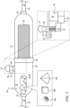
- FIG. 1 is a schematic illustration of an apparatus 20 for shunting blood 22, in accordance with some embodiments of the present invention.
- An inset portion 44 of Fig. 1 shows part of the interior of apparatus 20.
- Apparatus 20 which may be referred to as a "shunt,” comprises a flow-indication chamber 24 shaped to define an entry port 26 and an exit port 28. Blood 22 enters flow-indication chamber 24 via entry port 26, flows through the flow-indication chamber, and exits the flow-indication chamber via exit port 28.
- entry port 26 is configured to couple to an entry tube 30 (or any other entry conduit, such as a catheter) through which blood 22 flows to apparatus 20.
- entry tube 30 may be fittingly inserted into entry port 26, or the entry port may be fittingly inserted into the entry tube.
- apparatus 20 further comprises a filter chamber 32 configured to couple to flow-indication chamber 24 and to hold a blood filter 34 in filter chamber 32.
- Blood filter 34 may be secured within the filter chamber using any suitable structural components, such as a plurality of ribs 86 as shown in Fig. 3 , which is described below.
- Filter chamber 32 is shaped to define an entry port 38, through which blood 22 enters the filter chamber, and an exit port 40, through which the blood exits the filter chamber.
- the filter chamber may be coupled to the flow-indication chamber downstream from the flow-indication chamber, such that the blood flows through the filter chamber after flowing through the flow-indication chamber.
- exit port 40 is configured to couple to an exit tube 42 (or any other exit conduit, such as a catheter), which carries the blood from apparatus 20.
- the filter chamber may be coupled to the flow-indication chamber upstream from the flow-indication chamber.
- a single common port may function as both exit port 40 and entry port 26.
- entry port 38 of the filter chamber is configured to couple to entry tube 30, and exit port 28 of the flow-indication chamber is configured to couple to exit tube 42.
- the flow-indication chamber and filter chamber are coupled to one another via a coupling tube 84.
- apparatus 20 does not comprise filter chamber 32.
- flow-indication chamber 24 may be configured to hold blood filter 34 therein.
- Apparatus 20 may shunt blood 22 between any two suitable blood vessels of a human or animal subject.
- apparatus 20 may shunt blood 22 from any suitable "source” blood vessel of the subject to any suitable "sink” blood vessel of the subject.
- apparatus 20 may shunt blood from an artery of the subject to a vein of the subject, with entry tube 30 delivering blood from the artery and exit tube 42 carrying the blood to the vein.
- apparatus 20 may shunt blood from a carotid artery to a femoral vein during an operation to remove a clot from the carotid artery.
- apparatus 20 may shunt blood from a higher-pressure artery to a lower-pressure artery.
- the upstream end of entry tube 30 is coupled to the source blood vessel (e.g., via a stopcock and/or any other suitable equipment), and the downstream end of the entry tube is coupled to the entry port of apparatus 20 (e.g., entry port 26, for embodiments in which the flow-indication chamber is upstream from the filter chamber).
- the upstream end of exit tube 42 is coupled to the exit port of apparatus 20 (e.g., exit port 40, for embodiments in which the flow-indication chamber is upstream from the filter chamber), and the downstream end of the exit tube is coupled to the sink blood vessel (e.g., via a stopcock and/or any other suitable equipment). Subsequently, blood flows from the source blood vessel to the sink blood vessel via apparatus 20.
- Apparatus 20 further comprises one or more moveable objects 46 disposed within flow-indication chamber 24 and configured to move in response to the flowing of blood 22 from entry port 26 to exit port 28.
- At least a portion of the wall 52 of the flow-indication chamber is transparent so as to expose moveable objects 46 to sight.
- wall 52 may be entirely transparent, as shown in Fig. 3 (described below).
- the wall may comprise at least one transparent window 50.
- the physician may readily check the rate of blood flow through the flow-indication chamber, by observing the degree of movement of moveable objects 46.
- the transparent portion of wall 52 comprises a magnifying lens, configured to magnify moveable objects 46.
- moveable objects 46 comprise a plurality of beads 48, which rotate and/or change position as the blood flows.
- beads 48 have a density less than that of blood 22, such that the beads remain suspended in the blood.
- Beads 48 may comprise any suitable hemocompatible material such as a metal, plastic, wood, latex, synthetic rubber, or any combination of the above.
- each of the beads may have any suitable shape.
- beads 48 may comprise at least one spherical bead 48a.
- beads 48 may comprise at least one bead comprising multiple faces; such a bead may move more in response to the blood flow, relative to spherical bead 48a, due to the greater force applied to the bead by the blood.
- Example of beads comprising multiple faces include a cubical bead 48b and a pyramidical bead 48c.
- each of the beads is coated with an anticoagulant, such as heparin.
- exit port 28 is covered with a filter configured to inhibit any of the beads from passing through.
- filter chamber 32 may be coupled to the flow-indication chamber downstream from the flow-indication chamber, such that any beads that pass through exit port 28 are filtered from the blood by filter 34.
- FIG. 2 is a schematic illustration of apparatus 20, in accordance with some embodiments of the present invention.
- An inset portion 58 of Fig. 2 shows part of the interior of apparatus 20.
- moveable objects 46 comprise a rotational member configured to rotate in response to the blood exerting a force on the rotational member.
- moveable objects 46 may comprise a wheel 54 comprising a plurality of spokes 56 (which may also be referred to as "radial members") and configured to rotate in response to blood 22 exerting a force on spokes 56.
- spokes 56 which may also be referred to as "radial members"
- the length of each spoke 56 may be greater than 0.6 cm, and/or the width of each spoke may be greater than 0.3 cm.
- the length of each spoke 56 may be less than 3.8 cm, and/or the width of each spoke may be less than 1.3 cm.
- inset portion 58 demarcates the unimpeded path 60 of the blood, i.e., the path from entry port 26 to exit port 28 that the blood would follow in the absence of wheel 54.
- wheel 54 is positioned relative to the entry and exit ports such that each spoke, when perpendicular to path 60 at any point along the path, intersects the path.
- the flow of blood through the flow-indication chamber generally keeps the wheel rotating in a single direction. For example, in Fig. 2 , the wheel rotates clockwise, as indicated by a rotation indicator 55.
- the most proximal point on the spoke that intersects path 60 may be located between 50% and 80% of the length of the spoke from the proximal end of the spoke. (For example, if the spoke is 3 cm long, the most proximal point on the spoke that intersects path 60 may be located between 1.5 and 2.4 cm from the proximal end of the spoke.)
- this positioning of the wheel may increase the rotational force to which the wheel is subjected.
- the internal walls 61 of flow-indication chamber 24 constrict the space within the chamber in which the blood can flow, such that the blood follows path 60 at a greater speed and hence, applies greater force to the rotational member.
- wheel 54 is mounted onto a shaft 64 (i.e., shaft 64 passes through hub 62), such that the wheel rotates about the shaft.
- Shaft 64 is coupled at each of its ends to wall 52.
- the rotational member (e.g., wheel 54) may be any suitable color, including a color that contrasts with that of blood, as described above for beads 48 ( Fig. 1 ).
- Doppler ultrasound is used to measure the rate of blood flow.
- a fixture shaped to define a socket, may be fitted over one of the tubes, and a standard Doppler ultrasound probe may be inserted into the socket.
- apparatus 20 further comprises a valve 66 configured to regulate the flow of blood through the flow-indication chamber.
- a physician may control the rate at which blood is shunted.
- valve 66 comprises a pushable element 68 passing through wall 52 and configured to cover entry port 26 or exit port 28 upon being pushed into the flow-indication chamber.
- a gasket 76 (made of rubber, for example) seals the aperture in wall 52 through which the pushable element passes, such that blood does not leak through the wall.
- valve 66 further comprises a spring 78 coupled to the pushable element (e.g., by virtue of being coupled to a ledge 82 coupled to the pushable element) and to an inner wall of the flow-indication chamber (e.g., the inside of wall 52).
- Spring 78 is configured to inhibit the pushable element from covering the entry port or exit port in the absence of any pushing force applied to the pushable element.
- spring 78 comprises a tension spring 80.
- spring 80 In the absence of any pushing force, spring 80 is maximally compressed, such that the tension spring holds the pushable element in its outermost position.
- pushable element 68 comprises a neck 70 and a foot 72, which protrudes from the end of neck 70 that is inside the flow-indication chamber. As neck 70 is pushed further into the flow-indication chamber, foot 72 covers a greater portion of the entry port or exit port, thereby slowing the flow of blood. Upon the neck being maximally pushed, foot 72 completely covers the port, such that the flow is stopped.
- the opposite end of neck 70 which is outside the flow-indication chamber, may terminate at a head 74, which is wider than the neck and thus facilitates the pushing of the neck into the flow-indication chamber.
- valve 66 comprises a pullable element passing through wall 52 and configured to cover entry port 26 or exit port 28 upon being pulled.
- valve 66 may also be combined with any other suitable embodiment of moveable objects 46, such as the embodiment of Fig. 2 .
- FIG. 3 is a schematic illustration of apparatus 20, in accordance with some embodiments of the present invention.
- apparatus 20 comprises tube constrictor 88, which may also be referred to as a "locking clip.”
- Tube constrictor 88 comprises a first appendage 90a, shaped to define a first aperture 92a, and a second appendage 90b, shaped to define a second aperture 92b.
- tube constrictor 88 is configured to control the rate of blood flow through a tube passing through apertures 92a and 92b by constricting the tube with varying degrees of constriction.
- apparatus 20 need not necessarily comprise valve 66 ( Fig. 1 ).
- tube constrictor 88 may provide two degrees of constriction: no (0%) constriction, and full (100%) or partial (e.g., 80%-90%) constriction.
- tube constrictor 88 may provide three or more degrees of constriction.
- An example of four degrees of constriction is 0%, 20%-40% (e.g., 33%), 60%-80% (e.g., 66%), and 90%-100%.
- the tube may be considered to be constricted by x% if the rate of blood flow through the tube is (100-x)% of what the rate would be if the tube were not constricted at all.)
- flow-indication chamber 24 is coupled to filter chamber 32 via coupling tube 84, and tube constrictor 88 is configured to constrict the coupling tube.
- tube constrictor 88 is configured to constrict the coupling tube.
- first appendage 90a and second appendage 90b protrude from filter chamber 32 in the upstream direction, i.e., the first and second appendages protrude beyond entry port 38, and coupling tube 84 carry blood to entry port 38 through the first and second apertures.
- the first and second appendages may protrude from flow-indication chamber 24 in the downstream direction, i.e., the first and second appendages may protrude beyond exit port 28, and coupling tube 84 may carry blood from exit port 28 through the first and second apertures.
- tube constrictor 88 is configured to constrict entry tube 30.
- first appendage 90a and second appendage 90b protrude from flow-indication chamber 24 in the upstream direction, i.e., the first and second appendages protrude beyond entry port 26, and entry tube 30 carries blood to entry port 26 through the first and second apertures.
- flow-indication chamber 24 may be coupled to filter chamber 32 as in Figs. 1-2 , or filter chamber 32 may be omitted.
- tube constrictor 88 is configured to constrict exit tube 42.
- first appendage 90a and second appendage 90b protrude from filter chamber 32 in the downstream direction, i.e., the first and second appendages protrude beyond exit port 40, and exit tube 42 carries blood from exit port 40 through the first and second apertures.
- flow-indication chamber 24 may be coupled to filter chamber 32 as in Figs. 1-2 , or flow-indication chamber 24 may be omitted.
- the flow-indication chamber may contain any suitable moveable objects 46, such as wheel 54 or beads 48 ( Fig. 1 ).
- the first and second appendages are continuous with the wall of the chamber from which the appendages protrude, i.e., the wall extends beyond the chamber so as to define the appendages.
- the appendages are coupled to the wall of the chamber, e.g., using any suitable adhesive.
- each appendage comprises a back arm 100, which protrudes from the chamber, and a front arm 102, which is angled (e.g., at approximately 90 degrees) with respect to back arm 100 and is shaped to define the aperture through which the tube passes.
- inset portion 110 of Fig. 3 which shows the back of front arm 102 of first appendage 90a, i.e., the surface of the front arm that faces second appendage 90b.
- first appendage 90a e.g., front arm 102 of the first appendage
- second appendage 90b e.g., front arm 102 of the second appendage
- second row 94b is configured to interlock with first row 94a at multiple different relative positions of the first appendage and second appendage. In these different positions, second aperture 92b is aligned with first aperture 92a with different respective degrees of alignment such that coupling tube 84 (or any other tube passing through the apertures) is constricted with different respective degrees of constriction.
- Figs. 4A-B are schematic illustrations of tube constrictor 88, in accordance with some embodiments of the present invention.
- the first and second appendages are at a first relative position in which second aperture 92b is aligned with first aperture 92a, such that coupling tube 84 is not constricted. Subsequently, one or both of the appendages may be shifted such that the appendages assume a second relative position in which the two apertures are less aligned with one another, and hence tube 84 is mostly constricted, as shown in Fig. 4B .
- each tooth 96 is angled backward (e.g., toward back arm 100 of the appendage), such that the tooth comprises a longer front edge 104 and a shorter back edge 106.
- the tube may be constricted by advancing the two rows of teeth relative to one another, e.g., by pushing at least one front arm 102 toward the back arm 100 of the other appendage.
- the appendages may be pinched together, e.g., using a forefinger placed on one back arm 100 and a thumb placed on the other back arm.
- front edges 104 slide across each other, until the rows of teeth interlock at the next position by virtue of the contact between back edges 106, which inhibits the rows from sliding backward.
- each tooth 96 is angled forward, toward the tip of the appendage.
- the tube may be constricted by moving at least one row of teeth backward relative to the other row of teeth, e.g., by pulling at least one front arm 102 away from the back arm 100 of the other appendage.
- the first and second appendages are configured to revert to a default relative position, in which the tube is not constricted, upon a release of first row 94a and second row 94b from one another, as indicated in Fig. 4B by release indicators 108.
- at least one of the appendages is elastic, such that any movement from the default relative position causes the appendage to store elastic energy that, upon release of the rows from one another, causes the appendage to revert to the default position.
- the first and second appendages may revert to their default relative position due to elastic energy stored in the wall of the tube while the tube is constricted.
- appendages may be shaped to define fewer teeth than are shown in the figures.
- one appendage may be shaped to define a single tooth, and the other appendage may be shaped to define N ⁇ 2 teeth, such that N degrees of constriction are provided.
- the tube is not completely constricted in any of the positions in which the rows of teeth interlock with one another.
- the tube may remain partly (e.g., 10%-20%) unconstricted.
- full constriction of the tube requires that the physician continuously apply a force to one or both of the appendages, such that the physician is unlikely to forget that the flow has been stopped.
- full constriction of the tube may require a continuous pinching of the appendages. In the absence of a pinching force, the elastic energy stored in the appendages and/or the wall of the tube causes the appendages to revert to the most constricted interlocked position.
- the most constricted interlocked position is that in which the frontmost tooth of one appendage locks against the backmost tooth of the other appendage.
- the most constricted interlocked position is that in which the frontmost tooth of one appendage locks against the frontmost tooth of the other appendage.
- apparatus 20 may comprise any other clamp that protrudes from one of the chambers and is configured to constrict a tube in fluid communication with the chamber.
- the clamp may be continuous with the wall of the chamber from which the clamp protrudes, or coupled to the wall of the chamber.
Landscapes
- Health & Medical Sciences (AREA)
- Heart & Thoracic Surgery (AREA)
- Vascular Medicine (AREA)
- General Health & Medical Sciences (AREA)
- Veterinary Medicine (AREA)
- Engineering & Computer Science (AREA)
- Biomedical Technology (AREA)
- Public Health (AREA)
- Life Sciences & Earth Sciences (AREA)
- Animal Behavior & Ethology (AREA)
- Anesthesiology (AREA)
- Hematology (AREA)
- Cardiology (AREA)
- Physics & Mathematics (AREA)
- Fluid Mechanics (AREA)
- Pulmonology (AREA)
- Gastroenterology & Hepatology (AREA)
- Oral & Maxillofacial Surgery (AREA)
- Transplantation (AREA)
- External Artificial Organs (AREA)
- Prostheses (AREA)
Claims (15)
- Appareil (88) destiné à être utilisé avec un tube (30, 42, 84) destiné à transporter du sang, l'appareil comprenant :une chambre (24, 32) conformée pour définir un orifice de fluide (26, 28, 38, 40) ;un premier appendice (90a) faisant saillie, depuis la chambre (24, 32), au-delà de l'orifice de fluide (26, 28, 38, 40) et conformé pour définir une première ouverture (92a) et une première rangée (94a) d'une ou plusieurs dents (96) ; etun deuxième appendice (90b) faisant saillie, depuis la chambre (24, 32), au-delà de l'orifice de fluide (26, 28, 38, 40) et conformé pour définir une deuxième ouverture (92b) et une deuxième rangée (94b) d'une ou plusieurs dents (96) parallèles à la première rangée (94a) de dents (96),l'orifice de fluide (26, 28, 38, 40) étant configuré pour s'accoupler au tube (30, 42, 84) tandis que le tube (30, 42, 84) passe à travers la première ouverture (92a) et la deuxième ouverture (92b), de sorte que le tube (30, 42, 84) transporte le sang vers ou depuis l'orifice de fluide (26, 28, 38, 40) à travers la première ouverture (92a) et la deuxième ouverture (92b), etla deuxième rangée (94b) étant configurée pour s'emboîter avec la première rangée (94a) en plusieurs positions relatives différentes du premier appendice (90a) et du deuxième appendice (90b) auxquelles la deuxième ouverture (92b) est alignée avec la première ouverture (92a) avec différents degrés respectifs d'alignement, de telle sorte que le tube (30, 42, 84) soit resserré avec différents degrés respectifs de resserrage.
- Appareil (88) selon la revendication 1, la chambre (32) étant configurée pour contenir un filtre sanguin (34) à l'intérieur.
- Appareil (88) selon la revendication 1, comprenant en outre un ou plusieurs objets mobiles (46) disposés à l'intérieur de la chambre (24) et configurés pour se déplacer en réponse à un écoulement du sang à travers la chambre (24), au moins une partie d'une paroi (52) de la chambre (24) étant transparente de manière à présenter les objets mobiles (46) à la vue.
- Appareil (88) selon l'une quelconque des revendications 1 à 3, le tube (30, 42, 84) étant resserré avec trois degrés de resserrage ou plus.
- Appareil (88) selon l'une quelconque des revendications 1 à 3, le premier appendice (90a) et le deuxième appendice (90b) étant configurés pour revenir à une position relative par défaut, à laquelle le tube (30, 42, 84) n'est pas resserré, lorsque la première rangée (94a) et la deuxième rangée (94b) sont libérées l'une de l'autre.
- Appareil (88) selon l'une quelconque des revendications 1 à 3,le premier appendice (90a) comprenant un premier bras arrière (100), qui fait saillie de la chambre (24, 32), et un premier bras avant (102), qui est incliné par rapport au premier bras arrière (100) et qui est conformé pour définir la première ouverture (92a) et la première rangée (94a) de dents (96), etle deuxième appendice (90b) comprenant un deuxième bras arrière (100), qui fait saillie de la chambre (24, 32), et un deuxième bras avant (102), qui est incliné par rapport au deuxième bras arrière (100) et qui est conformé pour définir la deuxième ouverture (92b) et la deuxième rangée (94b) de dents (96).
- Appareil (88) selon la revendication 6, chacune des dents (96) de la première rangée (94a) étant inclinée vers le premier bras arrière (100) et chacune des dents (96) de la deuxième rangée (94b) étant inclinée vers le deuxième bras arrière (100), de telle sorte que la première rangée (94a) et la deuxième rangée (94b) soient configurées pour s'emboîter à une position suivante, ce qui resserre le tube (30, 42, 84), lorsque la première rangée (94a) et la deuxième rangée (94b) sont avancées l'une par rapport à l'autre.
- Appareil (88) selon la revendication 7,
la première rangée (94a) et la deuxième rangée (94b) étant configurées pour avancer l'une par rapport à l'autre lorsque le premier appendice (90a) et le deuxième appendice (90b) sont pincés conjointement. - Appareil (88) selon l'une quelconque des revendications 1 à 3, le tube (30, 42, 84) n'étant pas complètement resserré, de sorte que l'écoulement du sang n'est pas arrêté, à aucune des positions.
- Procédé d'utilisation avec un tube (30, 42, 84) transportant du sang vers ou depuis un orifice de fluide (26, 28, 38, 40) d'une chambre (24, 32), le procédé comprenant les étapes suivantes :faire coulisser un premier appendice (90a), qui fait saillie de la chambre (24, 32) au-delà de l'orifice de fluide (26, 28, 38, 40) et qui est conformé pour définir une première ouverture (92a) et une première rangée (94a) d'une ou plusieurs dents (96), sur un deuxième appendice (90b), qui fait saillie de la chambre (24, 32) au-delà de l'orifice de fluide (26, 28, 38, 40) et qui est conformé pour définir une deuxième ouverture (92b) et une deuxième rangée (94b) d'une ou plusieurs dents (96) parallèles à la première rangée (94a) de dents (96), de sorte que la deuxième rangée (94b) s'emboîte avec la première rangée (94a) à une position relative du premier appendice (90a) et du deuxième appendice (90b) à laquelle la deuxième ouverture (92b) est désalignée avec la première ouverture (92a), ce qui resserre le tube (30, 42, 84) tandis que le tube (30, 42, 84) passe à travers la première ouverture (92a) et la deuxième ouverture (92b) ; etaprès avoir resserré le tube (30, 42, 84), libérer la première rangée (94a) et la deuxième rangée (94b) l'une de l'autre, ce qui ramène le premier appendice (90a) et le deuxième appendice (90b) à une position relative par défaut à laquelle le tube (30, 42, 84) n'est pas resserré.
- Procédé selon la revendication 10, la chambre (32) contenant un filtre sanguin (34).
- Procédé selon la revendication 10, un ou plusieurs objets mobiles (46) étant disposés à l'intérieur de la chambre (24) et étant configurés pour se déplacer en réponse à un écoulement du sang à travers la chambre (24), au moins une partie d'une paroi (52) de la chambre (24) étant transparente de manière à présenter les objets mobiles (46) à la vue.
- Procédé selon l'une quelconque des revendications 10 à 12,le premier appendice (90a) comprenant un premier bras arrière (100), qui fait saillie de la chambre (24, 32), et un premier bras avant (102), qui est incliné par rapport au premier bras arrière (100) et qui est conformé pour définir la première ouverture (92a) et la première rangée (94a) de dents (96), etle deuxième appendice (90b) comprenant un deuxième bras arrière (100), qui fait saillie de la chambre (24, 32), et un deuxième bras avant (102), qui est incliné par rapport au deuxième bras arrière (100) et qui est conformé pour définir la deuxième ouverture (92b) et la deuxième rangée (94b) de dents (96).
- Procédé selon la revendication 13, chacune des dents (96) de la première rangée (94a) étant inclinée vers le premier bras arrière (100) et chacune des dents (96) de la deuxième rangée (94b) étant inclinée vers le deuxième bras arrière (100), et le coulissement du premier appendice (90a) sur le deuxième appendice (90b) comprenant l'avancement de la première rangée (94a) et de la deuxième rangée (94b) l'une par rapport à l'autre.
- Procédé selon la revendication 14, l'avancement de la première rangée (94a) et de la deuxième rangée (94b) l'une par rapport à l'autre comprenant l'avancement de la première rangée (94a) et de la deuxième rangée (94b) l'une par rapport à l'autre par pincement conjoint du premier appendice (90a) et du deuxième appendice (90b).
Priority Applications (1)
| Application Number | Priority Date | Filing Date | Title |
|---|---|---|---|
| EP25177017.8A EP4578483A3 (fr) | 2021-01-17 | 2022-01-16 | Dérivations avec indicateurs de débit sanguin |
Applications Claiming Priority (2)
| Application Number | Priority Date | Filing Date | Title |
|---|---|---|---|
| US202163138451P | 2021-01-17 | 2021-01-17 | |
| PCT/IB2022/050329 WO2022153259A1 (fr) | 2021-01-17 | 2022-01-16 | Dérivations avec indicateurs de flux sanguin |
Related Child Applications (2)
| Application Number | Title | Priority Date | Filing Date |
|---|---|---|---|
| EP25177017.8A Division-Into EP4578483A3 (fr) | 2021-01-17 | 2022-01-16 | Dérivations avec indicateurs de débit sanguin |
| EP25177017.8A Division EP4578483A3 (fr) | 2021-01-17 | 2022-01-16 | Dérivations avec indicateurs de débit sanguin |
Publications (4)
| Publication Number | Publication Date |
|---|---|
| EP4277676A1 EP4277676A1 (fr) | 2023-11-22 |
| EP4277676A4 EP4277676A4 (fr) | 2024-05-08 |
| EP4277676B1 true EP4277676B1 (fr) | 2025-07-02 |
| EP4277676C0 EP4277676C0 (fr) | 2025-07-02 |
Family
ID=82406789
Family Applications (2)
| Application Number | Title | Priority Date | Filing Date |
|---|---|---|---|
| EP25177017.8A Pending EP4578483A3 (fr) | 2021-01-17 | 2022-01-16 | Dérivations avec indicateurs de débit sanguin |
| EP22739245.3A Active EP4277676B1 (fr) | 2021-01-17 | 2022-01-16 | Dérivations avec indicateurs de flux sanguin |
Family Applications Before (1)
| Application Number | Title | Priority Date | Filing Date |
|---|---|---|---|
| EP25177017.8A Pending EP4578483A3 (fr) | 2021-01-17 | 2022-01-16 | Dérivations avec indicateurs de débit sanguin |
Country Status (6)
| Country | Link |
|---|---|
| US (3) | US11844893B2 (fr) |
| EP (2) | EP4578483A3 (fr) |
| JP (2) | JP7449627B2 (fr) |
| CN (2) | CN117202872B (fr) |
| ES (1) | ES3036583T3 (fr) |
| WO (1) | WO2022153259A1 (fr) |
Families Citing this family (3)
| Publication number | Priority date | Publication date | Assignee | Title |
|---|---|---|---|---|
| US10925709B2 (en) * | 2015-04-30 | 2021-02-23 | Silk Road Medical, Inc. | Systems and methods for transcatheter aortic valve treatment |
| JP7576884B2 (ja) * | 2021-03-25 | 2024-11-01 | インスパイア エム.ディー リミテッド | 動脈系と静脈系の間で血液をシャントする装置 |
| WO2025160308A1 (fr) * | 2024-01-24 | 2025-07-31 | Boston Scientific Scimed, Inc. | Dispositifs médicaux à vidange passive et active |
Family Cites Families (142)
| Publication number | Priority date | Publication date | Assignee | Title |
|---|---|---|---|---|
| US2847969A (en) * | 1956-07-11 | 1958-08-19 | Walter S Roboski | Fluid flow indicator |
| US3185128A (en) * | 1963-06-06 | 1965-05-25 | Dover Corp | Sight-glass indicator or the like |
| GB1271361A (en) | 1968-07-19 | 1972-04-19 | Raymond George Gosling | Means and method for signalling change of fluid flow |
| US3889687A (en) * | 1974-01-31 | 1975-06-17 | Donald L Harris | Shunt system for the transport of cerebrospinal fluid |
| JPS5542266Y2 (fr) * | 1975-03-17 | 1980-10-03 | ||
| JPS6223488Y2 (fr) * | 1981-04-16 | 1987-06-15 | ||
| CA1177718A (fr) * | 1981-04-16 | 1984-11-13 | Masaru Kawahashi | Tubulure utilisee dans le traitement des liquides organiques |
| US4543095A (en) | 1983-10-14 | 1985-09-24 | E. R. Squibb & Sons, Inc. | Visual flow indicator |
| US4661097A (en) | 1984-06-01 | 1987-04-28 | The Johns Hopkins University | Method for clearing a gas bubble from a positive displacement pump contained within a fluid dispensing system |
| AU591883B2 (en) * | 1984-12-03 | 1989-12-21 | Baxter International Inc. | Housing enabling passive mixing of a beneficial agent with a diluent |
| US4874359A (en) | 1987-12-14 | 1989-10-17 | White Frederick R | Power infuser |
| JPH065636Y2 (ja) * | 1988-03-07 | 1994-02-09 | ミドリ安全工業株式会社 | フローインジケータ |
| US5632746A (en) * | 1989-08-16 | 1997-05-27 | Medtronic, Inc. | Device or apparatus for manipulating matter |
| US5437290A (en) | 1991-09-06 | 1995-08-01 | Board Of Trustees Of The Leland Stanford Jr. University | System and method for monitoring intraluminal device position |
| US5374239A (en) * | 1992-08-04 | 1994-12-20 | Metatech Corporation | Arterial shunt with blood flow indicator |
| US5334163A (en) * | 1992-09-16 | 1994-08-02 | Sinnett Kevin B | Apparatus for preparing and administering a dose of a fluid mixture for injection into body tissue |
| US5395105A (en) | 1993-11-05 | 1995-03-07 | Thommen, Jr.; Robert A. | Safety net system |
| US5954691A (en) | 1995-06-07 | 1999-09-21 | Biolink Corporation | Hemodialysis access apparatus |
| US6312454B1 (en) | 1996-06-13 | 2001-11-06 | Nitinol Devices & Components | Stent assembly |
| US5843244A (en) | 1996-06-13 | 1998-12-01 | Nitinol Devices And Components | Shape memory alloy treatment |
| US5876367A (en) | 1996-12-05 | 1999-03-02 | Embol-X, Inc. | Cerebral protection during carotid endarterectomy and downstream vascular protection during other surgeries |
| US6295989B1 (en) | 1997-02-06 | 2001-10-02 | Arteria Medical Science, Inc. | ICA angioplasty with cerebral protection |
| US6312455B2 (en) | 1997-04-25 | 2001-11-06 | Nitinol Devices & Components | Stent |
| EP2133030A1 (fr) | 1997-06-27 | 2009-12-16 | The Trustees of Columbia University of the City of New York | Appareil de réparation de valvules cardiaques |
| US6503271B2 (en) | 1998-01-09 | 2003-01-07 | Cordis Corporation | Intravascular device with improved radiopacity |
| US6129755A (en) | 1998-01-09 | 2000-10-10 | Nitinol Development Corporation | Intravascular stent having an improved strut configuration |
| US6425898B1 (en) | 1998-03-13 | 2002-07-30 | Cordis Corporation | Delivery apparatus for a self-expanding stent |
| US6423032B2 (en) | 1998-03-13 | 2002-07-23 | Arteria Medical Science, Inc. | Apparatus and methods for reducing embolization during treatment of carotid artery disease |
| AR017498A1 (es) | 1998-03-13 | 2001-09-12 | Arteria Medical Science Llc | Dispositivo para proteccion contra embolizaciones, en angioplastia de carotida |
| US6019778A (en) | 1998-03-13 | 2000-02-01 | Cordis Corporation | Delivery apparatus for a self-expanding stent |
| US6540712B1 (en) | 1998-03-13 | 2003-04-01 | Arteria Medical Science, Inc. | Methods and low profile apparatus for reducing embolization during treatment of carotid artery disease |
| US6206868B1 (en) | 1998-03-13 | 2001-03-27 | Arteria Medical Science, Inc. | Protective device and method against embolization during treatment of carotid artery disease |
| US6071269A (en) | 1998-05-13 | 2000-06-06 | Medisystems Technology Corporation | Blood set and chamber |
| US6645222B1 (en) | 1998-05-13 | 2003-11-11 | Arteria Medical Science, Inc. | Puncture resistant branch artery occlusion device and methods of use |
| US6582396B1 (en) | 1998-05-13 | 2003-06-24 | Arteria Medical Science, Inc. | Puncture resistant balloon for use in carotid artery procedures and methods of use |
| US6908474B2 (en) | 1998-05-13 | 2005-06-21 | Gore Enterprise Holdings, Inc. | Apparatus and methods for reducing embolization during treatment of carotid artery disease |
| US6936060B2 (en) | 1998-05-13 | 2005-08-30 | Arteria Medical Sciences, Inc. | Apparatus and methods for removing emboli during a surgical procedure |
| JP4093383B2 (ja) | 1998-06-05 | 2008-06-04 | Nskワーナー株式会社 | ダンパー付ロックアップピストン |
| US6019772A (en) | 1998-09-21 | 2000-02-01 | Arteria Medical Sciences, Inc. | Atherectomy device |
| US6235042B1 (en) | 1998-09-21 | 2001-05-22 | Arteria Medical Science, Inc. | Atherectomy device |
| US6371904B1 (en) | 1998-12-24 | 2002-04-16 | Vivant Medical, Inc. | Subcutaneous cavity marking device and method |
| US6632236B2 (en) | 1999-03-12 | 2003-10-14 | Arteria Medical Science, Inc. | Catheter having radially expandable main body |
| US6682505B2 (en) | 1999-03-12 | 2004-01-27 | Arteria Medical Science, Inc. | Catheter for removing emboli from saphenous vein grafts and native coronary arteries |
| US6641573B1 (en) | 1999-03-25 | 2003-11-04 | Arteria Medical Science, Inc. | Device and method of guide wire balloon inflation and deflation to prevent cerebral embolization during carotid stenting |
| US6514236B1 (en) | 1999-04-23 | 2003-02-04 | Alexander A. Stratienko | Method for treating a cardiovascular condition |
| EP1072282A1 (fr) | 1999-07-19 | 2001-01-31 | EndoArt S.A. | Dispositif de régulation de débit |
| US6726659B1 (en) | 1999-12-09 | 2004-04-27 | John E. Stocking | Catheter assembly having a fenestrated dilator |
| US6942688B2 (en) | 2000-02-29 | 2005-09-13 | Cordis Corporation | Stent delivery system having delivery catheter member with a clear transition zone |
| US20050113798A1 (en) | 2000-07-21 | 2005-05-26 | Slater Charles R. | Methods and apparatus for treating the interior of a blood vessel |
| US6743219B1 (en) | 2000-08-02 | 2004-06-01 | Cordis Corporation | Delivery apparatus for a self-expanding stent |
| US6863685B2 (en) | 2001-03-29 | 2005-03-08 | Cordis Corporation | Radiopacity intraluminal medical device |
| DE10218846C1 (de) | 2002-04-27 | 2003-09-18 | Fresenius Medical Care De Gmbh | Verfahren zur Unterbrechung oder Fortführung einer extrakorporalen Blutbehandlung mit veränderten Flussraten und Vorrichtung zur extrakorporalen Blutbehandlung |
| US7223253B2 (en) | 2002-07-29 | 2007-05-29 | Gore Enterprise Holdings, Inc. | Blood aspiration system and methods of use |
| EP1578484A4 (fr) | 2002-12-16 | 2007-05-30 | Meagan Medical Inc | Procede et appareil permettant de commander la profondeur d'applications percutanees |
| US6859986B2 (en) | 2003-02-20 | 2005-03-01 | Cordis Corporation | Method system for loading a self-expanding stent |
| US7344527B2 (en) | 2003-11-19 | 2008-03-18 | Medical Components, Inc. | Luer with integrated clamp |
| CN100534392C (zh) | 2003-11-21 | 2009-09-02 | 戴维·W·常 | 用于治疗颈动脉的器械 |
| WO2005051206A1 (fr) | 2003-11-21 | 2005-06-09 | Vnus Medical Technologies, Inc. | Methode et appareil de traitement d'artere carotide |
| US7063685B2 (en) | 2004-05-12 | 2006-06-20 | C. R. Bard, Inc. | Hemostasis valve for a catheter |
| US7303175B2 (en) | 2004-07-16 | 2007-12-04 | Cardinal Health 303, Inc. | Automatic clamp apparatus having lateral motion resistance for IV infusion sets |
| US7879011B2 (en) | 2004-11-18 | 2011-02-01 | Silk Road Medical, Inc. | Endoluminal delivery of anesthesia |
| US20070142852A1 (en) | 2005-12-21 | 2007-06-21 | Manoa Medical, Inc., A Delaware Corporation | Tissue cutting device |
| US9011467B2 (en) | 2008-08-13 | 2015-04-21 | Silk Road Medical, Inc. | Suture delivery device |
| US8858490B2 (en) | 2007-07-18 | 2014-10-14 | Silk Road Medical, Inc. | Systems and methods for treating a carotid artery |
| US8545432B2 (en) * | 2009-06-03 | 2013-10-01 | Silk Road Medical, Inc. | System and methods for controlling retrograde carotid arterial blood flow |
| EP2497520B1 (fr) | 2007-07-18 | 2022-04-13 | Silk Road Medical, Inc. | Systèmes pour établir un flux sanguin rétrograde dans l'artère carotide |
| US7828528B2 (en) * | 2007-09-06 | 2010-11-09 | Asante Solutions, Inc. | Occlusion sensing system for infusion pumps |
| US8235943B2 (en) | 2007-12-21 | 2012-08-07 | Indian Wells Medical, Inc. | Method and apparatus for prevention of catheter air intake |
| WO2009097274A2 (fr) | 2008-01-29 | 2009-08-06 | Medical Components, Inc. | Ensemble gaine d'introduction doté d'un raccord et procédé de jonction d'un raccord à un tube de gaine |
| EP3789069B1 (fr) | 2008-02-05 | 2024-04-03 | Silk Road Medical, Inc. | Système et procédés de cathéter d'intervention |
| EP2113266A1 (fr) | 2008-04-30 | 2009-11-04 | Gambro Lundia AB | Dispositif de dégazage |
| US8574245B2 (en) | 2008-08-13 | 2013-11-05 | Silk Road Medical, Inc. | Suture delivery device |
| FR2939346B1 (fr) | 2008-12-10 | 2014-09-12 | Sartorius Stedim Biotech Sa | Pincement de fermeture d'un tube souple destine a des applications biopharmaceutiques |
| US10226563B2 (en) | 2008-12-23 | 2019-03-12 | Silk Road Medical, Inc. | Methods and systems for treatment of acute ischemic stroke |
| US20100168682A1 (en) * | 2008-12-31 | 2010-07-01 | Tyco Healthcare Group Lp | Catheter clamping assemblies |
| US20100204684A1 (en) | 2009-01-13 | 2010-08-12 | Garrison Michi E | Methods and systems for performing neurointerventional procedures |
| US20100198158A1 (en) | 2009-01-30 | 2010-08-05 | Loewen John L | Medical apparatus and method of making the same |
| US20110251482A1 (en) | 2009-10-29 | 2011-10-13 | Rox Medical, Inc. | Devices, systems and methods for enhanced visualization of the anatomy of a patient |
| US8545552B2 (en) | 2010-02-26 | 2013-10-01 | Silk Road Medical, Inc. | Systems and methods for transcatheter aortic valve treatment |
| US8758306B2 (en) | 2010-05-17 | 2014-06-24 | Icu Medical, Inc. | Medical connectors and methods of use |
| US9623228B2 (en) | 2010-08-12 | 2017-04-18 | Silk Road Medical, Inc. | Systems and methods for treating a carotid artery |
| TW201225997A (en) | 2010-08-20 | 2012-07-01 | Thoratec Corp | Assembly and method for stabilizing a percutaneous cable |
| EP2754458B1 (fr) | 2011-07-12 | 2017-02-01 | Sorin Group Italia S.r.l. | Réservoir de sang à double chambre |
| EP2739217B1 (fr) | 2011-08-05 | 2022-07-20 | Route 92 Medical, Inc. | Systèmes de traitement d'un accident ischémique cérébral aigu |
| US10779855B2 (en) | 2011-08-05 | 2020-09-22 | Route 92 Medical, Inc. | Methods and systems for treatment of acute ischemic stroke |
| US8951222B2 (en) | 2011-08-10 | 2015-02-10 | Western Vascular Institute | Arterial shunt |
| EP2753375B1 (fr) | 2011-09-09 | 2020-11-04 | Nordic Med -com Aktiebolag | Ensemble introducteur de cathéter |
| KR101333118B1 (ko) | 2011-11-18 | 2013-11-26 | 한국기계연구원 | 수액주입용 선형유량조절장치 |
| US9545472B2 (en) | 2012-03-02 | 2017-01-17 | Medtronic, Inc. | Extracorporeal blood circuit reservoir with angled venous inlet luer port |
| US9084857B2 (en) | 2012-04-16 | 2015-07-21 | W. L. Gore & Associates, Inc. | Single access flow-reversal catheter devices and methods |
| US9060724B2 (en) | 2012-05-30 | 2015-06-23 | Magnolia Medical Technologies, Inc. | Fluid diversion mechanism for bodily-fluid sampling |
| US9101449B2 (en) * | 2012-07-27 | 2015-08-11 | Cook Medical Technologies Llc | Filter removal device |
| US10159479B2 (en) | 2012-08-09 | 2018-12-25 | Silk Road Medical, Inc. | Suture delivery device |
| US9415151B2 (en) | 2012-09-25 | 2016-08-16 | Fresenius Medical Care Holdings, Inc. | Blood flow reversal valves and related systems and methods |
| US10272269B2 (en) | 2012-11-13 | 2019-04-30 | Silk Road Medical, Inc. | Devices and methods for endoluminal delivery of either fluid or energy for denervation |
| CN105050491B (zh) | 2013-01-24 | 2017-07-11 | 格拉夫特沃克斯有限责任公司 | 用于测量穿过管腔的流的方法和装置 |
| EP2967381B1 (fr) | 2013-03-15 | 2018-12-12 | Carlos A. Hakim | Ensemble de soupape de dérivation |
| US20160022292A1 (en) | 2013-03-15 | 2016-01-28 | Crux Biomedical, Inc. | Retrieval and centering device and method with pressure and ultrasound features |
| WO2014160887A2 (fr) | 2013-03-28 | 2014-10-02 | Silk Road Medical, Inc. | Procédés et systèmes pour établir un écoulement sanguin rétrograde dans l'artère carotide |
| WO2014160613A1 (fr) | 2013-03-29 | 2014-10-02 | Silk Road Medical, Inc, | Systèmes et procédés pour une aspiration à partir d'une lumière corporelle |
| US20140303427A1 (en) | 2013-04-09 | 2014-10-09 | Circulite, Inc. | Blood flow system with operator attachable components |
| US9265512B2 (en) | 2013-12-23 | 2016-02-23 | Silk Road Medical, Inc. | Transcarotid neurovascular catheter |
| US20150250470A1 (en) | 2014-03-05 | 2015-09-10 | Coaxis Medical, Inc. | Suture anchoring system and delivery method |
| US9820761B2 (en) | 2014-03-21 | 2017-11-21 | Route 92 Medical, Inc. | Rapid aspiration thrombectomy system and method |
| US9241699B1 (en) | 2014-09-04 | 2016-01-26 | Silk Road Medical, Inc. | Methods and devices for transcarotid access |
| US10182801B2 (en) | 2014-05-16 | 2019-01-22 | Silk Road Medical, Inc. | Vessel access and closure assist system and method |
| ES2967298T3 (es) | 2014-07-28 | 2024-04-29 | Silk Road Medical Inc | Catéter neurovascular transcarotídeo |
| US11027104B2 (en) | 2014-09-04 | 2021-06-08 | Silk Road Medical, Inc. | Methods and devices for transcarotid access |
| JP6640861B2 (ja) | 2015-01-30 | 2020-02-05 | スミスズ メディカル エーエスディー,インコーポレイティド | 解放可能なカテーテルハブ保持具 |
| JP7020920B2 (ja) | 2015-02-24 | 2022-02-16 | シルク・ロード・メディカル・インコーポレイテッド | 縫合糸送達デバイス |
| US10238853B2 (en) | 2015-04-10 | 2019-03-26 | Silk Road Medical, Inc. | Methods and systems for establishing retrograde carotid arterial blood flow |
| US10925709B2 (en) | 2015-04-30 | 2021-02-23 | Silk Road Medical, Inc. | Systems and methods for transcatheter aortic valve treatment |
| CN204709643U (zh) * | 2015-05-27 | 2015-10-21 | 程静娟 | 胸管连接器 |
| WO2017019563A1 (fr) | 2015-07-24 | 2017-02-02 | Route 92 Medical, Inc. | Système et procédés de distribution d'ancrage |
| US10912647B2 (en) * | 2015-08-25 | 2021-02-09 | Innovein, Inc. | Vascular valve prosthesis |
| EP4186470A1 (fr) * | 2015-08-25 | 2023-05-31 | Innovein, Inc. | Prothèse de valvule veineuse |
| US11547415B2 (en) | 2016-07-22 | 2023-01-10 | Route 92 Medical, Inc. | Endovascular interventions in neurovascular anatomy |
| EP4134120A1 (fr) | 2017-01-10 | 2023-02-15 | Route 92 Medical, Inc. | Systèmes de cathéter d'aspiration |
| US10864350B2 (en) | 2017-01-20 | 2020-12-15 | Route 92 Medical, Inc. | Single operator intracranial medical device delivery systems and methods of use |
| JP7430061B2 (ja) | 2017-02-21 | 2024-02-09 | シルク・ロード・メディカル・インコーポレイテッド | 血管インプラント |
| WO2018206747A1 (fr) | 2017-05-12 | 2018-11-15 | National University Of Ireland, Galway | Système et procédé chirurgicaux vasculaires percutanés |
| JP2020527964A (ja) | 2017-07-05 | 2020-09-17 | シルク・ロード・メディカル・インコーポレイテッドSilk Road Medical, Inc. | 経頸動脈アクセスの方法とデバイス |
| CN116250868A (zh) | 2017-09-12 | 2023-06-13 | 木兰医药技术股份有限公司 | 流体控制装置及其使用方法 |
| WO2019089385A1 (fr) | 2017-11-02 | 2019-05-09 | Silk Road Medical, Inc. | Gaine fenêtrée pour protection embolique pendant la revascularisation transcarotidienne de l'artère carotide |
| JP2019154669A (ja) | 2018-03-09 | 2019-09-19 | 日本ゼオン株式会社 | シースハブ用アダプタ部材 |
| EP3768367B1 (fr) | 2018-03-21 | 2024-05-08 | Carefusion 303 Inc. | Dispositif de régulation d'écoulement actionné de manière linéaire pour administration intraveineuse (iv) de liquide |
| CN115999019B (zh) | 2018-05-17 | 2025-05-27 | 92号医疗公司 | 抽吸导管系统和使用方法 |
| US20190380563A1 (en) | 2018-06-14 | 2019-12-19 | Kintur Sanghvi | Introducer sheath having perfusion capabilities and methods of use |
| CN112955207A (zh) | 2018-10-09 | 2021-06-11 | 林弗洛公司 | 用于导管对准的设备和方法 |
| CN113784793B (zh) | 2019-03-11 | 2023-09-19 | 木兰医药技术股份有限公司 | 流体控制装置及其使用方法 |
| US11002585B2 (en) | 2019-03-12 | 2021-05-11 | Juan Carlos Elizalde | Liquid flow indicator device and method of use |
| SG11202109140VA (en) | 2019-03-13 | 2021-09-29 | Abiomed Inc | Dual hub introducer sheath |
| CN209848141U (zh) * | 2019-04-11 | 2019-12-27 | 四川大学华西医院 | 一种可调节式阻断夹 |
| CN113811931B (zh) | 2019-06-20 | 2024-02-02 | 住友电气工业株式会社 | 车载通信系统、交换机装置、功能部、通信控制方法以及通信控制程序 |
| US12582439B2 (en) | 2019-06-21 | 2026-03-24 | Boston Scientific Scimed, Inc. | Transcarotid vascular access sheath |
| US20210001091A1 (en) | 2019-07-01 | 2021-01-07 | Gerald Ernst Schmidt | Remote access vascular and soft tissue tunneling dilator systems and methods of use |
| BR112022000454A2 (pt) | 2019-07-09 | 2022-03-03 | Elixir Medical Corp | Método e dispositivos para aplicação de próteses implantáveis |
| US12465366B2 (en) | 2019-10-31 | 2025-11-11 | Boston Scientific Scimed, Inc. | Systems and methods for neurovascular interventions |
| US20220378565A1 (en) | 2019-11-01 | 2022-12-01 | Silk Road Medical, Inc. | Systems and methods for transcatheter aortic valve treatment |
| WO2021102011A1 (fr) | 2019-11-18 | 2021-05-27 | Silk Road Medical, Inc. | Protection embolique en liaison avec la revascularisation de l'artère transcarotidienne |
| RU2759406C1 (ru) | 2020-03-05 | 2021-11-12 | Игорь Викторович Балязин-Парфенов | Устройство для чрескожного удаления грыж межпозвонковых дисков шейного отдела позвоночника с эндоскопической ассистенцией |
| JP7576884B2 (ja) | 2021-03-25 | 2024-11-01 | インスパイア エム.ディー リミテッド | 動脈系と静脈系の間で血液をシャントする装置 |
-
2022
- 2022-01-16 EP EP25177017.8A patent/EP4578483A3/fr active Pending
- 2022-01-16 CN CN202280008996.3A patent/CN117202872B/zh active Active
- 2022-01-16 WO PCT/IB2022/050329 patent/WO2022153259A1/fr not_active Ceased
- 2022-01-16 JP JP2023542563A patent/JP7449627B2/ja active Active
- 2022-01-16 ES ES22739245T patent/ES3036583T3/es active Active
- 2022-01-16 CN CN202411580875.3A patent/CN119279854A/zh active Pending
- 2022-01-16 US US17/576,953 patent/US11844893B2/en active Active
- 2022-01-16 EP EP22739245.3A patent/EP4277676B1/fr active Active
-
2023
- 2023-10-23 US US18/491,834 patent/US12465674B2/en active Active
-
2024
- 2024-02-26 JP JP2024026477A patent/JP7794484B2/ja active Active
-
2025
- 2025-09-18 US US19/332,152 patent/US20260000820A1/en active Pending
Also Published As
| Publication number | Publication date |
|---|---|
| EP4277676A1 (fr) | 2023-11-22 |
| US20220226556A1 (en) | 2022-07-21 |
| US12465674B2 (en) | 2025-11-11 |
| EP4277676A4 (fr) | 2024-05-08 |
| JP2024061733A (ja) | 2024-05-08 |
| US11844893B2 (en) | 2023-12-19 |
| JP7449627B2 (ja) | 2024-03-14 |
| ES3036583T3 (en) | 2025-09-22 |
| EP4578483A2 (fr) | 2025-07-02 |
| WO2022153259A1 (fr) | 2022-07-21 |
| EP4277676C0 (fr) | 2025-07-02 |
| US20260000820A1 (en) | 2026-01-01 |
| JP7794484B2 (ja) | 2026-01-06 |
| CN119279854A (zh) | 2025-01-10 |
| JP2023552236A (ja) | 2023-12-14 |
| CN117202872B (zh) | 2024-11-26 |
| EP4578483A3 (fr) | 2025-10-01 |
| CN117202872A (zh) | 2023-12-08 |
| US20240042117A1 (en) | 2024-02-08 |
Similar Documents
| Publication | Publication Date | Title |
|---|---|---|
| US12465674B2 (en) | Shunts with blood-flow indicators | |
| US20220233782A1 (en) | Volume monitoring systems | |
| ES2227751T3 (es) | Dispositivo para vigilar una bomba de infusion. | |
| US5098376A (en) | Apparatus and methods for furling and introducing an extrapulmonary blood gas exchange device | |
| JP4297639B2 (ja) | 自己閉塞カテーテル | |
| US4645496A (en) | Continuous catheter flushing flow control device | |
| CA1096264A (fr) | Traduction non-disponible | |
| US8123727B2 (en) | Flush entrance hemostasis valve with unobstructed passageway | |
| US4457487A (en) | Flushing device | |
| DK169832B1 (da) | Ventil til tilvejebringelse og fastholdelse af en indgivelsesstrømningsstørrelse i et intravenøst system | |
| JPH04212375A (ja) | 弁と弁オープナを備えたカテーテルアセンブリー | |
| US8926571B1 (en) | Hemodialysis catheter assembly | |
| GB2044107A (en) | Intravascular catheter assembly | |
| JPH0123142B2 (fr) | ||
| IL46521A (en) | Unit for infusing a liquid drug continuously into a patient at a controlled rate | |
| US5122121A (en) | Safety needle assembly | |
| EP0989869A1 (fr) | Valve a fente non effractive et commande variable d'ouverture et de fermeture de ladite fente | |
| US4210178A (en) | Perpetual by-pass flushing device | |
| US4458877A (en) | Flushing apparatus | |
| HK40119372A (zh) | 具有血流指示器的分流器 | |
| HK40100855A (zh) | 具有血流指示器的分流器 | |
| HK40100855B (zh) | 具有血流指示器的分流器 | |
| CN223208762U (zh) | 一种滤膜可调式双通道药液过滤器的精密输液器 | |
| CN223959065U (zh) | 一种护理静脉置管保护套 | |
| CN213552091U (zh) | 可调压力的肝门阻断器 |
Legal Events
| Date | Code | Title | Description |
|---|---|---|---|
| STAA | Information on the status of an ep patent application or granted ep patent |
Free format text: STATUS: THE INTERNATIONAL PUBLICATION HAS BEEN MADE |
|
| PUAI | Public reference made under article 153(3) epc to a published international application that has entered the european phase |
Free format text: ORIGINAL CODE: 0009012 |
|
| STAA | Information on the status of an ep patent application or granted ep patent |
Free format text: STATUS: REQUEST FOR EXAMINATION WAS MADE |
|
| 17P | Request for examination filed |
Effective date: 20230706 |
|
| AK | Designated contracting states |
Kind code of ref document: A1 Designated state(s): AL AT BE BG CH CY CZ DE DK EE ES FI FR GB GR HR HU IE IS IT LI LT LU LV MC MK MT NL NO PL PT RO RS SE SI SK SM TR |
|
| DAV | Request for validation of the european patent (deleted) | ||
| DAX | Request for extension of the european patent (deleted) | ||
| A4 | Supplementary search report drawn up and despatched |
Effective date: 20240409 |
|
| RIC1 | Information provided on ipc code assigned before grant |
Ipc: A61M 39/28 20060101ALI20240403BHEP Ipc: G01F 1/00 20220101ALI20240403BHEP Ipc: A61F 2/06 20130101ALI20240403BHEP Ipc: A61M 1/36 20060101AFI20240403BHEP |
|
| GRAP | Despatch of communication of intention to grant a patent |
Free format text: ORIGINAL CODE: EPIDOSNIGR1 |
|
| STAA | Information on the status of an ep patent application or granted ep patent |
Free format text: STATUS: GRANT OF PATENT IS INTENDED |
|
| INTG | Intention to grant announced |
Effective date: 20250212 |
|
| GRAS | Grant fee paid |
Free format text: ORIGINAL CODE: EPIDOSNIGR3 |
|
| GRAA | (expected) grant |
Free format text: ORIGINAL CODE: 0009210 |
|
| STAA | Information on the status of an ep patent application or granted ep patent |
Free format text: STATUS: THE PATENT HAS BEEN GRANTED |
|
| AK | Designated contracting states |
Kind code of ref document: B1 Designated state(s): AL AT BE BG CH CY CZ DE DK EE ES FI FR GB GR HR HU IE IS IT LI LT LU LV MC MK MT NL NO PL PT RO RS SE SI SK SM TR |
|
| REG | Reference to a national code |
Ref country code: GB Ref legal event code: FG4D |
|
| REG | Reference to a national code |
Ref country code: CH Ref legal event code: EP |
|
| REG | Reference to a national code |
Ref country code: DE Ref legal event code: R096 Ref document number: 602022016973 Country of ref document: DE |
|
| REG | Reference to a national code |
Ref country code: IE Ref legal event code: FG4D |
|
| U01 | Request for unitary effect filed |
Effective date: 20250718 |
|
| U07 | Unitary effect registered |
Designated state(s): AT BE BG DE DK EE FI FR IT LT LU LV MT NL PT RO SE SI Effective date: 20250725 |
|
| REG | Reference to a national code |
Ref country code: ES Ref legal event code: FG2A Ref document number: 3036583 Country of ref document: ES Kind code of ref document: T3 Effective date: 20250922 |
|
| PG25 | Lapsed in a contracting state [announced via postgrant information from national office to epo] |
Ref country code: IS Free format text: LAPSE BECAUSE OF FAILURE TO SUBMIT A TRANSLATION OF THE DESCRIPTION OR TO PAY THE FEE WITHIN THE PRESCRIBED TIME-LIMIT Effective date: 20251102 |
|
| PG25 | Lapsed in a contracting state [announced via postgrant information from national office to epo] |
Ref country code: NO Free format text: LAPSE BECAUSE OF FAILURE TO SUBMIT A TRANSLATION OF THE DESCRIPTION OR TO PAY THE FEE WITHIN THE PRESCRIBED TIME-LIMIT Effective date: 20251002 |
|
| PG25 | Lapsed in a contracting state [announced via postgrant information from national office to epo] |
Ref country code: HR Free format text: LAPSE BECAUSE OF FAILURE TO SUBMIT A TRANSLATION OF THE DESCRIPTION OR TO PAY THE FEE WITHIN THE PRESCRIBED TIME-LIMIT Effective date: 20250702 |
|
| PG25 | Lapsed in a contracting state [announced via postgrant information from national office to epo] |
Ref country code: GR Free format text: LAPSE BECAUSE OF FAILURE TO SUBMIT A TRANSLATION OF THE DESCRIPTION OR TO PAY THE FEE WITHIN THE PRESCRIBED TIME-LIMIT Effective date: 20251003 |
|
| PG25 | Lapsed in a contracting state [announced via postgrant information from national office to epo] |
Ref country code: CZ Free format text: LAPSE BECAUSE OF FAILURE TO SUBMIT A TRANSLATION OF THE DESCRIPTION OR TO PAY THE FEE WITHIN THE PRESCRIBED TIME-LIMIT Effective date: 20250702 |
|
| PG25 | Lapsed in a contracting state [announced via postgrant information from national office to epo] |
Ref country code: PL Free format text: LAPSE BECAUSE OF FAILURE TO SUBMIT A TRANSLATION OF THE DESCRIPTION OR TO PAY THE FEE WITHIN THE PRESCRIBED TIME-LIMIT Effective date: 20250702 |
|
| PG25 | Lapsed in a contracting state [announced via postgrant information from national office to epo] |
Ref country code: RS Free format text: LAPSE BECAUSE OF FAILURE TO SUBMIT A TRANSLATION OF THE DESCRIPTION OR TO PAY THE FEE WITHIN THE PRESCRIBED TIME-LIMIT Effective date: 20251002 |
|
| REG | Reference to a national code |
Ref country code: CH Ref legal event code: U11 Free format text: ST27 STATUS EVENT CODE: U-0-0-U10-U11 (AS PROVIDED BY THE NATIONAL OFFICE) Effective date: 20260201 |
|
| U20 | Renewal fee for the european patent with unitary effect paid |
Year of fee payment: 5 Effective date: 20260129 |
|
| PG25 | Lapsed in a contracting state [announced via postgrant information from national office to epo] |
Ref country code: SM Free format text: LAPSE BECAUSE OF FAILURE TO SUBMIT A TRANSLATION OF THE DESCRIPTION OR TO PAY THE FEE WITHIN THE PRESCRIBED TIME-LIMIT Effective date: 20250702 |
|
| PGFP | Annual fee paid to national office [announced via postgrant information from national office to epo] |
Ref country code: GB Payment date: 20260123 Year of fee payment: 5 |
|
| PGFP | Annual fee paid to national office [announced via postgrant information from national office to epo] |
Ref country code: ES Payment date: 20260227 Year of fee payment: 5 |
|
| PGFP | Annual fee paid to national office [announced via postgrant information from national office to epo] |
Ref country code: IE Payment date: 20260122 Year of fee payment: 5 |
|
| PGFP | Annual fee paid to national office [announced via postgrant information from national office to epo] |
Ref country code: CH Payment date: 20260201 Year of fee payment: 5 |
|
| PG25 | Lapsed in a contracting state [announced via postgrant information from national office to epo] |
Ref country code: SK Free format text: LAPSE BECAUSE OF FAILURE TO SUBMIT A TRANSLATION OF THE DESCRIPTION OR TO PAY THE FEE WITHIN THE PRESCRIBED TIME-LIMIT Effective date: 20250702 |
|
| PLBE | No opposition filed within time limit |
Free format text: ORIGINAL CODE: 0009261 |
|
| STAA | Information on the status of an ep patent application or granted ep patent |
Free format text: STATUS: NO OPPOSITION FILED WITHIN TIME LIMIT |