EP4280757A1 - Konfigurationverarbeitungsverfahren und -vorrichtung für konfigurierte berechtigung, vorrichtung und speichermedium - Google Patents
Konfigurationverarbeitungsverfahren und -vorrichtung für konfigurierte berechtigung, vorrichtung und speichermedium Download PDFInfo
- Publication number
- EP4280757A1 EP4280757A1 EP22739144.8A EP22739144A EP4280757A1 EP 4280757 A1 EP4280757 A1 EP 4280757A1 EP 22739144 A EP22739144 A EP 22739144A EP 4280757 A1 EP4280757 A1 EP 4280757A1
- Authority
- EP
- European Patent Office
- Prior art keywords
- configured grant
- dci
- srs resource
- sri
- power control
- Prior art date
- Legal status (The legal status is an assumption and is not a legal conclusion. Google has not performed a legal analysis and makes no representation as to the accuracy of the status listed.)
- Pending
Links
Images



Classifications
-
- H—ELECTRICITY
- H04—ELECTRIC COMMUNICATION TECHNIQUE
- H04W—WIRELESS COMMUNICATION NETWORKS
- H04W72/00—Local resource management
- H04W72/20—Control channels or signalling for resource management
- H04W72/23—Control channels or signalling for resource management in the downlink direction of a wireless link, i.e. towards a terminal
-
- H—ELECTRICITY
- H04—ELECTRIC COMMUNICATION TECHNIQUE
- H04W—WIRELESS COMMUNICATION NETWORKS
- H04W72/00—Local resource management
- H04W72/12—Wireless traffic scheduling
- H04W72/1263—Mapping of traffic onto schedule, e.g. scheduled allocation or multiplexing of flows
- H04W72/1268—Mapping of traffic onto schedule, e.g. scheduled allocation or multiplexing of flows of uplink data flows
-
- H—ELECTRICITY
- H04—ELECTRIC COMMUNICATION TECHNIQUE
- H04W—WIRELESS COMMUNICATION NETWORKS
- H04W72/00—Local resource management
- H04W72/20—Control channels or signalling for resource management
- H04W72/23—Control channels or signalling for resource management in the downlink direction of a wireless link, i.e. towards a terminal
- H04W72/232—Control channels or signalling for resource management in the downlink direction of a wireless link, i.e. towards a terminal the control data signalling from the physical layer, e.g. DCI signalling
-
- H—ELECTRICITY
- H04—ELECTRIC COMMUNICATION TECHNIQUE
- H04B—TRANSMISSION
- H04B7/00—Radio transmission systems, i.e. using radiation field
- H04B7/02—Diversity systems; Multi-antenna system, i.e. transmission or reception using multiple antennas
- H04B7/04—Diversity systems; Multi-antenna system, i.e. transmission or reception using multiple antennas using two or more spaced independent antennas
- H04B7/0413—MIMO systems
- H04B7/0456—Selection of precoding matrices or codebooks, e.g. using matrices antenna weighting
-
- H—ELECTRICITY
- H04—ELECTRIC COMMUNICATION TECHNIQUE
- H04B—TRANSMISSION
- H04B7/00—Radio transmission systems, i.e. using radiation field
- H04B7/02—Diversity systems; Multi-antenna system, i.e. transmission or reception using multiple antennas
- H04B7/04—Diversity systems; Multi-antenna system, i.e. transmission or reception using multiple antennas using two or more spaced independent antennas
- H04B7/06—Diversity systems; Multi-antenna system, i.e. transmission or reception using multiple antennas using two or more spaced independent antennas at the transmitting station
- H04B7/0613—Diversity systems; Multi-antenna system, i.e. transmission or reception using multiple antennas using two or more spaced independent antennas at the transmitting station using simultaneous transmission
- H04B7/0615—Diversity systems; Multi-antenna system, i.e. transmission or reception using multiple antennas using two or more spaced independent antennas at the transmitting station using simultaneous transmission of weighted versions of same signal
- H04B7/0619—Diversity systems; Multi-antenna system, i.e. transmission or reception using multiple antennas using two or more spaced independent antennas at the transmitting station using simultaneous transmission of weighted versions of same signal using feedback from receiving side
- H04B7/0621—Feedback content
- H04B7/063—Parameters other than those covered in groups H04B7/0623 - H04B7/0634, e.g. channel matrix rank or transmit mode selection
-
- H—ELECTRICITY
- H04—ELECTRIC COMMUNICATION TECHNIQUE
- H04B—TRANSMISSION
- H04B7/00—Radio transmission systems, i.e. using radiation field
- H04B7/02—Diversity systems; Multi-antenna system, i.e. transmission or reception using multiple antennas
- H04B7/04—Diversity systems; Multi-antenna system, i.e. transmission or reception using multiple antennas using two or more spaced independent antennas
- H04B7/06—Diversity systems; Multi-antenna system, i.e. transmission or reception using multiple antennas using two or more spaced independent antennas at the transmitting station
- H04B7/0613—Diversity systems; Multi-antenna system, i.e. transmission or reception using multiple antennas using two or more spaced independent antennas at the transmitting station using simultaneous transmission
- H04B7/0615—Diversity systems; Multi-antenna system, i.e. transmission or reception using multiple antennas using two or more spaced independent antennas at the transmitting station using simultaneous transmission of weighted versions of same signal
- H04B7/0619—Diversity systems; Multi-antenna system, i.e. transmission or reception using multiple antennas using two or more spaced independent antennas at the transmitting station using simultaneous transmission of weighted versions of same signal using feedback from receiving side
- H04B7/0636—Feedback format
- H04B7/0639—Using selective indices, e.g. of a codebook, e.g. pre-distortion matrix index [PMI] or for beam selection
-
- H—ELECTRICITY
- H04—ELECTRIC COMMUNICATION TECHNIQUE
- H04L—TRANSMISSION OF DIGITAL INFORMATION, e.g. TELEGRAPHIC COMMUNICATION
- H04L1/00—Arrangements for detecting or preventing errors in the information received
- H04L1/004—Arrangements for detecting or preventing errors in the information received by using forward error control
- H04L1/0056—Systems characterized by the type of code used
- H04L1/0061—Error detection codes
-
- H—ELECTRICITY
- H04—ELECTRIC COMMUNICATION TECHNIQUE
- H04L—TRANSMISSION OF DIGITAL INFORMATION, e.g. TELEGRAPHIC COMMUNICATION
- H04L1/00—Arrangements for detecting or preventing errors in the information received
- H04L1/12—Arrangements for detecting or preventing errors in the information received by using return channel
- H04L1/16—Arrangements for detecting or preventing errors in the information received by using return channel in which the return channel carries supervisory signals, e.g. repetition request signals
- H04L1/1607—Details of the supervisory signal
-
- H—ELECTRICITY
- H04—ELECTRIC COMMUNICATION TECHNIQUE
- H04L—TRANSMISSION OF DIGITAL INFORMATION, e.g. TELEGRAPHIC COMMUNICATION
- H04L1/00—Arrangements for detecting or preventing errors in the information received
- H04L1/12—Arrangements for detecting or preventing errors in the information received by using return channel
- H04L1/16—Arrangements for detecting or preventing errors in the information received by using return channel in which the return channel carries supervisory signals, e.g. repetition request signals
- H04L1/18—Automatic repetition systems, e.g. Van Duuren systems
- H04L1/1812—Hybrid protocols; Hybrid automatic repeat request [HARQ]
-
- H—ELECTRICITY
- H04—ELECTRIC COMMUNICATION TECHNIQUE
- H04L—TRANSMISSION OF DIGITAL INFORMATION, e.g. TELEGRAPHIC COMMUNICATION
- H04L1/00—Arrangements for detecting or preventing errors in the information received
- H04L1/12—Arrangements for detecting or preventing errors in the information received by using return channel
- H04L1/16—Arrangements for detecting or preventing errors in the information received by using return channel in which the return channel carries supervisory signals, e.g. repetition request signals
- H04L1/18—Automatic repetition systems, e.g. Van Duuren systems
- H04L1/1812—Hybrid protocols; Hybrid automatic repeat request [HARQ]
- H04L1/1819—Hybrid protocols; Hybrid automatic repeat request [HARQ] with retransmission of additional or different redundancy
-
- H—ELECTRICITY
- H04—ELECTRIC COMMUNICATION TECHNIQUE
- H04L—TRANSMISSION OF DIGITAL INFORMATION, e.g. TELEGRAPHIC COMMUNICATION
- H04L1/00—Arrangements for detecting or preventing errors in the information received
- H04L1/12—Arrangements for detecting or preventing errors in the information received by using return channel
- H04L1/16—Arrangements for detecting or preventing errors in the information received by using return channel in which the return channel carries supervisory signals, e.g. repetition request signals
- H04L1/18—Automatic repetition systems, e.g. Van Duuren systems
- H04L1/1829—Arrangements specially adapted for the receiver end
- H04L1/1864—ARQ related signaling
-
- H—ELECTRICITY
- H04—ELECTRIC COMMUNICATION TECHNIQUE
- H04L—TRANSMISSION OF DIGITAL INFORMATION, e.g. TELEGRAPHIC COMMUNICATION
- H04L5/00—Arrangements affording multiple use of the transmission path
- H04L5/003—Arrangements for allocating sub-channels of the transmission path
- H04L5/0048—Allocation of pilot signals, i.e. of signals known to the receiver
-
- H—ELECTRICITY
- H04—ELECTRIC COMMUNICATION TECHNIQUE
- H04L—TRANSMISSION OF DIGITAL INFORMATION, e.g. TELEGRAPHIC COMMUNICATION
- H04L5/00—Arrangements affording multiple use of the transmission path
- H04L5/003—Arrangements for allocating sub-channels of the transmission path
- H04L5/0048—Allocation of pilot signals, i.e. of signals known to the receiver
- H04L5/0051—Allocation of pilot signals, i.e. of signals known to the receiver of dedicated pilots, i.e. pilots destined for a single user or terminal
-
- H—ELECTRICITY
- H04—ELECTRIC COMMUNICATION TECHNIQUE
- H04L—TRANSMISSION OF DIGITAL INFORMATION, e.g. TELEGRAPHIC COMMUNICATION
- H04L5/00—Arrangements affording multiple use of the transmission path
- H04L5/003—Arrangements for allocating sub-channels of the transmission path
- H04L5/0053—Allocation of signalling, i.e. of overhead other than pilot signals
- H04L5/0055—Physical resource allocation for ACK/NACK
-
- H—ELECTRICITY
- H04—ELECTRIC COMMUNICATION TECHNIQUE
- H04W—WIRELESS COMMUNICATION NETWORKS
- H04W52/00—Power management, e.g. Transmission Power Control [TPC] or power classes
- H04W52/04—Transmission power control [TPC]
- H04W52/06—TPC algorithms
- H04W52/08—Closed loop power control
-
- H—ELECTRICITY
- H04—ELECTRIC COMMUNICATION TECHNIQUE
- H04W—WIRELESS COMMUNICATION NETWORKS
- H04W52/00—Power management, e.g. Transmission Power Control [TPC] or power classes
- H04W52/04—Transmission power control [TPC]
- H04W52/06—TPC algorithms
- H04W52/10—Open loop power control
-
- H—ELECTRICITY
- H04—ELECTRIC COMMUNICATION TECHNIQUE
- H04W—WIRELESS COMMUNICATION NETWORKS
- H04W52/00—Power management, e.g. Transmission Power Control [TPC] or power classes
- H04W52/04—Transmission power control [TPC]
- H04W52/06—TPC algorithms
- H04W52/12—Outer and inner loops
-
- H—ELECTRICITY
- H04—ELECTRIC COMMUNICATION TECHNIQUE
- H04W—WIRELESS COMMUNICATION NETWORKS
- H04W52/00—Power management, e.g. Transmission Power Control [TPC] or power classes
- H04W52/04—Transmission power control [TPC]
- H04W52/06—TPC algorithms
- H04W52/14—Separate analysis of uplink or downlink
- H04W52/146—Uplink power control
-
- H—ELECTRICITY
- H04—ELECTRIC COMMUNICATION TECHNIQUE
- H04W—WIRELESS COMMUNICATION NETWORKS
- H04W52/00—Power management, e.g. Transmission Power Control [TPC] or power classes
- H04W52/04—Transmission power control [TPC]
- H04W52/18—TPC being performed according to specific parameters
- H04W52/24—TPC being performed according to specific parameters using SIR [Signal to Interference Ratio] or other wireless path parameters
- H04W52/242—TPC being performed according to specific parameters using SIR [Signal to Interference Ratio] or other wireless path parameters taking into account path loss
-
- H—ELECTRICITY
- H04—ELECTRIC COMMUNICATION TECHNIQUE
- H04W—WIRELESS COMMUNICATION NETWORKS
- H04W52/00—Power management, e.g. Transmission Power Control [TPC] or power classes
- H04W52/04—Transmission power control [TPC]
- H04W52/30—Transmission power control [TPC] using constraints in the total amount of available transmission power
- H04W52/32—TPC of broadcast or control channels
- H04W52/325—Power control of control or pilot channels
-
- H—ELECTRICITY
- H04—ELECTRIC COMMUNICATION TECHNIQUE
- H04W—WIRELESS COMMUNICATION NETWORKS
- H04W72/00—Local resource management
- H04W72/04—Wireless resource allocation
- H04W72/044—Wireless resource allocation based on the type of the allocated resource
- H04W72/0453—Resources in frequency domain, e.g. a carrier in FDMA
-
- H—ELECTRICITY
- H04—ELECTRIC COMMUNICATION TECHNIQUE
- H04W—WIRELESS COMMUNICATION NETWORKS
- H04W72/00—Local resource management
- H04W72/04—Wireless resource allocation
- H04W72/044—Wireless resource allocation based on the type of the allocated resource
- H04W72/0473—Wireless resource allocation based on the type of the allocated resource the resource being transmission power
-
- H—ELECTRICITY
- H04—ELECTRIC COMMUNICATION TECHNIQUE
- H04W—WIRELESS COMMUNICATION NETWORKS
- H04W72/00—Local resource management
- H04W72/20—Control channels or signalling for resource management
- H04W72/23—Control channels or signalling for resource management in the downlink direction of a wireless link, i.e. towards a terminal
- H04W72/231—Control channels or signalling for resource management in the downlink direction of a wireless link, i.e. towards a terminal the control data signalling from the layers above the physical layer, e.g. RRC or MAC-CE signalling
-
- H—ELECTRICITY
- H04—ELECTRIC COMMUNICATION TECHNIQUE
- H04L—TRANSMISSION OF DIGITAL INFORMATION, e.g. TELEGRAPHIC COMMUNICATION
- H04L1/00—Arrangements for detecting or preventing errors in the information received
- H04L1/0001—Systems modifying transmission characteristics according to link quality, e.g. power backoff
- H04L1/0023—Systems modifying transmission characteristics according to link quality, e.g. power backoff characterised by the signalling
- H04L1/0025—Transmission of mode-switching indication
-
- H—ELECTRICITY
- H04—ELECTRIC COMMUNICATION TECHNIQUE
- H04L—TRANSMISSION OF DIGITAL INFORMATION, e.g. TELEGRAPHIC COMMUNICATION
- H04L1/00—Arrangements for detecting or preventing errors in the information received
- H04L1/004—Arrangements for detecting or preventing errors in the information received by using forward error control
- H04L1/0072—Error control for data other than payload data, e.g. control data
-
- H—ELECTRICITY
- H04—ELECTRIC COMMUNICATION TECHNIQUE
- H04L—TRANSMISSION OF DIGITAL INFORMATION, e.g. TELEGRAPHIC COMMUNICATION
- H04L1/00—Arrangements for detecting or preventing errors in the information received
- H04L1/004—Arrangements for detecting or preventing errors in the information received by using forward error control
- H04L1/0075—Transmission of coding parameters to receiver
-
- H—ELECTRICITY
- H04—ELECTRIC COMMUNICATION TECHNIQUE
- H04L—TRANSMISSION OF DIGITAL INFORMATION, e.g. TELEGRAPHIC COMMUNICATION
- H04L5/00—Arrangements affording multiple use of the transmission path
- H04L5/003—Arrangements for allocating sub-channels of the transmission path
- H04L5/0053—Allocation of signalling, i.e. of overhead other than pilot signals
-
- H—ELECTRICITY
- H04—ELECTRIC COMMUNICATION TECHNIQUE
- H04L—TRANSMISSION OF DIGITAL INFORMATION, e.g. TELEGRAPHIC COMMUNICATION
- H04L5/00—Arrangements affording multiple use of the transmission path
- H04L5/0091—Signalling for the administration of the divided path, e.g. signalling of configuration information
- H04L5/0094—Indication of how sub-channels of the path are allocated
Definitions
- This application pertains to the field of communications technologies, and specifically relates to a method and apparatus for processing configured grant configuration, a device, and a storage medium.
- Rel-15 and Rel-16 support configured grant (Configured Grant, CG) transmission to meet the ultra-reliable and low latency requirements of ultra-reliable and low latency communications (Ultra-reliable and Low Latency Communications, URLLC) services.
- CG Configured Grant
- URLLC Ultra-reliable and Low Latency Communications
- DCI Downlink Control Information
- the dynamic scheduling in this case differs from direct dynamic scheduling on a network side.
- Power control parameters of a physical uplink shared channel (Physical Uplink Shared Channel, PUSCH) scheduled for the retransmission such as target power P0, path loss compensation factor ⁇ and path loss reference signal (Pathloss Reference Signal, PL-RS) index, continue to use one CG configuration.
- Multi Transmitting Receiving Point In a multi transmitting receiving point (Multi Transmitting Receiving Point, MTRP) scenario, multiple sets of parameters can be used for the CG PUSCH. However, indication of multiple sets of parameters cannot be implemented in the prior art.
- a network side can transmit such data to another transmitting receiving point (Transmitting Receiving Point, TRP) by dynamic scheduling, that is, by using DCI. In this case, the transmission beams, channels, and target power P0 of a target TRP all change significantly.
- the PUSCH retransmission scheduled by DCI still uses power control parameters in the CG configuration, which results in an excessively high or low transmit power of the UE for data retransmission.
- An excessively high transmit power causes interferences to other users, while an excessively low transmit power reduces reception performance of the retransmitted data, even causing retransmission failure in serious cases.
- Persistent scheduling for data retransmission by the network causes large loads, and multiple retransmissions bring large latency.
- Embodiments of this application provide a method and apparatus for processing configured grant configuration, a device, and a storage medium, to solve the technical problem that indication cannot be implemented for multiple sets of parameters.
- an embodiment of this application provides a method for processing configured grant configuration.
- the method includes: receiving, by a terminal, at least one configured grant CG configuration, where the CG configuration includes at least one parameter set, the parameter set includes one or more sounding reference signal resource indicators SRIs, and the SRI is used for indicating one or more sounding reference signal SRS resources.
- an embodiment of this application provides an apparatus for processing configured grant configuration.
- the apparatus includes: a receiving module configured to receive at least one configured grant CG configuration, where the CG configuration includes at least one parameter set, the parameter set includes one or more sounding reference signal resource indicators SRIs, and the SRI is used for indicating one or more sounding reference signal SRS resources.
- an embodiment of this application provides a terminal including a processor, a memory, and a program or instructions stored in the memory and capable of running on the processor, where when the program or instructions are executed by the processor, the steps of the method according to the first aspect are implemented.
- an embodiment of this application provides a readable storage medium, where the readable storage medium stores a program or instructions, and when the program or instructions are executed by a processor, the steps of the method according to the first aspect are implemented.
- an embodiment of this application provides a chip, where the chip includes a processor and a communications interface, the communications interface is coupled to the processor, and the processor is configured to run a program or instructions so as to implement the method according to the first aspect.
- multiple sets of parameters are indicated/changed for a CG, thereby improving the reliability of CG transmission and ensuring that power for data retransmission on the CG matches a target TRP.
- technologies described in the embodiments of this application are not limited to a long term evolution (Long Term Evolution, LTE) or LTE-Advanced (LTE-Advanced, LTE-A) system, and may also be applied to other wireless communication systems, for example, code division multiple access (Code Division Multiple Access, CDMA), time division multiple access (Time Division Multiple Access, TDMA), frequency division multiple access (Frequency Division Multiple Access, FDMA), orthogonal frequency division multiple access (Orthogonal Frequency Division Multiple Access, OFDMA), single-carrier frequency-division multiple access (Single-carrier Frequency-Division Multiple Access, SC-FDMA), and other systems.
- code division multiple access Code Division Multiple Access
- TDMA time division multiple access
- FDMA frequency division multiple access
- OFDMA Orthogonal frequency division multiple access
- SC-FDMA single-carrier Frequency-Division Multiple Access
- system and “network” in the embodiments of this application are often used interchangeably, and the technology described herein may be used in the above-mentioned systems and radio technologies as well as other systems and radio technologies.
- NR New Radio
- NR terms are used in most of the following descriptions.
- 6G 6th Generation
- FIG. 1 is a block diagram of a wireless communications system to which the embodiments of this application are applicable.
- the wireless communications system includes a terminal 11 and a network-side device 12.
- the terminal 11 may also be referred to as a terminal device or user equipment (User Equipment, UE), and the terminal 11 may be a terminal-side device, such as a mobile phone, a tablet personal computer (Tablet Personal Computer), a laptop computer (Laptop Computer) or a notebook computer, a personal digital assistant (Personal Digital Assistant, PDA), a palmtop computer, a netbook, an ultra-mobile personal computer (ultra-mobile personal computer, UMPC), a mobile Internet device (Mobile Internet Device, MID), a wearable device (Wearable Device) or vehicle user equipment (VUE), or pedestrian user equipment (PUE).
- a terminal device such as a mobile phone, a tablet personal computer (Tablet Personal Computer), a laptop computer (Laptop Computer) or a notebook computer, a personal digital assistant (Personal Digital Assistant
- the wearable device includes: a wrist band, earphones, glasses, or the like. It should be noted that a specific type of the terminal 11 is not limited in the embodiments of this application.
- the network-side device 12 may be a base station or a core network.
- the base station may be referred to as a NodeB, an evolved NodeB, an access point, a base transceiver station (Base Transceiver Station, BTS), a radio base station, a radio transceiver, a basic service set (Basic Service Set, BSS), an extended service set (Extended Service Set, ESS), a home NodeB, a home evolved NodeB, a WLAN access point, a Wi-Fi node, a transmitting receiving point (Transmitting Receiving Point, TRP), or another appropriate term in the art.
- BTS Base Transceiver Station
- BSS Basic Service Set
- Extended Service Set Extended Service Set
- ESS Extended Service Set
- a home NodeB a home evolved NodeB
- WLAN access point a Wi-Fi node
- TRP Transmitting Receiving Point
- FIG. 2 is a first schematic diagram of a method for processing configured grant configuration according to an embodiment of this application.
- an embodiment of this application provides a method for processing configured grant configuration, and the method may be executed by a terminal, for example, a mobile phone.
- the method includes the following steps.
- Step 201 The terminal receives at least one configured grant CG configuration, where the CG configuration includes at least one parameter set, the parameter set includes one or more sounding reference signal resource indicators SRIs, and the SRI is used for indicating one or more sounding reference signal SRS resources.
- the CG configuration is associated with an SRS resource set index
- the SRI in the at least one parameter set indicates an SRS resource in an SRS resource set identified by the corresponding associated SRS resource set index.
- the CG configuration is associated with a control resource set pool index CORESETPoolIndex; an SRS resource set is associated with a CORESETPoolIndex; and the SRI in the at least one parameter set indicates an SRS resource in a corresponding SRS resource set associated with the same CORESETPoolIndex.
- the at least one parameter set further includes one or more transmitted precoding matrix indicators TPMIs.
- the at least one parameter set includes multiple TPMI fields for indicating multiple TPMIs.
- the at least one parameter set includes one TPMI field, and the one TPMI field correspondingly indicates multiple TPMIs.
- a TPMI field in the at least one parameter set corresponds to an SRI field
- SRS resource indicated by one or more sounding reference signal resource indicators (SRS resource indicator, SRI) configured by the CG configuration, used for a spatial relation of uplink configured grant (configured grant, CG) PUSCH retransmission and a port are the same.
- SRS resource indicator SRI
- the CG configuration is associated with an SRS resource set (SRS resource set) index, and an SRS resource indicator in the CG indicates an SRS resource in an SRS resource set identified by the corresponding associated SRS resource set index.
- SRS resource set SRS resource set
- the CG configuration is associated with a control resource set pool index (CORESETPoolIndex); an SRS resource set is associated with a CORESETPoolIndex; and the SRS resource indicator in the CG indicates an SRS resource in a corresponding SRS resource set associated with the same CORESETPoolIndex.
- CORESETPoolIndex control resource set pool index
- SRS resource set is associated with a CORESETPoolIndex
- the SRS resource indicator in the CG indicates an SRS resource in a corresponding SRS resource set associated with the same CORESETPoolIndex.
- One or more transmitted precoding matrix indicators are used for CG transmission.
- TPMI Transmitted Precoding Matrix Indicator
- Multiple TPMI fields may be configured in the CG for indicating multiple TPMIs.
- one TPMI field is configured, and one TPMI field correspondingly indicates multiple TPMIs.
- the TPMI field corresponds to an SRI field in the CG.
- the multiple TPMIs are in one-to-one correspondence to multiple SRIs in the CG configuration.
- the multiple SRIs correspond to a same TPMI.
- the method further includes: updating the parameter set included in the CG configuration by using at least one of the following:
- parameter sets corresponding to one or more CG configurations are simultaneously updated using one DCI, where the DCI includes multiple SRIs for indicating spatial relations and/or multiple TPMIs.
- the DCI satisfies at least one of the following conditions:
- a hybrid automatic repeat request HARQ process number field in the DCI corresponds to a CG index.
- a HARQ process number field in the DCI corresponds to one or more CG indexes.
- a code point of a HARQ process number field in the DCI is associated with at least one CG index; and a correspondence between information of the CG index associated with the code point and the code point of the HARQ process number field is pre-configured or configured by a network.
- the updated transmission parameter includes at least one of the following:
- multiple SRS resources indicated by the SRI field in the DCI are included in different SRS resource sets, and the SRS resources in each SRS resource set are used for updating SRIs in one parameter set.
- an SRS resource in a first SRS resource set is used for correspondingly updating an SRS resource indicated by a first SRI in a first CG configuration
- an SRS resource in a second SRS resource set is used for correspondingly updating an SRS resource indicated by a second SRI in a second CG configuration.
- multiple CG configurations indicated by a HARQ process number field are correspondingly updated using the SRI field in the DCI.
- At least one power control parameter set SRI-PUSCH-powerControl mapped by the SRI field in the DCI format includes P0/ ⁇ , PL-RS, and closed-loop power control index for correspondingly updating power control parameters of the CG.
- the MAC CE format includes one or more of the following parameters:
- a CG index corresponds to the parameter included in the MAC CE format
- One set of parameters includes one or more of the following parameters:
- a spatial relation of the SRS resources indicated by the SRI field of the CG is updated using higher-layer signaling; and a spatial relation used by the CG is the updated spatial relation of the SRS resources indicated by the SRI field of the CG.
- a path loss reference signal index corresponding to the SRS resource is used as a path loss reference signal index of the CG.
- the parameters of CG PUSCH transmission are updated in the following manners.
- DCI Transmission parameters of one or more CGs, including spatial beam, TPMI, and the like, can be simultaneously changed using one DCI.
- the DCI includes multiple SRIs for indicating spatial relations, multiple TPMIs, and the like.
- the terminal After receiving the DCI, the terminal updates the changed parameters of the CG, and triggers an acknowledgment message media access control control element (Media Access Control Control Element, MAC CE) to inform a network that UE has received the DCI with the changed CG parameters.
- Media Access Control Element Media Access Control Element
- the DCI satisfies at least one of the following conditions:
- a hybrid automatic repeat request process number (HARQ process number) field in the DCI corresponds to an index of a CG for which parameters need to be changed.
- HARQ process number hybrid automatic repeat request process number
- a HARQ process number corresponds to one or more CG indexes.
- a code point of the HARQ process number field is associated with at least one CG index; and a correspondence between information of the CG index associated with the code point and the code point of the HARQ process number field is pre-configured or configured by a network.
- the changed transmission parameter includes at least one of the following:
- the SRS resources in each SRS resource set are used in spatial beam updating of one CG.
- a correspondence may be that parameters of a first CG are correspondingly updated based on a first SRS resource set and a spatial relation of a second CG is correspondingly updated based on a second SRS resource set.
- the parameters of all CGs indicated by the HARQ process number field are correspondingly updated using the SRI field in the DCI.
- At least one power control parameter set SRI-PUSCH-powerControl mapped by the SRI field in the DCI format includes P0/ ⁇ , PL-RS, and closed-loop power control index for correspondingly updating power control parameters of the CG.
- the acknowledgment message MAC CE includes indexes of all CGs for which the parameters are changed.
- a network side can send a MAC CE to update CG configuration parameters.
- the MAC CE format (MAC CE format) includes one or more of the following parameters:
- the CG index corresponds to the foregoing parameters.
- One CG index is correspondingly associated with one set of parameters.
- CG indexes are correspondingly associated with a same set of parameters.
- One set of parameters includes one or more of the following parameters:
- the updated parameters take effect in x time units after transmission of a hybrid automatic repeat request acknowledgment (HARQ-ACK).
- New parameters can be used for data transmission of a type-1 CG corresponding to a CG index field in the MAC CE.
- the time unit may be OFDM symbol, slot, or millisecond.
- the terminal receives higher-layer signaling MAC CE, where a spatial relation of SRS resources indicated by an SRI field of the CG has been changed in the higher-layer signaling.
- a spatial relation used for CG PUSCH transmission is an updated spatial relation.
- the PL-RS index of the CG for calculating path loss is a PL-RS index corresponding to the SRS resource.
- the method further includes: determining, based on one or more power control parameters in the parameter set, a power control parameter corresponding to a PUSCH retransmission of CG scheduled by DCI.
- the power control parameter includes one or more of the following: P0 / ⁇ ;
- a type-1 CG configuration includes the following parameters:
- a type-2 CG configuration includes the following parameters:
- the parameter set includes at least one power offset value, and the power offset value is associated with an SRS resource set.
- parameters in the CG configuration are used as the power control parameters of the PUSCH retransmission of CG scheduled by DCI.
- the power control parameters of the PUSCH retransmission of CG scheduled by DCI are associated with one or more P0/ ⁇ , powerControlLoopToUse, and path loss reference index pathlossReferenceIndex parameters of one or more SRS resource sets, where the SRS resource set is the same as an SRS resource set to which an SRS resource indicated by an SRI field in the DCI for dynamically scheduling the PUSCH retransmission belongs.
- one of the multiple sets of power control parameters of the PUSCH retransmission comes from the CG configuration, and the remaining sets of power control parameters are other power control parameters indicated by the SRI field in the DCI.
- power for the PUSCH retransmission of CG scheduled by DCI is obtained by adding a power offset value to a power calculated based on the parameters in the CG configuration.
- power control parameters of one or more CGs are used as the power control parameters of the PUSCH retransmission of CG scheduled by DCI.
- the power control parameters of the PUSCH retransmission of CG are indicated by the SRI field in the DCI for scheduling the PUSCH retransmission.
- higher-layer signaling indicates to a terminal whether the parameters in the CG configuration or the parameters indicated by DCI are used as the power control parameters of the PUSCH retransmission of CG.
- the higher-layer signaling is RRC or MAC CE.
- the power control parameters indicated by the DCI are used.
- indication methods of the power control parameters of the CG are as follows.
- Initial transmission data of UE is transmitted on one or more CGs.
- a power control parameter corresponding to a PUSCH retransmission of CG scheduled by DCI is determined based on one or more sets of power control parameters in the CG configuration.
- the power control parameter includes one or more of the following: P0 / ⁇ ;
- the network side configures parameters for the UE as follows:
- the PUSCH-MappingToAddModList corresponds to multiple SRS resource sets.
- the type-1 CG configuration includes the following parameters:
- the parameters correspond to an SRS resource set.
- Type-2 CG configuration CG configuration including no rrc-ConfiguredUplinkGrant is as follows:
- the parameters configured by the network side include the following parameters:
- the DCI for activating the type-2 CG indicates the following parameters for the CG:
- the parameters correspond to an SRS resource set.
- the CG is configured with at least one power offset value.
- the power offset value may be a positive number or a negative number and used for power compensation of the retransmission of CG .
- the power offset value is associated with an SRS resource set.
- parameters in the CG configuration are used as the power control parameters of the PUSCH retransmission of CG scheduled by DCI.
- Which set or sets of power control parameters in the CG configuration are to be used is determined based on a value of the SRI field in the DCI and/or the SRI in the CG configuration.
- the SRS resource set is the same as an SRS resource set to which an SRS resource indicated by an SRI field in the DCI for dynamically scheduling the PUSCH retransmission belongs.
- one of the multiple sets of power control parameters of the PUSCH retransmission comes from the CG configuration, and the remaining sets of power control parameters are other power control parameters indicated by the SRI field in the DCI.
- power for the PUSCH retransmission of CG scheduled by DCI is obtained by adding a power offset value to a power calculated based on the parameters in the CG configuration.
- a power control parameter corresponding to the PUSCH retransmission is determined based on one set of power control parameters in the CG configuration.
- the actual transmit power of the UE is obtained by adding a power offset value configured in the CG to a transmit power calculated based on a power control parameter in the CG configuration.
- the SRS resources indicated by the SRI field in the DCI belong to multiple SRS resource sets, there are multiple transmit powers corresponding to the PUSCH, which can be obtained by adding different power offset values to the transmit power calculated based on the CG configuration.
- the power offset value is determined based on a value of the SRI field in the DCI.
- the SRS resource set associated with the power offset value is the same as the SRS resource set to which an SRS resource indicated by the SRI field in the DCI belongs.
- power control parameters of one or more CGs are used for power control for the PUSCH retransmission of CG scheduled by DCI.
- the DCI for scheduling retransmission indicates which CG configuration or configurations are used as the power control parameters for retransmission.
- Power control parameters in the CG configuration including one or some specific SRIs are selected.
- One or more mappings from the SRI field in the DCI to the CG configuration are maintained by the network side.
- the value of the SRI field in the DCI for dynamic scheduling can be mapped to one or more CGs.
- the power control parameters of the PUSCH retransmission are the power control parameters in the CG configuration mapped by the SRI.
- the CG configuration includes an SRS resource set index, and configuration of power control parameters of one or some specific CGs is used.
- the SRS resource set index associated with the CG is the same as an index of a resource set to which an SRS resource indicated by the SRI in the DCI for dynamic scheduling belongs.
- the CORESETPoolIndex included in the CG configuration is the same as a CORESETPoolIndex associated with a CORESET to which the DCI for scheduling belongs.
- the power control parameters of the PUSCH retransmission of CG are indicated by the SRI field in the DCI for scheduling the PUSCH retransmission.
- one or more power offset values configured for the UE by the network side may be positive numbers or negative numbers.
- the transmit power for the PUSCH retransmission is provided by SRI-PUSCH-PowerControl mapped by the SRI field in the DCI.
- the UE calculates the transmit power based on parameters provided by the SRI-PUSCH-PowerControl and adds a power offset value configured by the network side to the transmit power to obtain a final transmit power.
- Higher-layer signaling indicates to the terminal whether the parameters in the CG configuration or the parameters indicated by DCI are used as the power control parameters for retransmission of CG.
- the higher-layer signaling is RRC or MAC CE.
- the power control parameters indicated by DCI are used.
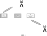
- FIG. 3 is a first schematic diagram of a configuration mode of a configured grant according to an embodiment of this application.
- a network side configures two SRS resource sets for UE.
- SRS resources indicated by srs-ResourceIndicator of the CG configuration or by an SRI field in DCI for activation belong to a first SRS resource set.
- a corresponding beam points to TRP1, and a power parameter of the CG configuration matches a target receiving TRP, namely TRP1, including a target receive power P0, a path loss reference signal PL-RS for calculating path loss, and a closed-loop power control adjustment state 1.
- the network side uses DCI to dynamically schedule retransmission of the data.
- the SRS resource indicated by the SRI field in the DCI belongs to a second SRS resource set, and the beam points to TRP2, meaning that the UE needs to use power control parameters that match a target TRP, namely TRP2, for transmitting the PUSCH retransmission.
- the UE can directly use SRI-PUSCH-powerControl that is mapped by an SRI value in the DCI for scheduling and that provides P0/ ⁇ , PL-RS, and closed-loop power control index.
- the UE may still use a power control reference signal of the CG configuration.
- PL-RS obtained for the PUSCH retransmission may indicate a large path loss, resulting in a large transmit power of the UE and causing interferences to other users. Therefore, the network may configure a negative power offset value for the CG and add this power offset value to a power calculated based on parameters of the CG. This ensures that the power for receiving the data by a base station is approximately equal to a power for data from other users to reach the base station.
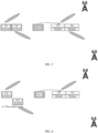
- FIG. 4 is a second schematic diagram of a configuration mode of a configured grant according to an embodiment of this application.
- one CG is configured with two srs-ResourceIndicators, or SRSs indicated by an SRI field in DCI for activation belong to two SRS resource sets, and two corresponding beams point to TRP1 and TRP2, respectively.
- Two sets of power control parameters are configured corresponding to the two SRIs.
- the network uses DCI to dynamically schedule retransmission of the data.
- SRS resources indicated by SRI in the DCI for scheduling belong to a same SRS resource set.
- UE when transmitting the PUSCH retransmission, UE uses power control parameters associated with a second SRI for power control. This is because the SRS resource set to which the SRS indicated by the SRI field in the DCI for dynamic scheduling belongs and the SRS resource set to which an SRS resource indicated by the second SRI in the CG belongs are the same resource set.
- the power control parameters of the CG can still be used, which ensures the performance for transmitting the data on the CG to the TRP.
- FIG. 5 is a third schematic diagram of a configuration mode of a configured grant according to an embodiment of this application.
- one CG is configured with two SRIs
- SRSs indicated by the SRIs belong to two SRS resource sets, and two corresponding beams point to TRP1 and TRP2, respectively.
- Two sets of power control parameters are configured corresponding to the two SRIs.
- the network uses DCI to dynamically schedule retransmission of the data.
- SRS resources indicated by SRI in the DCI for scheduling belong to two SRS resource sets.
- the UE uses the corresponding two sets of power control parameters of the CG for transmitting the PUSCH retransmission.
- FIG. 6 is a fourth schematic diagram of a configuration mode of a configured grant according to an embodiment of this application.
- one CG is configured with one srs-ResourceIndicator, and SRS resources indicated by the srs-ResourceIndicator belong to different SRS resource sets.
- Initial transmission of data is performed using two CGs, and two beams corresponding to the two CGs point to TRP1 and TRP2, respectively.
- the network uses DCI to dynamically schedule retransmission of the data.
- SRS resources indicated by SRI in the DCI for scheduling belong to a same SRS resource set.
- the UE when transmitting the PUSCH retransmission, uses power control parameters of CG1 for power control. This is because the SRS resource set to which the SRS indicated by the SRI field in the DCI for dynamic scheduling belongs and the SRS resource set to which an SRS resource indicated by the SRI in the CG1 belongs are the same resource set.
- FIG. 7 is a fifth schematic diagram of a configuration mode of a configured grant according to an embodiment of this application.
- one CG is configured with one srs-ResourceIndicator
- initial transmission of data is performed using two CGs
- SRS resources indicated by the srs-ResourceIndicators of the two CGs belong to different SRS resource sets, and two corresponding beams point to TRP1 and TRP2, respectively.
- the network uses DCI to dynamically schedule retransmission of the data, where SRS resources indicated by SRI in the DCI for scheduling belong to a same SRS resource set.
- a beam corresponding to a first transmission occasion indicates that an SRS resource indicated by the SRI belongs to a same SRS resource set as an SRS resource indicated by SRI of CG1, and power control parameters of the CG1 configuration are used at the first transmission occasion; and a beam corresponding to a second transmission occasion indicates that an SRS resource indicated by the SRI belongs to a same SRS resource set as an SRS resource indicated by SRI of CG2, and power control parameters of the CG2 configuration are used at the second transmission occasion.
- FIG. 8 is a sixth schematic diagram of a configuration mode of a configured grant according to an embodiment of this application.
- one CG is configured with one srs-ResourceIndicator
- initial transmission of data is performed using two CGs
- SRS resources indicated by the srs-ResourceIndicators of the two CGs belong to different SRS resource sets, and two corresponding beams point to TRP1 and TRP2, respectively.
- the two CGs are associated with different CORESETPoolIndex.
- the network uses two DCIs from CORESETs associated with different CORESETPoolIndex to dynamically schedule retransmission of the data, where SRS resources indicated by SRIs in the DCIs for scheduling belong to different SRS resource sets.
- the UE uses the power control parameters of the CG configuration for transmitting the PUSCH retransmission.
- CG2 configuration is used for PUSCH2.
- the power control parameters herein include P0/ ⁇ , PL-RS, and closed-loop power control state index 1.
- multiple sets of parameters are indicated/changed for a CG, thereby improving the reliability of CG transmission and ensuring that power for data retransmission on the CG matches a target TRP.
- FIG. 9a is a first schematic diagram of an apparatus for processing configured grant configuration according to an embodiment of this application. As shown in FIG. 9a , an embodiment of this application provides an apparatus for processing configured grant configuration, where the apparatus includes a receiving module 901.
- the receiving module 901 is configured to receive at least one configured grant CG configuration, where the CG configuration includes at least one parameter set, the parameter set includes one or more sounding reference signal resource indicators SRIs, and the SRI is used for indicating one or more sounding reference signal SRS resources.
- FIG. 9b is a second schematic diagram of an apparatus for processing configured grant configuration according to an embodiment of this application.
- an embodiment of this application provides an apparatus for processing configured grant configuration, where the apparatus includes a receiving module 901 and a transmitting module 902.
- the receiving module 901 is configured to receive at least one configured grant CG configuration, where the CG configuration includes at least one parameter set, the parameter set includes one or more sounding reference signal resource indicators SRIs, and the SRI is used for indicating one or more sounding reference signal SRS resources.
- the transmitting module 902 is configured to transmit an uplink message to a network-side device.
- the CG configuration is associated with an SRS resource set index
- the SRI in the at least one parameter set indicates an SRS resource in an SRS resource set identified by the corresponding associated SRS resource set index.
- the CG configuration is associated with a control resource set pool index CORESETPoolIndex; an SRS resource set is associated with a CORESETPoolIndex; and the SRI in the at least one parameter set indicates an SRS resource in a corresponding SRS resource set associated with the same CORESETPoolIndex.
- the at least one parameter set further includes one or more transmitted precoding matrix indicators TPMIs.
- the at least one parameter set includes multiple TPMI fields for indicating multiple TPMIs.
- the at least one parameter set includes one TPMI field, and the one TPMI field correspondingly indicates multiple TPMIs.
- a TPMI field in the at least one parameter set corresponds to an SRI field
- the apparatus further includes an updating module.
- the updating module is configured to update the parameter set included in the CG configuration by using at least one of the following:
- parameter sets corresponding to one or more CG configurations are simultaneously updated using one DCI, where the DCI includes multiple SRIs for indicating spatial relations and/or multiple TPMIs.
- the DCI satisfies at least one of the following conditions:
- a hybrid automatic repeat request HARQ process number field in the DCI corresponds to a CG index.
- a HARQ process number field in the DCI corresponds to one or more CG indexes.
- a code point of a HARQ process number field in the DCI is associated with at least one CG index; and a correspondence between information of the CG index associated with the code point and the code point of the HARQ process number field is pre-configured or configured by a network.
- the updated transmission parameter includes at least one of the following:
- multiple SRS resources indicated by the SRI field in the DCI are included in different SRS resource sets, and the SRS resources in each SRS resource set are used for updating SRIs in one parameter set.
- an SRS resource in a first SRS resource set is used for correspondingly updating an SRS resource indicated by a first SRI in a first CG configuration
- an SRS resource in a second SRS resource set is used for correspondingly updating an SRS resource indicated by a second SRI in a second CG configuration.
- multiple CG configurations indicated by a HARQ process number field are correspondingly updated using the SRI field in the DCI.
- At least one power control parameter set SRI-PUSCH-powerControl mapped by the SRI field in the DCI format includes P0/ ⁇ , PL-RS, and closed-loop power control index for correspondingly updating power control parameters of the CG.
- the MAC CE format includes one or more of the following parameters:
- a CG index corresponds to the parameter included in the MAC CE format
- One set of parameters includes one or more of the following parameters:
- a spatial relation of the SRS resources indicated by the SRI field of the CG is updated using higher-layer signaling; and a spatial relation used by the CG is the updated spatial relation of the SRS resources indicated by the SRI field of the CG.
- a path loss reference signal index corresponding to the SRS resource is used as a path loss reference signal index of the CG.
- the apparatus further includes a retransmitting module.
- the retransmitting module is configured to schedule a CG for data retransmission.
- a power control parameter corresponding to a PUSCH retransmission of CG scheduled by DCI is determined based on one or more power control parameters in the parameter set.
- the power control parameter includes one or more of the following: P0 / ⁇ ;
- a type-1 CG configuration includes the following parameters:
- a type-2 CG configuration includes the following parameters:
- the parameter set includes at least one power offset value, and the power offset value is associated with an SRS resource set.
- parameters in the CG configuration are used as the power control parameters of the PUSCH retransmission of CG scheduled by DCI.
- the power control parameters of the PUSCH retransmission of CG scheduled by DCI are associated with one or more P0/ ⁇ , powerControlLoopToUse, and path loss reference index pathlossReferenceIndex parameters of one or more SRS resource sets, where the SRS resource set is the same as an SRS resource set to which an SRS resource indicated by an SRI field in the DCI for dynamically scheduling the PUSCH retransmission belongs.
- one of the multiple sets of power control parameters of the PUSCH retransmission comes from the CG configuration, and the remaining sets of power control parameters are other power control parameters indicated by the SRI field in the DCI.
- power for the PUSCH retransmission of CG scheduled by DCI is obtained by adding a power offset value to a power calculated based on the parameters in the CG configuration.
- power control parameters of one or more CGs are used as the power control parameters of the PUSCH retransmission of CG scheduled by DCI.
- the power control parameters of the PUSCH retransmission of CG are indicated by the SRI field in the DCI for scheduling the PUSCH retransmission.
- higher-layer signaling indicates to a terminal whether the parameters in the CG configuration or the parameters indicated by DCI are used as the power control parameters of the PUSCH retransmission of CG.
- the higher-layer signaling is RRC or MAC CE.
- the power control parameters indicated by the DCI are used.
- the apparatus for processing configured grant configuration provided in this embodiment of this application can implement all method steps implemented in the foregoing embodiments of the method executed by a terminal, with the same technical effects achieved.
- the content and beneficial effects in this embodiment that are the same as those in the method embodiments are not described herein again.
- the apparatus for processing configured grant configuration in this embodiment of this application may be an apparatus, or may be a component, an integrated circuit, or a chip in a terminal.
- the apparatus may be a mobile terminal or a non-mobile terminal.
- the mobile terminal may include but is not limited to the types of the terminal 11 listed above, and the non-mobile terminal may be a server, a network attached storage (Network Attached Storage, NAS), a personal computer (personal computer, PC), a television (Television, TV), a teller machine, a self-service machine, and the like, which is not specifically limited in this embodiment of this application.
- Network Attached Storage Network Attached Storage
- PC personal computer
- TV television
- teller machine teller machine
- self-service machine a self-service machine
- the apparatus for processing configured grant configuration in this embodiment of this application may be an apparatus having an operating system.
- the operating system may be an Android (Android) operating system, iOS operating system, or another possible operating system. This is not specifically limited in the embodiments of this application.
- FIG. 10 is a schematic diagram of a hardware structure of a terminal according to an embodiment of this application.
- the terminal 1000 includes but is not limited to components such as a radio frequency unit 1001, a network module 1002, an audio output unit 1003, an input unit 1004, a sensor 1005, a display unit 1006, a user input unit 1007, an interface unit 1008, a memory 1009, and a processor 1010.
- the terminal 1000 may further include a power supply (for example, a battery) supplying power to the components.
- the power supply may be logically connected to the processor 1010 via a power management system, so that functions such as charge management, discharge management, and power consumption management are implemented by using the power management system.
- the structure of the terminal shown in FIG. 10 does not constitute any limitation on the terminal, and the terminal may include more or fewer components than shown in the figure, or a combination of some components, or components arranged differently. Details are not described herein.
- the input unit 1004 may include a graphics processing unit (Graphics Processing Unit, GPU) 10041 and a microphone 10042.
- the graphics processing unit 10041 processes image data of a static picture or a video that is obtained by an image capture apparatus (for example, a camera) in an image capture mode or a video capture mode.
- the display unit 1006 may include a display panel 10061.
- the display panel 10061 may be configured in a form of a liquid crystal display, an organic light-emitting diode display, or the like.
- the user input unit 1007 includes a touch panel 10071 and other input devices 10072.
- the touch panel 10071 is also referred to as a touchscreen.
- the touch panel 10071 may include two parts: a touch detection apparatus and a touch controller.
- the other input devices 10072 may include but are not limited to a physical keyboard, a function button (such as a volume control button or a power on/off button), a trackball, a mouse, a joystick, and the like. Details are not described herein.
- the radio frequency unit 1001 transmits downlink data received from a network-side device to the processor 1010 for processing, and in addition, transmits uplink data to the network-side device.
- the radio frequency unit 1001 includes but is not limited to an antenna, at least one amplifier, a transceiver, a coupler, a low noise amplifier, a duplexer, and the like.
- the memory 1009 may be configured to store software programs or instructions and various data.
- the memory 1009 may include a program or instruction storage area and a data storage area.
- the program or instruction storage area may store an operating system, an application program or instruction required by at least one function (for example, a sound playback function or an image playback function), and the like.
- the memory 1009 may include a high-speed random access memory, and may further include a non-volatile memory.
- the non-volatile memory may be a read-only memory (Read-Only Memory, ROM), a programmable read-only memory (Programmable ROM, PROM), an erasable programmable read-only memory (Erasable PROM, EPROM), an electrically erasable programmable read-only memory (Electrically EPROM, EEPROM), or a flash memory, for example, at least one disk storage device, flash memory device, or another non-volatile solid-state storage device.
- ROM Read-Only Memory
- PROM programmable read-only memory
- Erasable PROM Erasable PROM
- EPROM electrically erasable programmable read-only memory
- EEPROM electrically erasable programmable read-only memory
- flash memory for example, at least one disk storage device, flash memory device, or another non-volatile solid-state storage device.
- the processor 1010 may include one or more processing units.
- an application processor and a modem processor may be integrated in the processor 1010.
- the application processor mainly processes an operating system, a user interface, application programs or instructions, and the like.
- the modem processor mainly processes wireless communications, for example, being a baseband processor. It can be understood that the modem processor may alternatively be not integrated in the processor 1010.
- the radio frequency unit 1001 is configured to receive at least one configured grant CG configuration, where the CG configuration includes at least one parameter set, the parameter set includes one or more sounding reference signal resource indicators SRIs, and the SRI is used for indicating one or more sounding reference signal SRS resources.
- the CG configuration is associated with an SRS resource set index
- the SRI in the at least one parameter set indicates an SRS resource in an SRS resource set identified by the corresponding associated SRS resource set index.
- the CG configuration is associated with a control resource set pool index CORESETPoolIndex; an SRS resource set is associated with a CORESETPoolIndex; and the SRI in the at least one parameter set indicates an SRS resource in a corresponding SRS resource set associated with the same CORESETPoolIndex.
- the at least one parameter set further includes one or more transmitted precoding matrix indicators TPMIs.
- the at least one parameter set includes multiple TPMI fields for indicating multiple TPMIs.
- the at least one parameter set includes one TPMI field, and the one TPMI field correspondingly indicates multiple TPMIs.
- a TPMI field in the at least one parameter set corresponds to an SRI field
- the method further includes: updating the parameter set included in the CG configuration by using at least one of the following:
- parameter sets corresponding to one or more CG configurations are simultaneously updated using one DCI, where the DCI includes multiple SRIs for indicating spatial relations and/or multiple TPMIs.
- the DCI satisfies at least one of the following conditions:
- a hybrid automatic repeat request HARQ process number field in the DCI corresponds to a CG index.
- a HARQ process number field in the DCI corresponds to one or more CG indexes.
- a code point of a HARQ process number field in the DCI is associated with at least one CG index; and a correspondence between information of the CG index associated with the code point and the code point of the HARQ process number field is pre-configured or configured by a network.
- the updated transmission parameter includes at least one of the following:
- multiple SRS resources indicated by the SRI field in the DCI are included in different SRS resource sets, and the SRS resources in each SRS resource set are used for updating SRIs in one parameter set.
- an SRS resource in a first SRS resource set is used for correspondingly updating an SRS resource indicated by a first SRI in a first CG configuration
- an SRS resource in a second SRS resource set is used for correspondingly updating an SRS resource indicated by a second SRI in a second CG configuration.
- multiple CG configurations indicated by a HARQ process number field are correspondingly updated using the SRI field in the DCI.
- At least one power control parameter set SRI-PUSCH-powerControl mapped by the SRI field in the DCI format includes P0/ ⁇ , PL-RS, and closed-loop power control index for correspondingly updating power control parameters of the CG.
- the MAC CE format includes one or more of the following parameters:
- a CG index corresponds to the parameter included in the MAC CE format
- One set of parameters includes one or more of the following parameters:
- a spatial relation of the SRS resources indicated by the SRI field of the CG is updated using higher-layer signaling; and a spatial relation used by the CG is the updated spatial relation of the SRS resources indicated by the SRI field of the CG.
- a path loss reference signal index corresponding to the SRS resource is used as a path loss reference signal index of the CG.
- the method further includes: determining, based on one or more power control parameters in the parameter set, a power control parameter corresponding to a PUSCH retransmission of CG scheduled by DCI.
- the power control parameter includes one or more of the following: P0 / ⁇ ;
- a type-1 CG configuration includes the following parameters:
- a type-2 CG configuration includes the following parameters:
- the parameter set includes at least one power offset value, and the power offset value is associated with an SRS resource set.
- parameters in the CG configuration are used as the power control parameters of the PUSCH retransmission of CG scheduled by DCI.
- the power control parameters of the PUSCH retransmission of CG scheduled by DCI are associated with one or more P0/ ⁇ , powerControlLoopToUse, and path loss reference index pathlossReferenceIndex parameters of one or more SRS resource sets, where the SRS resource set is the same as an SRS resource set to which an SRS resource indicated by an SRI field in the DCI for dynamically scheduling the PUSCH retransmission belongs.
- one of the multiple sets of power control parameters of the PUSCH retransmission comes from the CG configuration, and the remaining sets of power control parameters are other power control parameters indicated by the SRI field in the DCI.
- power for the PUSCH retransmission of CG scheduled by DCI is obtained by adding a power offset value to a power calculated based on the parameters in the CG configuration.
- power control parameters of one or more CGs are used as the power control parameters of the PUSCH retransmission of CG scheduled by DCI.
- the power control parameters of the PUSCH retransmission of CG are indicated by the SRI field in the DCI for scheduling the PUSCH retransmission.
- higher-layer signaling indicates to a terminal whether the parameters in the CG configuration or the parameters indicated by DCI are used as the power control parameters of the PUSCH retransmission of CG.
- the higher-layer signaling is RRC or MAC CE.
- the power control parameters indicated by the DCI are used.
- the terminal provided in this embodiment of this application can implement all method steps implemented in the foregoing method embodiments, with the same technical effects achieved.
- the content and beneficial effects in this embodiment that are the same as those in the method embodiments are not specifically described herein again.
- An embodiment of this application further provides a readable storage medium, where the readable storage medium stores a program or instructions, and when the program or instructions are executed by a processor, the processes of the method for processing configured grant configuration in the foregoing embodiments are implemented, with the same technical effects achieved. To avoid repetition, details are not described herein again.
- the processor is a processor in the terminal described in the foregoing embodiment.
- the readable storage medium includes a computer-readable storage medium, for example, a computer read-only memory (Read-Only Memory, ROM), a random access memory (Random Access Memory, RAM), a magnetic disk, or an optical disc.
- an embodiment of this application provides a chip.
- the chip includes a processor and a communications interface.
- the communications interface is coupled to the processor.
- the processor is configured to run a program or instructions to implement the processes of the method for processing configured grant configuration in the foregoing embodiments, with the same technical effect achieved. To avoid repetition, details are not described herein again.
- the chip mentioned in this embodiment of this application may also be referred to as a system-level chip, a system chip, a chip system, a system-on-chip, or the like.
- the method in the foregoing embodiments may be implemented by software in combination with a necessary general hardware platform.
- the method may alternatively be implemented by hardware.
- the former is a preferred implementation.
- the technical solutions of this application essentially, or the part contributing to the prior art may be implemented in a form of a software product.
- the computer software product is stored in a storage medium (for example, a ROM/RAM, a magnetic disk, or an optical disc), and includes several instructions for instructing a terminal (which may be a mobile phone, a computer, a server, a network device, or the like) to perform the method described in the embodiments of this application.
Landscapes
- Engineering & Computer Science (AREA)
- Signal Processing (AREA)
- Computer Networks & Wireless Communication (AREA)
- Physics & Mathematics (AREA)
- Mathematical Physics (AREA)
- Mobile Radio Communication Systems (AREA)
Applications Claiming Priority (2)
| Application Number | Priority Date | Filing Date | Title |
|---|---|---|---|
| CN202110056385.3A CN114765873B (zh) | 2021-01-15 | 2021-01-15 | 配置授权的配置的处理方法、装置、设备及存储介质 |
| PCT/CN2022/072136 WO2022152269A1 (zh) | 2021-01-15 | 2022-01-14 | 配置授权的配置的处理方法、装置、设备及存储介质 |
Publications (2)
| Publication Number | Publication Date |
|---|---|
| EP4280757A1 true EP4280757A1 (de) | 2023-11-22 |
| EP4280757A4 EP4280757A4 (de) | 2024-06-26 |
Family
ID=82364019
Family Applications (1)
| Application Number | Title | Priority Date | Filing Date |
|---|---|---|---|
| EP22739144.8A Pending EP4280757A4 (de) | 2021-01-15 | 2022-01-14 | Konfigurationverarbeitungsverfahren und -vorrichtung für konfigurierte berechtigung, vorrichtung und speichermedium |
Country Status (6)
| Country | Link |
|---|---|
| US (1) | US20230354325A1 (de) |
| EP (1) | EP4280757A4 (de) |
| JP (1) | JP7604665B2 (de) |
| KR (1) | KR20230118678A (de) |
| CN (1) | CN114765873B (de) |
| WO (1) | WO2022152269A1 (de) |
Cited By (2)
| Publication number | Priority date | Publication date | Assignee | Title |
|---|---|---|---|---|
| EP4319011A4 (de) * | 2021-04-02 | 2024-06-05 | Fujitsu Limited | Verfahren, vorrichtung und system zur uplink-datenübertragung |
| EP4381821A1 (de) | 2021-08-05 | 2024-06-12 | Lenovo (Beijing) Limited | Verfahren und vorrichtungen für m-trp-basierte pusch-übertragung |
Families Citing this family (7)
| Publication number | Priority date | Publication date | Assignee | Title |
|---|---|---|---|---|
| US20230041585A1 (en) * | 2021-08-03 | 2023-02-09 | Qualcomm Incorporated | Power control parameter configuration for configured grants |
| WO2024148559A1 (zh) * | 2023-01-12 | 2024-07-18 | Oppo广东移动通信有限公司 | 无线通信的方法、终端设备和网络设备 |
| WO2024229785A1 (en) * | 2023-05-11 | 2024-11-14 | Qualcomm Incorporated | Path loss reference signal (plrs) identifier update for a configured grant (cg) |
| CN119183201A (zh) * | 2023-06-21 | 2024-12-24 | 华为技术有限公司 | 通信方法和通信装置 |
| EP4712654A1 (de) | 2023-07-18 | 2026-03-18 | Shenzhen Transsion Holdings Co., Ltd. | Verarbeitungsverfahren, kommunikationsvorrichtung und speichermedium |
| CN116600402B (zh) * | 2023-07-18 | 2024-01-19 | 深圳传音控股股份有限公司 | 处理方法、通信设备及存储介质 |
| WO2025059966A1 (zh) * | 2023-09-21 | 2025-03-27 | 华为技术有限公司 | 一种免动态授权传输配置的配置方法及相关装置 |
Family Cites Families (12)
| Publication number | Priority date | Publication date | Assignee | Title |
|---|---|---|---|---|
| US11729782B2 (en) * | 2018-06-11 | 2023-08-15 | Apple Inc. | Enhanced uplink beam management |
| JP7199184B2 (ja) * | 2018-09-11 | 2023-01-05 | シャープ株式会社 | 通信システムおよび通信装置 |
| US20220078828A1 (en) * | 2019-01-09 | 2022-03-10 | Ntt Docomo, Inc. | User terminal and radio communication method |
| KR102783574B1 (ko) * | 2019-02-01 | 2025-03-19 | 한국전자통신연구원 | 통신 시스템에서 그랜트 프리 방식에 기초한 상향링크 통신을 위한 방법 및 장치 |
| CN110536394B (zh) * | 2019-03-29 | 2024-04-05 | 中兴通讯股份有限公司 | 功率控制方法、装置和系统 |
| WO2020222295A1 (en) * | 2019-05-02 | 2020-11-05 | Sharp Kabushiki Kaisha | User equipment, base stations and signaling for multiple active configured grants |
| CN114303426B (zh) * | 2019-06-13 | 2024-10-15 | 欧芬诺有限责任公司 | 用于多服务的功率控制 |
| WO2020259063A1 (en) * | 2019-06-25 | 2020-12-30 | Telefonaktiebolaget Lm Ericsson (Publ) | Method and apparatus for supporting transmission adaptation |
| CN110536399B (zh) * | 2019-09-03 | 2024-10-15 | 中兴通讯股份有限公司 | 功率控制方法、装置和系统 |
| WO2021146161A1 (en) * | 2020-01-14 | 2021-07-22 | Ofinno, Llc | Pathloss based power control for configured uplink grant |
| CN115668852B (zh) * | 2020-04-17 | 2026-04-14 | 瑞典爱立信有限公司 | 用于到多个传输和接收点(trp)的同时传输的方法和装置 |
| WO2022024298A1 (ja) * | 2020-07-30 | 2022-02-03 | 株式会社Nttドコモ | 端末、無線通信方法及び基地局 |
-
2021
- 2021-01-15 CN CN202110056385.3A patent/CN114765873B/zh active Active
-
2022
- 2022-01-14 EP EP22739144.8A patent/EP4280757A4/de active Pending
- 2022-01-14 KR KR1020237024316A patent/KR20230118678A/ko active Pending
- 2022-01-14 WO PCT/CN2022/072136 patent/WO2022152269A1/zh not_active Ceased
- 2022-01-14 JP JP2023541333A patent/JP7604665B2/ja active Active
-
2023
- 2023-07-06 US US18/347,890 patent/US20230354325A1/en active Pending
Cited By (3)
| Publication number | Priority date | Publication date | Assignee | Title |
|---|---|---|---|---|
| EP4319011A4 (de) * | 2021-04-02 | 2024-06-05 | Fujitsu Limited | Verfahren, vorrichtung und system zur uplink-datenübertragung |
| EP4381821A1 (de) | 2021-08-05 | 2024-06-12 | Lenovo (Beijing) Limited | Verfahren und vorrichtungen für m-trp-basierte pusch-übertragung |
| EP4381821A4 (de) * | 2021-08-05 | 2025-04-23 | Lenovo (Beijing) Limited | Verfahren und vorrichtungen für m-trp-basierte pusch-übertragung |
Also Published As
| Publication number | Publication date |
|---|---|
| JP2024502148A (ja) | 2024-01-17 |
| US20230354325A1 (en) | 2023-11-02 |
| CN114765873A (zh) | 2022-07-19 |
| CN114765873B (zh) | 2026-01-02 |
| EP4280757A4 (de) | 2024-06-26 |
| KR20230118678A (ko) | 2023-08-11 |
| WO2022152269A1 (zh) | 2022-07-21 |
| JP7604665B2 (ja) | 2024-12-23 |
Similar Documents
| Publication | Publication Date | Title |
|---|---|---|
| EP4280757A1 (de) | Konfigurationverarbeitungsverfahren und -vorrichtung für konfigurierte berechtigung, vorrichtung und speichermedium | |
| US11540227B2 (en) | Power control configuration for uplink transmissions | |
| US11483777B2 (en) | Power headroom report generation | |
| EP3101982A1 (de) | Basisstation, übertragungsverfahren, mobilstation und rückübertragungssteuerungsverfahren | |
| US12520306B2 (en) | Uplink channel transmission method and apparatus, and terminal | |
| US20230354404A1 (en) | Method and apparatus for determining number of coded modulation symbols, and communications device | |
| EP4307589B1 (de) | Verfahren und endgerät zur erzeugung eines halbstatischen harq-ack-codebuchs | |
| US20230362912A1 (en) | Channel information sending method, channel information receiving method, and related device | |
| US12113625B2 (en) | HARQ-ACK feedback method and apparatus | |
| EP4510744A1 (de) | Informationsempfangsverfahren und -vorrichtung, informationssendeverfahren und -vorrichtung und vorrichtung | |
| EP4266820A1 (de) | Verfahren und vorrichtung zur kommunikationsverarbeitung und kommunikationsvorrichtung | |
| US20240023108A1 (en) | Method and apparatus for determining pucch resource, and terminal | |
| US20230354208A1 (en) | Power control method and apparatus, and user equipment | |
| US20240080847A1 (en) | Information transmission method and apparatus, terminal, and storage medium | |
| EP4478818A1 (de) | Verfahren und vorrichtung zur bestimmung des uplink-tci-status, endgerät und netzwerkseitige vorrichtung | |
| US20240236871A1 (en) | Method and Apparatus for Controlling Power for PUCCH Transmission and Terminal | |
| US20240048294A1 (en) | Pdsch transmission method and apparatus, pdsch reception method and apparatus, and communication device | |
| CN115362738B (zh) | 用于传送uci的pusch的装置和方法 | |
| WO2024125458A1 (zh) | Dci处理方法、ue和网络侧设备 | |
| CN120018302A (zh) | Bwp确定方法、dci发送方法、装置终端及网络侧设备 | |
| CN119946869A (zh) | 发送、接收下行控制信息dci的方法、装置、终端及网络侧设备 |
Legal Events
| Date | Code | Title | Description |
|---|---|---|---|
| STAA | Information on the status of an ep patent application or granted ep patent |
Free format text: STATUS: THE INTERNATIONAL PUBLICATION HAS BEEN MADE |
|
| PUAI | Public reference made under article 153(3) epc to a published international application that has entered the european phase |
Free format text: ORIGINAL CODE: 0009012 |
|
| STAA | Information on the status of an ep patent application or granted ep patent |
Free format text: STATUS: REQUEST FOR EXAMINATION WAS MADE |
|
| 17P | Request for examination filed |
Effective date: 20230706 |
|
| AK | Designated contracting states |
Kind code of ref document: A1 Designated state(s): AL AT BE BG CH CY CZ DE DK EE ES FI FR GB GR HR HU IE IS IT LI LT LU LV MC MK MT NL NO PL PT RO RS SE SI SK SM TR |
|
| DAV | Request for validation of the european patent (deleted) | ||
| DAX | Request for extension of the european patent (deleted) | ||
| A4 | Supplementary search report drawn up and despatched |
Effective date: 20240524 |
|
| RIC1 | Information provided on ipc code assigned before grant |
Ipc: H04L 5/00 20060101ALN20240517BHEP Ipc: H04L 1/00 20060101ALN20240517BHEP Ipc: H04B 7/0456 20170101ALN20240517BHEP Ipc: H04L 1/1829 20230101ALI20240517BHEP Ipc: H04L 1/1812 20230101ALI20240517BHEP Ipc: H04W 52/24 20090101ALI20240517BHEP Ipc: H04W 52/12 20090101ALI20240517BHEP Ipc: H04W 52/10 20090101ALI20240517BHEP Ipc: H04W 72/04 20090101AFI20240517BHEP |