EP4292803A2 - Staubschutz, aufhängevorrichtung und verfahren zur herstellung eines staubschutzes - Google Patents
Staubschutz, aufhängevorrichtung und verfahren zur herstellung eines staubschutzes Download PDFInfo
- Publication number
- EP4292803A2 EP4292803A2 EP23207598.6A EP23207598A EP4292803A2 EP 4292803 A2 EP4292803 A2 EP 4292803A2 EP 23207598 A EP23207598 A EP 23207598A EP 4292803 A2 EP4292803 A2 EP 4292803A2
- Authority
- EP
- European Patent Office
- Prior art keywords
- mold
- dust cover
- recess
- flange portion
- wall surface
- Prior art date
- Legal status (The legal status is an assumption and is not a legal conclusion. Google has not performed a legal analysis and makes no representation as to the accuracy of the status listed.)
- Granted
Links
Images




Classifications
-
- F—MECHANICAL ENGINEERING; LIGHTING; HEATING; WEAPONS; BLASTING
- F16—ENGINEERING ELEMENTS AND UNITS; GENERAL MEASURES FOR PRODUCING AND MAINTAINING EFFECTIVE FUNCTIONING OF MACHINES OR INSTALLATIONS; THERMAL INSULATION IN GENERAL
- F16F—SPRINGS; SHOCK-ABSORBERS; MEANS FOR DAMPING VIBRATION
- F16F9/00—Springs, vibration-dampers, shock-absorbers, or similarly-constructed movement-dampers using a fluid or the equivalent as damping medium
- F16F9/32—Details
- F16F9/38—Covers for protection or appearance
-
- F—MECHANICAL ENGINEERING; LIGHTING; HEATING; WEAPONS; BLASTING
- F16—ENGINEERING ELEMENTS AND UNITS; GENERAL MEASURES FOR PRODUCING AND MAINTAINING EFFECTIVE FUNCTIONING OF MACHINES OR INSTALLATIONS; THERMAL INSULATION IN GENERAL
- F16J—PISTONS; CYLINDERS; SEALINGS
- F16J3/00—Diaphragms; Bellows; Bellows pistons
- F16J3/04—Bellows
- F16J3/041—Non-metallic bellows
- F16J3/042—Fastening details
-
- B—PERFORMING OPERATIONS; TRANSPORTING
- B29—WORKING OF PLASTICS; WORKING OF SUBSTANCES IN A PLASTIC STATE IN GENERAL
- B29C—SHAPING OR JOINING OF PLASTICS; SHAPING OF MATERIAL IN A PLASTIC STATE, NOT OTHERWISE PROVIDED FOR; AFTER-TREATMENT OF THE SHAPED PRODUCTS, e.g. REPAIRING
- B29C49/00—Blow-moulding, i.e. blowing a preform or parison to a desired shape within a mould; Apparatus therefor
- B29C49/02—Combined blow-moulding and manufacture of the preform or the parison
- B29C49/04—Extrusion blow-moulding
-
- B—PERFORMING OPERATIONS; TRANSPORTING
- B29—WORKING OF PLASTICS; WORKING OF SUBSTANCES IN A PLASTIC STATE IN GENERAL
- B29C—SHAPING OR JOINING OF PLASTICS; SHAPING OF MATERIAL IN A PLASTIC STATE, NOT OTHERWISE PROVIDED FOR; AFTER-TREATMENT OF THE SHAPED PRODUCTS, e.g. REPAIRING
- B29C49/00—Blow-moulding, i.e. blowing a preform or parison to a desired shape within a mould; Apparatus therefor
- B29C49/42—Component parts, details or accessories; Auxiliary operations
- B29C49/48—Moulds
- B29C49/4802—Moulds with means for locally compressing part(s) of the parison in the main blowing cavity
- B29C49/4812—Moulds with means for locally compressing part(s) of the parison in the main blowing cavity and welding opposite wall parts of the parisons or preforms to each other
- B29C49/4815—Moulds with means for locally compressing part(s) of the parison in the main blowing cavity and welding opposite wall parts of the parisons or preforms to each other by means of movable mould parts
-
- B—PERFORMING OPERATIONS; TRANSPORTING
- B60—VEHICLES IN GENERAL
- B60G—VEHICLE SUSPENSION ARRANGEMENTS
- B60G15/00—Resilient suspensions characterised by arrangement, location or type of combined spring and vibration damper, e.g. telescopic type
- B60G15/02—Resilient suspensions characterised by arrangement, location or type of combined spring and vibration damper, e.g. telescopic type having mechanical spring
- B60G15/06—Resilient suspensions characterised by arrangement, location or type of combined spring and vibration damper, e.g. telescopic type having mechanical spring and fluid damper
- B60G15/062—Resilient suspensions characterised by arrangement, location or type of combined spring and vibration damper, e.g. telescopic type having mechanical spring and fluid damper the spring being arranged around the damper
-
- B—PERFORMING OPERATIONS; TRANSPORTING
- B60—VEHICLES IN GENERAL
- B60G—VEHICLE SUSPENSION ARRANGEMENTS
- B60G15/00—Resilient suspensions characterised by arrangement, location or type of combined spring and vibration damper, e.g. telescopic type
- B60G15/02—Resilient suspensions characterised by arrangement, location or type of combined spring and vibration damper, e.g. telescopic type having mechanical spring
- B60G15/06—Resilient suspensions characterised by arrangement, location or type of combined spring and vibration damper, e.g. telescopic type having mechanical spring and fluid damper
- B60G15/067—Resilient suspensions characterised by arrangement, location or type of combined spring and vibration damper, e.g. telescopic type having mechanical spring and fluid damper characterised by the mounting on the vehicle body or chassis of the spring and damper unit
-
- F—MECHANICAL ENGINEERING; LIGHTING; HEATING; WEAPONS; BLASTING
- F16—ENGINEERING ELEMENTS AND UNITS; GENERAL MEASURES FOR PRODUCING AND MAINTAINING EFFECTIVE FUNCTIONING OF MACHINES OR INSTALLATIONS; THERMAL INSULATION IN GENERAL
- F16J—PISTONS; CYLINDERS; SEALINGS
- F16J15/00—Sealings
- F16J15/50—Sealings between relatively-movable members, by means of a sealing without relatively-moving surfaces, e.g. fluid-tight sealings for transmitting motion through a wall
- F16J15/52—Sealings between relatively-movable members, by means of a sealing without relatively-moving surfaces, e.g. fluid-tight sealings for transmitting motion through a wall by means of sealing bellows or diaphragms
-
- B—PERFORMING OPERATIONS; TRANSPORTING
- B29—WORKING OF PLASTICS; WORKING OF SUBSTANCES IN A PLASTIC STATE IN GENERAL
- B29C—SHAPING OR JOINING OF PLASTICS; SHAPING OF MATERIAL IN A PLASTIC STATE, NOT OTHERWISE PROVIDED FOR; AFTER-TREATMENT OF THE SHAPED PRODUCTS, e.g. REPAIRING
- B29C49/00—Blow-moulding, i.e. blowing a preform or parison to a desired shape within a mould; Apparatus therefor
- B29C49/42—Component parts, details or accessories; Auxiliary operations
- B29C49/48—Moulds
- B29C2049/4879—Moulds characterised by mould configurations
- B29C2049/4892—Mould halves consisting of an independent main and bottom part
-
- B—PERFORMING OPERATIONS; TRANSPORTING
- B29—WORKING OF PLASTICS; WORKING OF SUBSTANCES IN A PLASTIC STATE IN GENERAL
- B29K—INDEXING SCHEME ASSOCIATED WITH SUBCLASSES B29B, B29C OR B29D, RELATING TO MOULDING MATERIALS OR TO MATERIALS FOR MOULDS, REINFORCEMENTS, FILLERS OR PREFORMED PARTS, e.g. INSERTS
- B29K2101/00—Use of unspecified macromolecular compounds as moulding material
- B29K2101/12—Thermoplastic materials
-
- B—PERFORMING OPERATIONS; TRANSPORTING
- B29—WORKING OF PLASTICS; WORKING OF SUBSTANCES IN A PLASTIC STATE IN GENERAL
- B29L—INDEXING SCHEME ASSOCIATED WITH SUBCLASS B29C, RELATING TO PARTICULAR ARTICLES
- B29L2022/00—Hollow articles
- B29L2022/02—Inflatable articles
- B29L2022/025—Bladders
-
- B—PERFORMING OPERATIONS; TRANSPORTING
- B29—WORKING OF PLASTICS; WORKING OF SUBSTANCES IN A PLASTIC STATE IN GENERAL
- B29L—INDEXING SCHEME ASSOCIATED WITH SUBCLASS B29C, RELATING TO PARTICULAR ARTICLES
- B29L2031/00—Other particular articles
- B29L2031/30—Vehicles, e.g. ships or aircraft, or body parts thereof
-
- B—PERFORMING OPERATIONS; TRANSPORTING
- B29—WORKING OF PLASTICS; WORKING OF SUBSTANCES IN A PLASTIC STATE IN GENERAL
- B29L—INDEXING SCHEME ASSOCIATED WITH SUBCLASS B29C, RELATING TO PARTICULAR ARTICLES
- B29L2031/00—Other particular articles
- B29L2031/755—Membranes, diaphragms
-
- B—PERFORMING OPERATIONS; TRANSPORTING
- B29—WORKING OF PLASTICS; WORKING OF SUBSTANCES IN A PLASTIC STATE IN GENERAL
- B29L—INDEXING SCHEME ASSOCIATED WITH SUBCLASS B29C, RELATING TO PARTICULAR ARTICLES
- B29L2031/00—Other particular articles
- B29L2031/774—Springs
-
- B—PERFORMING OPERATIONS; TRANSPORTING
- B60—VEHICLES IN GENERAL
- B60G—VEHICLE SUSPENSION ARRANGEMENTS
- B60G2202/00—Indexing codes relating to the type of spring, damper or actuator
- B60G2202/30—Spring/Damper and/or actuator Units
- B60G2202/31—Spring/Damper and/or actuator Units with the spring arranged around the damper, e.g. MacPherson strut
- B60G2202/312—The spring being a wound spring
-
- B—PERFORMING OPERATIONS; TRANSPORTING
- B60—VEHICLES IN GENERAL
- B60G—VEHICLE SUSPENSION ARRANGEMENTS
- B60G2204/00—Indexing codes related to suspensions per se or to auxiliary parts
- B60G2204/10—Mounting of suspension elements
- B60G2204/12—Mounting of springs or dampers
- B60G2204/124—Mounting of coil springs
- B60G2204/1242—Mounting of coil springs on a damper, e.g. MacPerson strut
-
- B—PERFORMING OPERATIONS; TRANSPORTING
- B60—VEHICLES IN GENERAL
- B60G—VEHICLE SUSPENSION ARRANGEMENTS
- B60G2204/00—Indexing codes related to suspensions per se or to auxiliary parts
- B60G2204/10—Mounting of suspension elements
- B60G2204/12—Mounting of springs or dampers
- B60G2204/128—Damper mount on vehicle body or chassis
-
- B—PERFORMING OPERATIONS; TRANSPORTING
- B60—VEHICLES IN GENERAL
- B60G—VEHICLE SUSPENSION ARRANGEMENTS
- B60G2204/00—Indexing codes related to suspensions per se or to auxiliary parts
- B60G2204/40—Auxiliary suspension parts; Adjustment of suspensions
-
- B—PERFORMING OPERATIONS; TRANSPORTING
- B60—VEHICLES IN GENERAL
- B60G—VEHICLE SUSPENSION ARRANGEMENTS
- B60G2204/00—Indexing codes related to suspensions per se or to auxiliary parts
- B60G2204/40—Auxiliary suspension parts; Adjustment of suspensions
- B60G2204/43—Fittings, brackets or knuckles
- B60G2204/4308—Protecting guards, e.g. for rigid axle damage protection
-
- B—PERFORMING OPERATIONS; TRANSPORTING
- B60—VEHICLES IN GENERAL
- B60G—VEHICLE SUSPENSION ARRANGEMENTS
- B60G2206/00—Indexing codes related to the manufacturing of suspensions: constructional features, the materials used, procedures or tools
- B60G2206/01—Constructional features of suspension elements, e.g. arms, dampers, springs
- B60G2206/012—Hollow or tubular elements
-
- B—PERFORMING OPERATIONS; TRANSPORTING
- B60—VEHICLES IN GENERAL
- B60G—VEHICLE SUSPENSION ARRANGEMENTS
- B60G2206/00—Indexing codes related to the manufacturing of suspensions: constructional features, the materials used, procedures or tools
- B60G2206/01—Constructional features of suspension elements, e.g. arms, dampers, springs
- B60G2206/40—Constructional features of dampers and/or springs
- B60G2206/42—Springs
- B60G2206/424—Plunger or top retainer construction for bellows or rolling lobe type air springs
-
- B—PERFORMING OPERATIONS; TRANSPORTING
- B60—VEHICLES IN GENERAL
- B60G—VEHICLE SUSPENSION ARRANGEMENTS
- B60G2206/00—Indexing codes related to the manufacturing of suspensions: constructional features, the materials used, procedures or tools
- B60G2206/01—Constructional features of suspension elements, e.g. arms, dampers, springs
- B60G2206/70—Materials used in suspensions
- B60G2206/71—Light weight materials
- B60G2206/7104—Thermoplastics
-
- B—PERFORMING OPERATIONS; TRANSPORTING
- B60—VEHICLES IN GENERAL
- B60G—VEHICLE SUSPENSION ARRANGEMENTS
- B60G2206/00—Indexing codes related to the manufacturing of suspensions: constructional features, the materials used, procedures or tools
- B60G2206/01—Constructional features of suspension elements, e.g. arms, dampers, springs
- B60G2206/70—Materials used in suspensions
- B60G2206/73—Rubber; Elastomers
-
- B—PERFORMING OPERATIONS; TRANSPORTING
- B60—VEHICLES IN GENERAL
- B60G—VEHICLE SUSPENSION ARRANGEMENTS
- B60G2206/00—Indexing codes related to the manufacturing of suspensions: constructional features, the materials used, procedures or tools
- B60G2206/01—Constructional features of suspension elements, e.g. arms, dampers, springs
- B60G2206/80—Manufacturing procedures
- B60G2206/81—Shaping
-
- B—PERFORMING OPERATIONS; TRANSPORTING
- B60—VEHICLES IN GENERAL
- B60G—VEHICLE SUSPENSION ARRANGEMENTS
- B60G2800/00—Indexing codes relating to the type of movement or to the condition of the vehicle and to the end result to be achieved by the control action
- B60G2800/16—Running
- B60G2800/162—Reducing road induced vibrations
-
- F—MECHANICAL ENGINEERING; LIGHTING; HEATING; WEAPONS; BLASTING
- F16—ENGINEERING ELEMENTS AND UNITS; GENERAL MEASURES FOR PRODUCING AND MAINTAINING EFFECTIVE FUNCTIONING OF MACHINES OR INSTALLATIONS; THERMAL INSULATION IN GENERAL
- F16F—SPRINGS; SHOCK-ABSORBERS; MEANS FOR DAMPING VIBRATION
- F16F2224/00—Materials; Material properties
- F16F2224/02—Materials; Material properties solids
-
- F—MECHANICAL ENGINEERING; LIGHTING; HEATING; WEAPONS; BLASTING
- F16—ENGINEERING ELEMENTS AND UNITS; GENERAL MEASURES FOR PRODUCING AND MAINTAINING EFFECTIVE FUNCTIONING OF MACHINES OR INSTALLATIONS; THERMAL INSULATION IN GENERAL
- F16F—SPRINGS; SHOCK-ABSORBERS; MEANS FOR DAMPING VIBRATION
- F16F2226/00—Manufacturing; Treatments
- F16F2226/04—Assembly or fixing methods; methods to form or fashion parts
Definitions
- the present invention relates to a dust cover that covers an outer side of a damper used in a vehicle, a suspension device including the dust cover, and a method for manufacturing the dust cover.
- the dust cover includes bellows portions and a flange portion that is formed at an end portion of the bellows portions and has a larger outer diameter than the bellows portions.
- the flange portion is interposed between a mount portion to which an upper end side of the damper is fixed and that is attached to a vehicle body side and a seat rubber that receives an upper end of the coil springs.
- the dust cover formed of a thermoplastic resin is manufactured by blow molding.
- air is fed into an inner side of the thermoplastic resin in a state where a molten tubular thermoplastic resin is disposed in a mold, and the thermoplastic resin is expanded in a radial direction and is deformed into a shape along an inner wall surface of the mold.
- a thickness of a portion of the thermoplastic resin having a large radial dimension is smaller than a thickness of the other portion. Accordingly, a thickness of a radially outer end of the bellows portions is smaller than a thickness of a radially inner end of the bellows portions, and the dust cover can expand and contract in an axial direction by deforming a radially outer end side of the bellows portions.
- Patent Literature 1 JP 2016-048 081 A
- the present invention has been made in view of the above circumstances, and an object of the present invention is to provide a dust cover, a suspension device including the dust cover, and a method of manufacturing the dust cover that uses a thermoplastic resin and ensures strength of a flange portion.
- the present invention provides a substantially cylindrical dust cover that is formed of a thermoplastic resin molded by blow molding and covers an outer side of a damper extending in a predetermined direction.
- the dust cover includes bellows portions that are formed in a predetermined section in an axial direction in the dust cover, that are inclined alternately toward a radially outer side and a radially inner side in the axial direction, that each has a radially outer end thinner than a radially inner end, and that can expand and contract in the axial direction, and a flange portion that is formed at a predetermined position in the axial direction of the dust cover and extends radially outward from a cylindrical portion of the dust cover.
- the flange portion protrudes radially outward from the cylindrical portion of the dust cover by a dimension larger than a height dimension in a radial direction between the radially inner end and the radially outer end of each of the bellows portions, and a thickness of the flange portion is larger than a thickness of the radially outer end of each of the bellows portions.
- the dust cover it is possible to ensure strength of the flange portion by making the thickness of the flange portion relatively large while ensuring an expansion and contraction function by making the thickness of the radially outer end of each of the bellows portions relatively small.
- the flange portion may be disposed at one end side of the dust cover in the axial direction.
- the one end side of the dust cover in the axial direction can be attached to another component by engaging the flange portion with the component.
- a cylindrical unnecessary portion is formed at an end portion in the axial direction during blow molding.
- a processing such as cutting out one end in the axial direction is extremely complicated and manufacturing costs increase.
- a processing on the one end in the axial direction is easy and costs can be reduced.
- the suspension device includes the dust cover that is disposed such that the axial direction is an up and down direction, a damper whose radially outer side is covered by the dust cover, a coil spring disposed at a radially outer side of the dust cover, a mount portion to which an upper end side of the damper is connected and that is attached to a vehicle body, and an upper seat that is disposed at a lower side of the mount portion and receives an upper end of the coil spring.
- the flange portion of the dust cover is interposed between the mount portion and the upper seat, and the mount portion includes a recessed portion that is formed on a lower surface of the mount portion and receives the protrusion of the dust cover.
- the suspension device it is possible to improve strength of the portion to be attached to the mount portion of the dust cover while reducing manufacturing costs of the dust cover.
- the method for manufacturing the dust cover includes a placement step of placing a molten thermoplastic resin having a tubular shape inside the mold in a state where an axial dimension of the recess of the inner wall surface is set to the primary molding distance, a primary molding step of blowing air into the thermoplastic resin placed inside the mold in the placement step to deform the thermoplastic resin along the inner wall surface of the mold, and a secondary molding step of compressing, in the axial direction, a portion of the thermoplastic resin that is molded in the primary molding step and enters the recess by changing the axial dimension of the recess of the inner wall surface to the final molding distance.
- the molten resin entering the recess having an axial dimension larger than the thickness of the flange portion in the primary molding step is compressed in the axial direction until the axial dimension of the recess reaches the thickness of the flange portion in the secondary molding step.
- the thickness of the flange portion can be made relatively large even in the case of blow molding the thermoplastic resin.
- a method for manufacturing a substantially cylindrical dust cover that covers an outer side of a damper extending in a predetermined direction and includes bellows portions that can expand and contract in an axial direction and a flange portion that extends radially outward.
- An inner wall surface of a mold used in blow molding has a recess corresponding to the flange portion, and the mold has a variable mechanism that changes an axial dimension of the recess to a final molding distance corresponding to a thickness of the flange portion and a primary molding distance larger than the final molding distance.
- the method for manufacturing the dust cover includes a placement step of placing a molten thermoplastic resin having a tubular shape inside the mold in a state where an axial dimension of the recess of the inner wall surface is set to the primary molding distance, a primary molding step of blowing air into the thermoplastic resin placed inside the mold in the placement step to deform the thermoplastic resin along the inner wall surface of the mold, and a secondary molding step of compressing, in the axial direction, a portion of the thermoplastic resin that is molded in the primary molding step and enters the recess by changing the axial dimension of the recess of the inner wall surface to the final molding distance.
- the mold includes a first mold corresponding to one side in an axial direction of the flange portion in the dust cover, and a second mold that is formed corresponding to the other side in the axial direction of the flange portion in the dust cover and can move relative to the first mold in the axial direction, and the recess of the inner wall surface may be formed by combining inner wall surfaces of the first mold and the second mold.
- the axial dimension of the recess is changed by a movement of the second mold relative to the first mold in the axial direction.
- FIG. 5 is a diagram showing a state in which air is fed into the molten resin in the mold
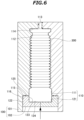
- FIG. 6 is a diagram showing a state in which the molten resin in a recess of an inner wall surface of the mold is compressed
- FIG. 7 is a diagram showing a state in which the mold is divided to take out a solidified and hollow resin molded product
- FIG. 8 is a diagram showing a state in which two ends in an axial direction of the hollow resin molded product are cut out.
- a suspension device 1 includes coil springs 2 that are disposed between a vehicle body 200 and a wheel (not shown) and elastically receive an up-down movement of a wheel relative to the vehicle body 200, and a damper 3 that is disposed inside the coil springs 2 and attenuates the up-down movement.
- the suspension device 1 includes a mount portion 4 to which an upper end side of the damper 3 is attached and that is fixed to the vehicle body 200, and a bracket 5 that is formed at a lower end side of the damper 3 and is coupled to a wheel side.
- the suspension device 1 further includes a dust cover 6 that is disposed inside the coil springs 2 and covers an outer side of the damper 3.
- the dust cover 6 is disposed such that an axial direction is an up and down direction.
- the lower end of the coil springs 2 is received by the lower seat 33, and an upper end of the coil springs 2 is received by an upper seat 42 that is formed of a rubber material and is disposed below the mount portion 4.
- a flange portion 63 of the dust cover 6 is interposed between the mount portion 4 and the upper seat 42.
- the dust cover 6 is formed of a thermoplastic resin and is manufactured by blow molding.
- thermoplastic resin used here includes not only a plastic having a relatively low hardness but also a thermoplastic elastomer that is flexible and exhibits rubber elasticity.
- the dust cover 6 is formed into a substantially cylindrical shape, and covers an outer side of the damper 3 from the upper seat 42 to the lower seat 33.
- the dust cover 6 includes bellows portions 61 formed in a predetermined section in the axial direction, an upper end side cylindrical portion 62 extending upward from an upper end of the bellows portions 61, the flange portion 63 extending radially outward from a predetermined portion in the axial direction of the upper end side cylindrical portion 62, a lower end side cylindrical portion 64 extending downward from a lower end of the bellows portions 61, and an expanded lower end portion 65 that is expanded downward from a lower end of the lower end side cylindrical portion 64.
- the bellows portions 61 are inclined alternately toward a radially inner side and a radially outer side in the up and down direction.
- a radially outer end of each of the bellows portions 61 is formed to be thinner than a radially inner end.
- the bellows portions 61 can expand and contract in the up and down direction.
- the flange portion 63 is disposed on an upper end side of the dust cover 6, and the upper end side of the dust cover 6 is attached to another component by engaging the flange portion 63 with the component.
- the flange portion 63 is formed to be separated from an upper end of the upper end side cylindrical portion 62.
- a protrusion 62b protruding upward from an upper surface of the flange portion 63 is formed at an upper side of the upper end side cylindrical portion 62 above the flange portion 63.
- the flange portion 63 protrudes radially outward by a dimension larger than a radial dimension between a valley portion 61a and a peak portion 61b of the bellows portion 61.
- a thickness of the flange portion 63 is formed to be larger than a thickness of the radially outer end of each of the bellows portions 61.
- a ratio of the thickness of the flange portion 63 to the thickness of the bellows portions 61 can be set freely.
- a thickness of a radially outer end of the flange portion 63 may be twice or more the thickness of the radially outer end of each of the bellows portions 61.
- the first mold 101 is disposed on an upper side, and the second mold 102 is disposed on a lower side.
- the variable mechanism changes the axial dimension of the recess 130 to a final molding distance corresponding to the thickness of the flange portion 63 and a primary molding distance larger than the final molding distance.
- the first mold 101 and the second mold 102 can be divided on a plane passing through a central axis.
- an inner wall surface 111 of the first mold 101 includes a main wall surface 112 having a shape corresponding to a lower side of the flange portion 63 of the dust cover 6, an introduction wall surface 113 formed corresponding to an air introduction port 310 of a molten resin 300 and extending in the up and down direction, a connection wall surface 114 connecting an upper end of the main wall surface 112 and a lower end of the introduction wall surface 113 and extending horizontally, a first flange wall surface 115 formed corresponding to the flange portion 63 of the dust cover 6 and extending from a lower end of the main wall surface 112 to left and right outer sides, and a vertical wall surface 116 extending downward from left and right outer ends of the first flange wall surface 115.
- the second mold 102 is disposed in a space defined by the vertical wall surface 116 of the first mold 101.
- An outer wall surface 122 of the second mold 102 extends in the up and down direction and is in contact with the vertical wall surface 116 of the first mold 101. Accordingly, the second mold 102 closes the other axial end (lower end) of the first mold 101, and is guided by the vertical wall surface 116 of the first mold 101 to move in the axial direction.
- the inner wall surface 121 of the second mold 102 includes a main wall surface 123 having a shape corresponding to an upper side of the flange portion 63 of the dust cover 6, a closing wall surface 124 that extends horizontally from a lower end of the main wall surface 123 and closes a lower end side of the molten resin 300, and a second flange wall surface 125 formed corresponding to the flange portion 63 of the dust cover 6 and extending from an upper end of the main wall surface 123 to left and right outer sides.
- the recess 130 is formed by the first flange wall surface 115 and the vertical wall surface 116 of the first mold 110 and the second flange wall surface 125 of the second mold 102, and an axial dimension of the recess 130 is changed by a movement of the second mold 102 in the axial direction.
- thermoplastic resin serving as a raw material is melted and extruded into a cylindrical shape using an extruder to obtain the tubular molten resin 300.
- the molten resin 300 is placed between the first mold 101 and second mold 102 obtained by dividing the mold 100 (preparation step).
- the first mold 101 and the second mold 102 are closed, and the molten resin 300 is placed inside the mold 100 (placement step).
- the recess 130 of the inner wall surface 110 has a primary molding distance larger than the thickness of the flange portion 63.
- the dust cover 6 is formed in an up and down inverted state.
- the first mold 100 and the second mold 120 are divided to take out a solidified and hollow resin molded product (mold releasing step).
- the hollow resin molded product is in a state where unnecessary portions are formed at two ends in the axial direction.
- the unnecessary portions of the hollow resin molded product are cut out, and manufacturing of the dust cover 6 is finished.
- the cylindrical unnecessary portions are formed at end portions of the dust cover 6 in the axial direction during blow molding.
- the protrusion 62b is formed on the flange portion 63 at an upper end of the dust cover 6 in the embodiment described above, it is needless to say that the flange portion 63 may be configured to form an end portion of the dust cover 6 in the axial direction. In this case, the recessed portion 44 of the mount portion 4 is unnecessary. A position in the axial direction where the flange portion 63 is formed can also be appropriately changed in the dust cover 6.
- the mold 100 includes the first mold 101 and the second mold 102 and an axial dimension of the recess 130 of the mold 100 is changed by moving the second mold 102 relative to the first mold 101 in the above embodiment, the dimension of the recess may be changed using other variable mechanisms.
Landscapes
- Engineering & Computer Science (AREA)
- General Engineering & Computer Science (AREA)
- Mechanical Engineering (AREA)
- Manufacturing & Machinery (AREA)
- Diaphragms And Bellows (AREA)
- Moulds For Moulding Plastics Or The Like (AREA)
- Blow-Moulding Or Thermoforming Of Plastics Or The Like (AREA)
- Vehicle Body Suspensions (AREA)
- Sealing Devices (AREA)
- Fluid-Damping Devices (AREA)
Applications Claiming Priority (3)
| Application Number | Priority Date | Filing Date | Title |
|---|---|---|---|
| JP2019060543A JP7223369B2 (ja) | 2019-03-27 | 2019-03-27 | ダストカバー、サスペンション装置及びダストカバーの製造方法 |
| PCT/JP2019/048307 WO2020194903A1 (ja) | 2019-03-27 | 2019-12-10 | ダストカバー、サスペンション装置及びダストカバーの製造方法 |
| EP19921675.5A EP3951215B1 (de) | 2019-03-27 | 2019-12-10 | Staubschutz, aufhängevorrichtung und verfahren zur herstellung eines staubschutzes |
Related Parent Applications (2)
| Application Number | Title | Priority Date | Filing Date |
|---|---|---|---|
| EP19921675.5A Division EP3951215B1 (de) | 2019-03-27 | 2019-12-10 | Staubschutz, aufhängevorrichtung und verfahren zur herstellung eines staubschutzes |
| EP19921675.5A Division-Into EP3951215B1 (de) | 2019-03-27 | 2019-12-10 | Staubschutz, aufhängevorrichtung und verfahren zur herstellung eines staubschutzes |
Publications (3)
| Publication Number | Publication Date |
|---|---|
| EP4292803A2 true EP4292803A2 (de) | 2023-12-20 |
| EP4292803A3 EP4292803A3 (de) | 2023-12-27 |
| EP4292803B1 EP4292803B1 (de) | 2025-12-03 |
Family
ID=72608757
Family Applications (2)
| Application Number | Title | Priority Date | Filing Date |
|---|---|---|---|
| EP23207598.6A Active EP4292803B1 (de) | 2019-03-27 | 2019-12-10 | Staubschutz, aufhängevorrichtung und verfahren zur herstellung eines staubschutzes |
| EP19921675.5A Active EP3951215B1 (de) | 2019-03-27 | 2019-12-10 | Staubschutz, aufhängevorrichtung und verfahren zur herstellung eines staubschutzes |
Family Applications After (1)
| Application Number | Title | Priority Date | Filing Date |
|---|---|---|---|
| EP19921675.5A Active EP3951215B1 (de) | 2019-03-27 | 2019-12-10 | Staubschutz, aufhängevorrichtung und verfahren zur herstellung eines staubschutzes |
Country Status (5)
| Country | Link |
|---|---|
| US (1) | US12140199B2 (de) |
| EP (2) | EP4292803B1 (de) |
| JP (1) | JP7223369B2 (de) |
| CN (1) | CN113614419B (de) |
| WO (1) | WO2020194903A1 (de) |
Families Citing this family (2)
| Publication number | Priority date | Publication date | Assignee | Title |
|---|---|---|---|---|
| SE546713C2 (en) * | 2022-12-22 | 2025-02-11 | Husqvarna Ab | Robotic lawnmower and bellows element |
| CN118493827B (zh) * | 2024-06-26 | 2024-11-15 | 广东功成实业有限公司 | 一种塑料制品可调式吹制设备 |
Citations (1)
| Publication number | Priority date | Publication date | Assignee | Title |
|---|---|---|---|---|
| JP2016048081A (ja) | 2014-08-27 | 2016-04-07 | 株式会社ショーワ | 懸架装置およびカバー部材 |
Family Cites Families (21)
| Publication number | Priority date | Publication date | Assignee | Title |
|---|---|---|---|---|
| JPS6035938U (ja) * | 1983-08-18 | 1985-03-12 | 株式会社 モルテン | サスペンションのストップラバ−構造 |
| JPS60199632A (ja) * | 1984-03-24 | 1985-10-09 | Meihou Kogyo Kk | 吹込成形法によるフランジ付管体の製造法 |
| JPS62165041A (ja) * | 1986-01-16 | 1987-07-21 | Bridgestone Corp | 防振素子の製造方法 |
| JPH0675910B2 (ja) * | 1990-11-02 | 1994-09-28 | タイガースポリマー株式会社 | 樹脂パイプのブロー成形方法 |
| JPH05228986A (ja) * | 1992-02-21 | 1993-09-07 | Dainippon Printing Co Ltd | 二軸延伸ブロー成形ボトル及びその製造方法 |
| JPH10159975A (ja) | 1996-11-22 | 1998-06-16 | Inoac Corp | 蛇腹式筒状体 |
| JPH10213223A (ja) * | 1997-01-30 | 1998-08-11 | Showa:Kk | ダストブーツとその製造方法 |
| DE10122796B4 (de) * | 2001-05-11 | 2006-03-09 | Zf Sachs Ag | Kolben-Zylinderaggregat mit einem Faltbalg |
| JP4074326B2 (ja) * | 2004-11-17 | 2008-04-09 | 東洋ゴム工業株式会社 | 樹脂製ジョイントブーツの製造方法 |
| JP2008240774A (ja) | 2007-03-26 | 2008-10-09 | Tokai Rubber Ind Ltd | ダストカバー及びショックアブソーバ |
| CN102076989A (zh) * | 2008-06-26 | 2011-05-25 | 富国股份有限公司 | 缓冲器及其制造方法 |
| JP5475146B2 (ja) * | 2011-11-15 | 2014-04-16 | 東海ゴム工業株式会社 | 保護カバーとその製造方法 |
| JP6004580B2 (ja) * | 2013-03-22 | 2016-10-12 | 住友理工株式会社 | ダストカバー組立体 |
| JP5766836B1 (ja) * | 2014-03-12 | 2015-08-19 | 住友理工株式会社 | 車両用ダストカバー組付体およびその製造方法 |
| JP6313625B2 (ja) | 2014-03-28 | 2018-04-18 | Kyb株式会社 | 緩衝器 |
| JP6294728B2 (ja) * | 2014-03-28 | 2018-03-14 | Kyb株式会社 | ダストブーツ、ダストブーツの製造方法および緩衝器 |
| JP6160583B2 (ja) * | 2014-09-16 | 2017-07-12 | トヨタ自動車株式会社 | 車両用サスペンション装置 |
| JP6322548B2 (ja) | 2014-10-27 | 2018-05-09 | 東洋ゴム工業株式会社 | ダストカバーの製造装置およびダストカバーの製造方法 |
| MY189976A (en) | 2014-11-04 | 2022-03-22 | Kyb Corp | Cylinder device and cover member |
| JP6353767B2 (ja) | 2014-11-04 | 2018-07-04 | Kyb株式会社 | シリンダ装置及びカバー部材 |
| JP6714368B2 (ja) | 2016-01-26 | 2020-06-24 | 住友理工株式会社 | ダストカバー |
-
2019
- 2019-03-27 JP JP2019060543A patent/JP7223369B2/ja active Active
- 2019-12-10 EP EP23207598.6A patent/EP4292803B1/de active Active
- 2019-12-10 EP EP19921675.5A patent/EP3951215B1/de active Active
- 2019-12-10 CN CN201980093880.2A patent/CN113614419B/zh active Active
- 2019-12-10 WO PCT/JP2019/048307 patent/WO2020194903A1/ja not_active Ceased
-
2021
- 2021-08-24 US US17/410,728 patent/US12140199B2/en active Active
Patent Citations (1)
| Publication number | Priority date | Publication date | Assignee | Title |
|---|---|---|---|---|
| JP2016048081A (ja) | 2014-08-27 | 2016-04-07 | 株式会社ショーワ | 懸架装置およびカバー部材 |
Also Published As
| Publication number | Publication date |
|---|---|
| US20210381572A1 (en) | 2021-12-09 |
| EP4292803B1 (de) | 2025-12-03 |
| EP3951215A1 (de) | 2022-02-09 |
| US12140199B2 (en) | 2024-11-12 |
| EP3951215B1 (de) | 2025-02-12 |
| WO2020194903A1 (ja) | 2020-10-01 |
| EP3951215A4 (de) | 2022-11-16 |
| EP4292803A3 (de) | 2023-12-27 |
| JP7223369B2 (ja) | 2023-02-16 |
| JP2020159495A (ja) | 2020-10-01 |
| CN113614419A (zh) | 2021-11-05 |
| CN113614419B (zh) | 2024-12-03 |
Similar Documents
| Publication | Publication Date | Title |
|---|---|---|
| US20160257177A1 (en) | Bump stopper and manufacturing method therefor | |
| US9470316B2 (en) | Protective cover and manufacturing method thereof | |
| US12140199B2 (en) | Dust cover, suspension device, and method for manufacturing dust cover | |
| JP6004580B2 (ja) | ダストカバー組立体 | |
| US20110262070A1 (en) | Suspension strut bearing and manufacturing method for a component of a suspension strut bearing | |
| KR20130093620A (ko) | 열가소성 자운스 범퍼 | |
| JP2000515827A (ja) | 改良されたブーツおよびかかるブーツの作成方法 | |
| KR20130093621A (ko) | 열가소성 자운스 범퍼 | |
| JP2015190553A (ja) | ダストブーツ、ダストブーツの製造方法および緩衝器 | |
| US11959526B2 (en) | Spring element, in particular jounce bumper, for a vehicle suspension | |
| JP6088876B2 (ja) | ダストカバー組立体の製造方法 | |
| JP7394720B2 (ja) | ストッパ | |
| US11993115B2 (en) | Spring element, in particular jounce bumper, for a vehicle shock absorber | |
| US11413920B2 (en) | Spring element, in particular jounce bumper, for a vehicle shock absorber | |
| KR102476739B1 (ko) | 벨로우즈 형상의 사출품을 용이하게 취출 및 제작할 수 있는 금형사출방법 | |
| CN114834004B (zh) | 可调节剪切带成型模具 | |
| JP2018048707A (ja) | ダストカバー及びその製造方法 | |
| KR100872939B1 (ko) | 차량의 범퍼를 위한 금형 및 그에 따른 범퍼 | |
| CN1088518A (zh) | 弹性体的回跳、震动及相关的压缩弹簧 | |
| JPWO2007034844A1 (ja) | 等速ジョイント用ブーツ、等速ジョイント用ブーツの製造方法、等速ジョイント用ブーツの製造装置 | |
| JPH06246823A (ja) | ブーツのブロー成形金型 |
Legal Events
| Date | Code | Title | Description |
|---|---|---|---|
| PUAI | Public reference made under article 153(3) epc to a published international application that has entered the european phase |
Free format text: ORIGINAL CODE: 0009012 |
|
| STAA | Information on the status of an ep patent application or granted ep patent |
Free format text: STATUS: REQUEST FOR EXAMINATION WAS MADE |
|
| PUAL | Search report despatched |
Free format text: ORIGINAL CODE: 0009013 |
|
| 17P | Request for examination filed |
Effective date: 20231103 |
|
| AC | Divisional application: reference to earlier application |
Ref document number: 3951215 Country of ref document: EP Kind code of ref document: P |
|
| AK | Designated contracting states |
Kind code of ref document: A2 Designated state(s): AL AT BE BG CH CY CZ DE DK EE ES FI FR GB GR HR HU IE IS IT LI LT LU LV MC MK MT NL NO PL PT RO RS SE SI SK SM TR |
|
| AK | Designated contracting states |
Kind code of ref document: A3 Designated state(s): AL AT BE BG CH CY CZ DE DK EE ES FI FR GB GR HR HU IE IS IT LI LT LU LV MC MK MT NL NO PL PT RO RS SE SI SK SM TR |
|
| RIC1 | Information provided on ipc code assigned before grant |
Ipc: B29L 22/02 20060101ALI20231120BHEP Ipc: F16J 3/04 20060101ALI20231120BHEP Ipc: F16F 9/38 20060101ALI20231120BHEP Ipc: B29C 49/04 20060101ALI20231120BHEP Ipc: B60G 15/06 20060101ALI20231120BHEP Ipc: B29L 31/00 20060101AFI20231120BHEP |
|
| GRAP | Despatch of communication of intention to grant a patent |
Free format text: ORIGINAL CODE: EPIDOSNIGR1 |
|
| STAA | Information on the status of an ep patent application or granted ep patent |
Free format text: STATUS: GRANT OF PATENT IS INTENDED |
|
| INTG | Intention to grant announced |
Effective date: 20250630 |
|
| GRAS | Grant fee paid |
Free format text: ORIGINAL CODE: EPIDOSNIGR3 |
|
| GRAA | (expected) grant |
Free format text: ORIGINAL CODE: 0009210 |
|
| STAA | Information on the status of an ep patent application or granted ep patent |
Free format text: STATUS: THE PATENT HAS BEEN GRANTED |
|
| AC | Divisional application: reference to earlier application |
Ref document number: 3951215 Country of ref document: EP Kind code of ref document: P |
|
| AK | Designated contracting states |
Kind code of ref document: B1 Designated state(s): AL AT BE BG CH CY CZ DE DK EE ES FI FR GB GR HR HU IE IS IT LI LT LU LV MC MK MT NL NO PL PT RO RS SE SI SK SM TR |
|
| RAP3 | Party data changed (applicant data changed or rights of an application transferred) |
Owner name: SUBARU CORPORATION Owner name: EXCELL CORPORATION |
|
| REG | Reference to a national code |
Ref country code: CH Ref legal event code: F10 Free format text: ST27 STATUS EVENT CODE: U-0-0-F10-F00 (AS PROVIDED BY THE NATIONAL OFFICE) Effective date: 20251203 Ref country code: GB Ref legal event code: FG4D |
|
| P01 | Opt-out of the competence of the unified patent court (upc) registered |
Free format text: CASE NUMBER: UPC_APP_0012744_4292803/2025 Effective date: 20251110 |
|
| REG | Reference to a national code |
Ref country code: DE Ref legal event code: R096 Ref document number: 602019078951 Country of ref document: DE |
|
| REG | Reference to a national code |
Ref country code: IE Ref legal event code: FG4D |
|
| PGFP | Annual fee paid to national office [announced via postgrant information from national office to epo] |
Ref country code: SE Payment date: 20260128 Year of fee payment: 7 |
|
| REG | Reference to a national code |
Ref country code: NL Ref legal event code: MP Effective date: 20251203 |
|
| PGFP | Annual fee paid to national office [announced via postgrant information from national office to epo] |
Ref country code: GB Payment date: 20260128 Year of fee payment: 7 |
|
| PG25 | Lapsed in a contracting state [announced via postgrant information from national office to epo] |
Ref country code: ES Free format text: LAPSE BECAUSE OF FAILURE TO SUBMIT A TRANSLATION OF THE DESCRIPTION OR TO PAY THE FEE WITHIN THE PRESCRIBED TIME-LIMIT Effective date: 20251203 |
|
| REG | Reference to a national code |
Ref country code: LT Ref legal event code: MG9D |
|
| PG25 | Lapsed in a contracting state [announced via postgrant information from national office to epo] |
Ref country code: NO Free format text: LAPSE BECAUSE OF FAILURE TO SUBMIT A TRANSLATION OF THE DESCRIPTION OR TO PAY THE FEE WITHIN THE PRESCRIBED TIME-LIMIT Effective date: 20260303 |
|
| PGFP | Annual fee paid to national office [announced via postgrant information from national office to epo] |
Ref country code: DE Payment date: 20260121 Year of fee payment: 7 |
|
| PG25 | Lapsed in a contracting state [announced via postgrant information from national office to epo] |
Ref country code: FI Free format text: LAPSE BECAUSE OF FAILURE TO SUBMIT A TRANSLATION OF THE DESCRIPTION OR TO PAY THE FEE WITHIN THE PRESCRIBED TIME-LIMIT Effective date: 20251203 Ref country code: HR Free format text: LAPSE BECAUSE OF FAILURE TO SUBMIT A TRANSLATION OF THE DESCRIPTION OR TO PAY THE FEE WITHIN THE PRESCRIBED TIME-LIMIT Effective date: 20251203 |
|
| PG25 | Lapsed in a contracting state [announced via postgrant information from national office to epo] |
Ref country code: RS Free format text: LAPSE BECAUSE OF FAILURE TO SUBMIT A TRANSLATION OF THE DESCRIPTION OR TO PAY THE FEE WITHIN THE PRESCRIBED TIME-LIMIT Effective date: 20260303 |
|
| PGFP | Annual fee paid to national office [announced via postgrant information from national office to epo] |
Ref country code: FR Payment date: 20260121 Year of fee payment: 7 |
|
| PG25 | Lapsed in a contracting state [announced via postgrant information from national office to epo] |
Ref country code: PL Free format text: LAPSE BECAUSE OF FAILURE TO SUBMIT A TRANSLATION OF THE DESCRIPTION OR TO PAY THE FEE WITHIN THE PRESCRIBED TIME-LIMIT Effective date: 20251203 |
|
| PG25 | Lapsed in a contracting state [announced via postgrant information from national office to epo] |
Ref country code: LV Free format text: LAPSE BECAUSE OF FAILURE TO SUBMIT A TRANSLATION OF THE DESCRIPTION OR TO PAY THE FEE WITHIN THE PRESCRIBED TIME-LIMIT Effective date: 20251203 |