EP4300519A1 - Tülle - Google Patents
Tülle Download PDFInfo
- Publication number
- EP4300519A1 EP4300519A1 EP22759401.7A EP22759401A EP4300519A1 EP 4300519 A1 EP4300519 A1 EP 4300519A1 EP 22759401 A EP22759401 A EP 22759401A EP 4300519 A1 EP4300519 A1 EP 4300519A1
- Authority
- EP
- European Patent Office
- Prior art keywords
- grommet
- umbrella
- shaped member
- extension
- tube
- Prior art date
- Legal status (The legal status is an assumption and is not a legal conclusion. Google has not performed a legal analysis and makes no representation as to the accuracy of the status listed.)
- Pending
Links
Images

Classifications
-
- H—ELECTRICITY
- H01—ELECTRIC ELEMENTS
- H01B—CABLES; CONDUCTORS; INSULATORS; SELECTION OF MATERIALS FOR THEIR CONDUCTIVE, INSULATING OR DIELECTRIC PROPERTIES
- H01B17/00—Insulators or insulating bodies characterised by their form
- H01B17/56—Insulating bodies
- H01B17/58—Tubes, sleeves, beads, or bobbins through which the conductor passes
- H01B17/583—Grommets; Bushings
-
- B—PERFORMING OPERATIONS; TRANSPORTING
- B60—VEHICLES IN GENERAL
- B60R—VEHICLES, VEHICLE FITTINGS, OR VEHICLE PARTS, NOT OTHERWISE PROVIDED FOR
- B60R16/00—Electric or fluid circuits specially adapted for vehicles and not otherwise provided for; Arrangement of elements of electric or fluid circuits specially adapted for vehicles and not otherwise provided for
- B60R16/02—Electric or fluid circuits specially adapted for vehicles and not otherwise provided for; Arrangement of elements of electric or fluid circuits specially adapted for vehicles and not otherwise provided for electric constitutive elements
- B60R16/0207—Wire harnesses
- B60R16/0215—Protecting, fastening and routing means therefor
- B60R16/0222—Grommets
-
- F—MECHANICAL ENGINEERING; LIGHTING; HEATING; WEAPONS; BLASTING
- F16—ENGINEERING ELEMENTS AND UNITS; GENERAL MEASURES FOR PRODUCING AND MAINTAINING EFFECTIVE FUNCTIONING OF MACHINES OR INSTALLATIONS; THERMAL INSULATION IN GENERAL
- F16L—PIPES; JOINTS OR FITTINGS FOR PIPES; SUPPORTS FOR PIPES, CABLES OR PROTECTIVE TUBING; MEANS FOR THERMAL INSULATION IN GENERAL
- F16L5/00—Devices for use where pipes, cables or protective tubing pass through walls or partitions
- F16L5/02—Sealing
-
- H—ELECTRICITY
- H02—GENERATION; CONVERSION OR DISTRIBUTION OF ELECTRIC POWER
- H02G—INSTALLATION OF ELECTRIC CABLES OR LINES, OR OF COMBINED OPTICAL AND ELECTRIC CABLES OR LINES
- H02G3/00—Installations of electric cables or lines or protective tubing therefor in or on buildings, equivalent structures or vehicles
- H02G3/22—Installations of cables or lines through walls, floors or ceilings, e.g. into buildings
Definitions
- the present disclosure relates to a grommet.
- Patent Literature 1 discloses a grommet attached to a coupling hole extending through a vehicle body panel that separates the interior of a passenger compartment from the exterior of the passenger compartment.
- the grommet protects a wire harness that is inserted through the coupling hole.
- a sound insulator is adhered to one surface of the vehicle body panel.
- the sound insulator includes an insertion hole for insertion of the wire harness, which is formed at a position corresponding to the coupling hole of the vehicle body panel.
- the grommet, attached to the coupling hole of the vehicle body panel includes an umbrella-shaped covering portion ("flap" in Patent Literature 1) that covers the insertion hole of the sound insulator. When coupling the grommet to the coupling hole of the vehicle body panel, the grommet is inserted into the coupling hole from the covering portion.
- Patent Literature 1 JP 2009-201204 A
- a grommet of the present disclosure is interposed between a coupling hole of a vehicle body panel and a wire harness passed through the coupling hole.
- the grommet includes a grommet body and an umbrella-shaped member.
- the grommet body includes a tube that surrounds a periphery of the wire harness in a state contacting the wire harness, and a sealing portion that is in contact with an edge of the coupling hole.
- the umbrella-shaped member is separate from the grommet body.
- the umbrella-shaped member includes a covering portion that covers an insertion hole of a sound insulator arranged on one surface of the vehicle body panel. The covering portion is inclined so as to increase in diameter toward the sound insulator.
- the covering portion includes a large-diameter end that contacts a surface of the sound insulator, and the large-diameter end is a rear end of the umbrella-shaped member.
- the grommet body includes an engagement portion engaged, in an axial direction of the grommet body, with a front end of the umbrella-shaped member that is an end opposite the rear end of the umbrella-shaped member.
- the present disclosure provides a grommet that restricts the entry of the covering portion into the gap between the grommet body and the coupling hole of the vehicle body panel.
- the front end and the rear end of the covering portion are the front end and the rear end of the umbrella-shaped member. This simplifies the structure of the umbrella-shaped member and allows the umbrella-shaped member to be reduced in size.
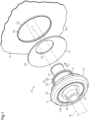
- a grommet 10 shown in Figs. 1 and 2 is attached to a coupling hole Pa, extending through a vehicle body panel P that separates the interior of a passenger compartment from the exterior of the passenger compartment, to protect a wire harness W inserted into the coupling hole Pa.
- the grommet 10 also serves to restrict the entry of water into the coupling hole Pa of the vehicle body panel P.
- the wire harness W includes at least one electric wire.
- An axial direction of the grommet 10 corresponds to the insertion direction in which the wire harness W is inserted through the grommet 10.
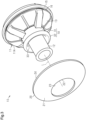
- the grommet 10 includes a grommet body 11 and an umbrella-shaped member 20 that is separate from the grommet body 11.
- the grommet body 11 is inserted into the coupling hole Pa of the vehicle body panel P in the insertion direction D1 that is parallel to axis L.
- the front side and the rear side of the grommet body 11 with respect to the insertion direction D1 may simply be referred to as the front side and the rear side, respectively, or the front side in the axial direction and the rear side in the axial direction, respectively.
- the direction parallel to the axis L, a circumferential direction about the axis L, and a radial direction about the axis L may simply be referred to as the axial direction, the circumferential direction, and the radial direction, respectively.
- the front side in the insertion direction D1 is the passenger compartment interior side of the vehicle body panel P
- the rear side in the insertion direction D1 is the passenger compartment exterior side of the vehicle body panel P.
- a protrusion Pd protrudes around the coupling hole Pa from surface Pb of the vehicle body panel P that is exposed to the passenger compartment exterior side. More specifically, the protrusion Pd protrudes rearward in the insertion direction D1 from around the coupling hole Pa. The protrusion Pd is bent at a substantially right angle with respect to surface Pb of the vehicle body panel P.
- a sound insulator S is attached to surface Pc of the vehicle body panel P.
- the sound insulator S may be a non-woven fabric, a rubber plate, a foamed layer, or the like.
- the sound insulator S includes an insertion hole Sa for insertion of a wire harness at a position corresponding to the coupling hole Pa.
- a covering portion 21 closes the insertion hole Sa of the sound insulator S.
- the grommet body 11 includes, for example, a first grommet 11A and a second grommet 11B coupled to the first grommet 11A.
- the first grommet 11A and the second grommet 11B are separate from each other.
- the first grommet 11A and the second grommet 11B are formed of an elastic material such as rubber.
- the elastic material of the first grommet 11A and the second grommet 11B may be ethylene propylene diene rubber (EPDM).
- EPDM ethylene propylene diene rubber
- the first grommet 11A and the second grommet 11B may be formed from the same elastic material or from different elastic materials. When using different materials, it is preferred that the two elastic materials have flexibility such as rubber or the like.
- the first grommet 11A includes a first tube 12 that is tubular and surrounds the periphery of the wire harness W, a diameter-increasing portion 13 having a diameter that increases toward the rear side from the first tube 12, and a holder 14 holding the umbrella-shaped member 20.
- the first tube 12 has a cross section orthogonal to the axis L of the grommet 10 that is ring-shaped and centered on the axis L.
- the wire harness W is inserted into the first tube 12 in a liquid-tight manner.
- ring refers to any closed outer edge shape formed by connecting straight lines or curved lines and includes a ring having a circular outer edge shape, a ring having an elliptical or oval outer edge shape, a polygonal ring having a polygonal outer shape, and a ring having a polygonal outer edge shape with rounded corners.
- a “ring” is a shape having a hole in a plane view, where the outer edge shape and the shape of the through hole may be the same or different.
- a “ring” has a predetermined length in the direction in which the through hole extends, and the length may be of any dimension.
- the diameter-increasing portion 13 projects from the outer circumferential surface of the first tube 12 and has an increasing diameter.
- the diameter-increasing portion 13 is substantially a circle, the center of which is the axis L, as viewed in the axial direction.
- the diameter-increasing portion 13 has a tapered shape and is increased in diameter toward the rear end in the axial direction.
- the circumferential edge of the diameter-increasing portion 13 is ring-shaped and is in conformance with the edge of the coupling hole Pa.
- a sealing portion 15 is formed on the circumferential edge of the diameter-increasing portion 13.
- the sealing portion 15 is substantially cylindrical and centered on the axis L.
- the outer circumferential surface of the sealing portion 15 includes an outer circumference groove 16 that receives the edge of the coupling hole Pa.
- the outer circumference groove 16, formed over the entire circumference of the sealing portion 15, is ring-shaped and centered on the axis L.
- the outer circumference groove 16 contacts the edge of the coupling hole Pa and seals the gap between the sealing portion 15 and the coupling hole Pa in a liquid-tight manner.
- the first grommet 11A includes a connection piece 17 extending radially inward from the inner circumferential surface of the sealing portion 15.
- the connection piece 17, formed over the entire circumference of the sealing portion 15, is ring-shaped and centered on the axis L.
- the second grommet 11B is coupled to the first grommet 11A to close a rear axial end opening of the first grommet 11A.
- the second grommet 11B includes a second tube 18 surrounding the periphery of the wire harness W and a fixing portion 19 extending outward from the second tube 18.
- the second tube 18 has a cross section orthogonal to the axis L of the grommet 10 that is ring-shaped and centered on the axis L.
- the wire harness W is inserted into the second tube 18 in a liquid-tight manner.
- the second tube 18, for example, has substantially the same diameter as the first tube 12 of the first grommet 11A.
- the fixing portion 19 is formed at, for example, the front end of the second tube 18.
- the fixing portion 19 clamps the connection piece 17 of the first grommet 11A in the axial direction. This connects the fixing portion 19 and the connection piece 17 to fix the second grommet 11B to the first grommet 11A.
- a space is formed inside the grommet body 11. This space improves the sound insulation of the grommet 10.
- the umbrella-shaped member 20 which is separate from the grommet body 11, is arranged on the front side of the diameter-increasing portion 13 of the first grommet 11A.
- the umbrella-shaped member 20 is formed of an elastic material such as rubber.
- the elastic material used for the umbrella-shaped member 20 is, for example, ethylene propylene diene rubber (EPDM).
- EPDM ethylene propylene diene rubber
- the umbrella-shaped member 20 and the grommet body 11 may be formed from the same elastic material or from different elastic material. When using different materials, it is preferred that two elastic materials have flexibility such as rubber or the like.
- the umbrella-shaped member 20 includes the covering portion 21 that covers the insertion hole Sa of the sound insulator S.
- the covering portion 21 is tapered and has a diameter that increases from the front end 22 toward the rear end side in the axial direction.
- the umbrella-shaped member 20 of the present embodiment includes only the tapered covering portion 21.
- the covering portion 21 is, for example, ring-shaped as viewed in the axial direction.
- the covering portion 21 is located outward from the first tube 12.
- the inner circumference edge 23 of the covering portion 21 is, for example, circular and centered on the axis L when viewed in the axial direction.
- the outer circumference of the covering portion 21 is, for example, circular and centered on the axis L as viewed in the axial direction.
- a rear end 24 in the axial direction of the covering portion 21 is configured to elastically abut the sound insulator S.
- the holder 14 of the grommet body 11 is formed at the radially outer side of the first tube 12.
- the holder 14 is, for example, ring-shaped and centered on the axis L.
- the holder 14 includes an extension 31 extending frontward in the axial direction from the diameter-increasing portion 13, and an engagement portion 32 projecting radially outward from the extension 31.
- the extension 31 is, for example, cylindrical and centered on the axis L.
- the extension 31 has a larger outer diameter than the first tube 12.
- the inner circumferential surface of the extension 31 faces the outer circumferential surface of the first tube 12 with a gap 33 in between.
- the front end of the extension 31 is located, for example, toward the rear end of the first tube 12 from the front end of the first tube 12.
- the engagement portion 32 projects radially outward from a front end of the extension 31.
- the engagement portion 32 is, for example, ring-shaped and centered on the axis L. More specifically, the engagement portion 32 extends over the entire circumference of the extension 31. In addition, the engagement portion 32 faces the outer circumferential surface of the first tube 12 with the gap 33 in between.
- the engagement portion 32 includes a projection 34 projecting rearward in the axial direction.
- the projection 34 is formed, for example, at a radially outer end of the engagement portion 32.
- the surface at the radially inner side of the projection 34 is, for example, an inclined surface 35 of which the diameter increases rearward in the axial direction. This narrows the distal end at the rear side of the projection 34.
- the wire harness W is inserted through the grommet body 11 and the umbrella-shaped member 20.
- the wire harness W is inserted through the first tube 12 and the second tube 18 of the grommet body 11, and is inserted through the inner circumference edge 23 of the covering portion 21 of the umbrella-shaped member 20.
- the umbrella-shaped member 20 is not coupled to the grommet body 11, and the grommet body 11 and the umbrella-shaped member 20 are located at the side of surface Pb of the vehicle body panel P.
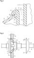
- the umbrella-shaped member 20 at the side of surface Pb of the vehicle body panel P is deformed and passed through the coupling hole Pa of the vehicle body panel P. As shown in Fig. 5 , this disposes the umbrella-shaped member 20 at the side of surface Pc of the vehicle body panel P.
- the grommet body 11 is inserted into the coupling hole Pa of the vehicle body panel P in the insertion direction D1 to couple the grommet body 11 to the coupling hole Pa.
- the diameter-increasing portion 13 of the grommet body 11 is inserted into the coupling hole Pa and deformed radially inward when contacting the edge of the coupling hole Pa.
- the edge of the coupling hole Pa enters the outer circumference groove 16 of the sealing portion 15 in the grommet body 11.
- part of the grommet body 11 is located inside the insertion hole Sa of the sound insulator S.
- at least the front end of the holder 14 projects frontward in the insertion direction D1 from surface Sb of the sound insulator S.
- the umbrella-shaped member 20 is coupled to the grommet body 11, which is coupled to the coupling hole Pa, in a coupling direction D2, which is opposite to the insertion direction D 1.
- the rear end 24 of the covering portion 21 of the umbrella-shaped member 20 first contacts the surface Sb of the sound insulator S.
- the axial dimension of the umbrella-shaped member 20 before being coupled that is, the axial dimension of the covering portion 21 in the present embodiment, is set to be larger than the axial dimension from surface Sb of the sound insulator S to the engagement portion 32 of the holder 14.
- the front end 22 of the covering portion 21 abuts the engagement portion 32 in the axial direction.
- the diameter of the inner circumference edge 23 of the covering portion 21 is set to be larger than the outer diameter of the extension 31 of the holder 14.
- the inner circumference edge 23 of the covering portion 21 faces the extension 31 in the radial direction with a gap X in between.
- part of the inner circumference edge 23 in the circumferential direction may contact the extension 31.
- the projection 34 of the engagement portion 32 is located radially outward from the front end 22 of the covering portion 21. More specifically, the projection 34 faces the outer surface of the covering portion 21 in the radial direction.
- the grommet 10 includes the grommet body 11 including the sealing portion 15 contacting the edge of the coupling hole Pa, and the umbrella-shaped member 20 including the covering portion 21 covering the insertion hole Sa of the sound insulator S.
- the umbrella-shaped member 20 is separate from the grommet body 11. Therefore, after the grommet body 11, which is free from the umbrella-shaped member 20, is coupled to the coupling hole Pa, the umbrella-shaped member 20 can be coupled to the grommet body 11, which is coupled to the coupling hole Pa. This restricts entry of the covering portion 21 into the gap between the grommet body 11 and the coupling hole Pa when inserting the grommet body 11 into the coupling hole Pa.
- the shape of the covering portion 21 as viewed in the axial direction does not have to be circular shape and can be changed to be, for example, elliptical or polygonal in conformance with the shape of the insertion hole Sa of the sound insulator S.
- the umbrella-shaped member 20 of the embodiment described above includes only the tapered covering portion 21.
- the umbrella-shaped member 20 may include a tube that is tubular and extends forward in the axial direction from the inner circumference edge 23 of the covering portion 21.
- the front end of the umbrella-shaped member 20 is the front end of the tubular portion, and the engagement portion 32 is engaged with the front end of the tubular portion in the axial direction.
- the extension 31 and the engagement portion 32 each extend continuously in the circumferential direction. This is not a limitation.
- the extension 31 and the engagement portion 32 may each extend in a non-continuous manner in the circumferential direction.
- the projection 34 may be omitted from the engagement portion 32 of the embodiment described above.
- the extension 31 may be omitted from the grommet body 11 of the embodiment described above, and the engagement portion 32 may be arranged on the outer circumferential surface of the first tube 12.
- the shape of the sealing portion 15 when viewed in the axial direction does not have to be circular and can be changed to, for example, be elliptical in accordance with the shape of the coupling hole Pa.
- the grommet body 11 includes the two components of the first grommet 11A and the second grommet 11B. This is not a limitation.
- the grommet body 11 may include one component.
- the elastic material used for the grommet body 11 and the umbrella-shaped member 20 is not limited to EPDM, and other materials such as NBR (acrylonitrile butadiene rubber) can be used.
- the protrusion Pd at the edge of the coupling hole Pa protrudes outward from the passenger compartment.
- the protrusion Pd may protrude inward into the passenger compartment.
- the grommet body 11 may be configured to be inserted into the coupling hole Pa from inside the passenger compartment.
- the protrusion Pd on the edge of the coupling hole Pa may be inclined relative to the axis L.
- a structure in which the protrusion Pd is omitted from the coupling hole Pa that is, a structure in which the burring process is not applied to the coupling hole Pa may be employed.
- the grommet body 11 may include the extension 31 that is continuous with the engagement portion 32 and has an extension length in the axial direction, and the extension length of the extension 31 of the grommet body 11 may allow the front end 22 of the umbrella-shaped member 20 to move in the axial direction along the extension 31.
- This structure is advantageous in that, for example, the grommet 10 can be applied to sound insulators S of various thicknesses exerting various sound insulating properties.
- the extension 31 may have a tubular outer circumferential surface having a first outer diameter.
- the engagement portion 32 may project radially outward from the extension 31 so as to have a second outer diameter that is larger than the outer diameter of the extension 31.
- the front end 22 of the umbrella-shaped member 20 may include the inner circumference edge 23 that has an inner diameter larger than the outer diameter of the extension 31 and smaller than the outer diameter of the engagement portion 32.
Landscapes
- Engineering & Computer Science (AREA)
- Mechanical Engineering (AREA)
- General Engineering & Computer Science (AREA)
- Installation Of Indoor Wiring (AREA)
- Insulating Bodies (AREA)
Applications Claiming Priority (2)
| Application Number | Priority Date | Filing Date | Title |
|---|---|---|---|
| JP2021027721A JP7344913B2 (ja) | 2021-02-24 | 2021-02-24 | グロメット |
| PCT/JP2022/005441 WO2022181362A1 (ja) | 2021-02-24 | 2022-02-10 | グロメット |
Publications (2)
| Publication Number | Publication Date |
|---|---|
| EP4300519A1 true EP4300519A1 (de) | 2024-01-03 |
| EP4300519A4 EP4300519A4 (de) | 2024-08-21 |
Family
ID=83049195
Family Applications (1)
| Application Number | Title | Priority Date | Filing Date |
|---|---|---|---|
| EP22759401.7A Pending EP4300519A4 (de) | 2021-02-24 | 2022-02-10 | Tülle |
Country Status (5)
| Country | Link |
|---|---|
| US (1) | US12374475B2 (de) |
| EP (1) | EP4300519A4 (de) |
| JP (1) | JP7344913B2 (de) |
| CN (1) | CN116941154A (de) |
| WO (1) | WO2022181362A1 (de) |
Families Citing this family (1)
| Publication number | Priority date | Publication date | Assignee | Title |
|---|---|---|---|---|
| US20240280123A1 (en) * | 2023-02-16 | 2024-08-22 | Illinois Tool Works Inc. | Compressing Snap Grommet |
Family Cites Families (19)
| Publication number | Priority date | Publication date | Assignee | Title |
|---|---|---|---|---|
| JPH0310578Y2 (de) * | 1987-07-15 | 1991-03-15 | ||
| JP2003032854A (ja) * | 2001-07-18 | 2003-01-31 | Yazaki Corp | グロメット |
| US6815615B1 (en) * | 2003-08-29 | 2004-11-09 | Yazaki North America, Inc. | Two-part grommet |
| US7026549B1 (en) * | 2005-02-04 | 2006-04-11 | Delphi Technologies, Inc. | Collapsible grommet |
| JP5266670B2 (ja) * | 2007-06-13 | 2013-08-21 | 住友電装株式会社 | グロメット |
| JP5157513B2 (ja) | 2008-02-20 | 2013-03-06 | 住友電装株式会社 | グロメット |
| JP5098827B2 (ja) * | 2008-06-03 | 2012-12-12 | 住友電装株式会社 | グロメット |
| JP2010006138A (ja) * | 2008-06-24 | 2010-01-14 | Yamaha Motor Co Ltd | 船外機のケーブル挿通構造 |
| JP5163406B2 (ja) | 2008-09-30 | 2013-03-13 | 住友電装株式会社 | グロメット |
| JP5365568B2 (ja) * | 2010-03-31 | 2013-12-11 | 住友電装株式会社 | ワイヤハーネス用のグロメット |
| JP5633353B2 (ja) * | 2010-12-10 | 2014-12-03 | 住友電装株式会社 | グロメット |
| JP2016207358A (ja) | 2015-04-17 | 2016-12-08 | 矢崎総業株式会社 | グロメット |
| JP6688635B2 (ja) * | 2016-03-03 | 2020-04-28 | 矢崎総業株式会社 | グロメット |
| JP2017220976A (ja) | 2016-06-03 | 2017-12-14 | 矢崎総業株式会社 | グロメットの製造方法およびグロメット |
| JP7256466B2 (ja) | 2019-10-30 | 2023-04-12 | 住友電装株式会社 | グロメット |
| JP7268576B2 (ja) * | 2019-10-30 | 2023-05-08 | 住友電装株式会社 | グロメット |
| US20230127049A1 (en) | 2020-03-09 | 2023-04-27 | Sumitomo Wiring Systems, Ltd. | Grommet unit |
| JP7581771B2 (ja) * | 2020-10-28 | 2024-11-13 | 住友電装株式会社 | グロメット |
| US12125610B2 (en) * | 2021-12-06 | 2024-10-22 | Yazaki Corporation | Grommet and wire harness |
-
2021
- 2021-02-24 JP JP2021027721A patent/JP7344913B2/ja active Active
-
2022
- 2022-02-10 CN CN202280015173.3A patent/CN116941154A/zh active Pending
- 2022-02-10 EP EP22759401.7A patent/EP4300519A4/de active Pending
- 2022-02-10 US US18/546,975 patent/US12374475B2/en active Active
- 2022-02-10 WO PCT/JP2022/005441 patent/WO2022181362A1/ja not_active Ceased
Also Published As
| Publication number | Publication date |
|---|---|
| CN116941154A (zh) | 2023-10-24 |
| WO2022181362A1 (ja) | 2022-09-01 |
| US12374475B2 (en) | 2025-07-29 |
| US20240136092A1 (en) | 2024-04-25 |
| JP2022129142A (ja) | 2022-09-05 |
| US20240233988A9 (en) | 2024-07-11 |
| EP4300519A4 (de) | 2024-08-21 |
| JP7344913B2 (ja) | 2023-09-14 |
Similar Documents
| Publication | Publication Date | Title |
|---|---|---|
| US9716377B2 (en) | Electrical wire protection member | |
| CN112744167B (zh) | 护线套 | |
| US9096185B2 (en) | Grommet | |
| US8692122B2 (en) | Grommet | |
| WO2012124203A1 (ja) | グロメットのシール構造 | |
| JP7256466B2 (ja) | グロメット | |
| EP4300519A1 (de) | Tülle | |
| US10300868B2 (en) | Grommet and wire harness | |
| JP7544201B2 (ja) | グロメット | |
| CN112751295B (zh) | 护线套 | |
| US12327660B2 (en) | Grommet | |
| US12583403B2 (en) | Grommet | |
| JP5765101B2 (ja) | グロメット | |
| JPH0992060A (ja) | グロメット | |
| JP7463984B2 (ja) | グロメットアセンブリ及びワイヤハーネス | |
| JPH0992061A (ja) | グロメット | |
| JPH09120727A (ja) | グロメット | |
| CN211480804U (zh) | 护线套、带护线套的拉线以及车门锁体装置 | |
| JP5539087B2 (ja) | ワイヤーハーネス用のグロメット | |
| JP2018078744A (ja) | グロメット | |
| EP2990635A1 (de) | Verbinderanordnung | |
| WO2022186333A1 (ja) | グロメットユニット及びワイヤハーネス | |
| JP2025513909A (ja) | 車両用グロメット装置 | |
| WO2013001670A1 (ja) | パイプハーネスの車体取付構造 |
Legal Events
| Date | Code | Title | Description |
|---|---|---|---|
| STAA | Information on the status of an ep patent application or granted ep patent |
Free format text: STATUS: THE INTERNATIONAL PUBLICATION HAS BEEN MADE |
|
| PUAI | Public reference made under article 153(3) epc to a published international application that has entered the european phase |
Free format text: ORIGINAL CODE: 0009012 |
|
| STAA | Information on the status of an ep patent application or granted ep patent |
Free format text: STATUS: REQUEST FOR EXAMINATION WAS MADE |
|
| 17P | Request for examination filed |
Effective date: 20230818 |
|
| AK | Designated contracting states |
Kind code of ref document: A1 Designated state(s): AL AT BE BG CH CY CZ DE DK EE ES FI FR GB GR HR HU IE IS IT LI LT LU LV MC MK MT NL NO PL PT RO RS SE SI SK SM TR |
|
| DAV | Request for validation of the european patent (deleted) | ||
| DAX | Request for extension of the european patent (deleted) | ||
| A4 | Supplementary search report drawn up and despatched |
Effective date: 20240719 |
|
| RIC1 | Information provided on ipc code assigned before grant |
Ipc: H02G 3/22 20060101ALI20240715BHEP Ipc: B60R 16/02 20060101ALI20240715BHEP Ipc: H01B 17/58 20060101AFI20240715BHEP |