EP4300532A1 - Relais à courant continu haute tension à fonction d'extinction d'arc en acier magnétique - Google Patents
Relais à courant continu haute tension à fonction d'extinction d'arc en acier magnétique Download PDFInfo
- Publication number
- EP4300532A1 EP4300532A1 EP22758758.1A EP22758758A EP4300532A1 EP 4300532 A1 EP4300532 A1 EP 4300532A1 EP 22758758 A EP22758758 A EP 22758758A EP 4300532 A1 EP4300532 A1 EP 4300532A1
- Authority
- EP
- European Patent Office
- Prior art keywords
- permanent magnets
- static
- contact piece
- movable contact
- movable
- Prior art date
- Legal status (The legal status is an assumption and is not a legal conclusion. Google has not performed a legal analysis and makes no representation as to the accuracy of the status listed.)
- Pending
Links
Images








Classifications
-
- H—ELECTRICITY
- H01—ELECTRIC ELEMENTS
- H01H—ELECTRIC SWITCHES; RELAYS; SELECTORS; EMERGENCY PROTECTIVE DEVICES
- H01H9/00—Details of switching devices, not covered by groups H01H1/00 - H01H7/00
- H01H9/30—Means for extinguishing or preventing arc between current-carrying parts
- H01H9/44—Means for extinguishing or preventing arc between current-carrying parts using blow-out magnet
- H01H9/443—Means for extinguishing or preventing arc between current-carrying parts using blow-out magnet using permanent magnets
-
- H—ELECTRICITY
- H01—ELECTRIC ELEMENTS
- H01H—ELECTRIC SWITCHES; RELAYS; SELECTORS; EMERGENCY PROTECTIVE DEVICES
- H01H50/00—Details of electromagnetic relays
- H01H50/16—Magnetic circuit arrangements
- H01H50/36—Stationary parts of magnetic circuit, e.g. yoke
- H01H50/38—Part of main magnetic circuit shaped to suppress arcing between the contacts of the relay
-
- H—ELECTRICITY
- H01—ELECTRIC ELEMENTS
- H01H—ELECTRIC SWITCHES; RELAYS; SELECTORS; EMERGENCY PROTECTIVE DEVICES
- H01H50/00—Details of electromagnetic relays
- H01H50/54—Contact arrangements
- H01H50/546—Contact arrangements for contactors having bridging contacts
-
- H—ELECTRICITY
- H01—ELECTRIC ELEMENTS
- H01H—ELECTRIC SWITCHES; RELAYS; SELECTORS; EMERGENCY PROTECTIVE DEVICES
- H01H50/00—Details of electromagnetic relays
- H01H50/64—Driving arrangements between movable part of magnetic circuit and contact
-
- H—ELECTRICITY
- H01—ELECTRIC ELEMENTS
- H01H—ELECTRIC SWITCHES; RELAYS; SELECTORS; EMERGENCY PROTECTIVE DEVICES
- H01H1/00—Contacts
- H01H1/12—Contacts characterised by the manner in which co-operating contacts engage
- H01H1/14—Contacts characterised by the manner in which co-operating contacts engage by abutting
- H01H1/20—Bridging contacts
-
- H—ELECTRICITY
- H01—ELECTRIC ELEMENTS
- H01H—ELECTRIC SWITCHES; RELAYS; SELECTORS; EMERGENCY PROTECTIVE DEVICES
- H01H9/00—Details of switching devices, not covered by groups H01H1/00 - H01H7/00
- H01H9/30—Means for extinguishing or preventing arc between current-carrying parts
- H01H9/44—Means for extinguishing or preventing arc between current-carrying parts using blow-out magnet
- H01H9/446—Means for extinguishing or preventing arc between current-carrying parts using blow-out magnet using magnetisable elements associated with the contacts
Definitions
- the present disclosure relates to the technical field of a relay, in particular to a high-voltage DC relay with permanent magnet arc extinguishing function.
- the existing DC relays generally adopt a solution of a direct acting movable contact piece (also called a direct acting solenoid) that has contact portions including two static contacts and one movable contact piece.
- the two static contacts are generally installed at a top of a ceramic cap, and have bottom ends (i.e., leading-out terminals of the static contact points) extending into the ceramic cap.
- the movable contact piece is directed acted and distributed within the ceramic cap, and two ends of the movable contact piece serving as movable contacts are respectively cooperated with the two static contacts as the bottom ends of the static contact points.
- the movable contact piece is installed at one end of a pushing rod, and the other end of the pushing rod is connected with a movable iron core of a magnetic part.
- a coil is powered on by the current to make the pushing rod move upwards, the two ends of the movable contact piece are in contact with two static contacts, respectively to communicate with a load.
- the pushing rod moves downwards under the action of a reset spring, and the two ends of the movable contact piece are separated from the two static contacts respectively to cut off the load.
- a permanent magnet is generally employed to extinguish the arc, that is, an arc is blown by using magnetic field generated by arranging permanent magnets around the contacts.
- the most typical permanent magnet configuration is to arrange a permanent magnet outside the either end of the movable contact piece in a length direction, such double permanent magnets have a good arc blowing direction and meet the requirements of non-polarity; however its magnetic field strength is weak (especially at the arc starting point and at a center of the leading-out terminal), so that for large-load products, having a large ceramic cavity, which makes the magnetic field strength of the arc extinguishing part reach the arc starting point small, and then the initial arc extinguishing effect is poor, it may not be possible to extinguish the arc in time under the limited condition. Therefore, the high-voltage DC relay in the prior art cannot satisfy the improvement of a system load for new energy vehicles and energy storage projects.
- An object of the present disclosure is to overcome shortcomings of the prior art.
- a high-voltage DC relay capable of longitudinally drawing arc.
- the structure thereof is improved to strengthen the magnetic field strength at a contact point and to allow Lorentz force at the arcing point always to face a direction favorable for arc extinction, thereby improving an arc extinguishing effect.
- a high-voltage DC relay capable of longitudinally drawing arc includes two static contact leading-out terminals and one movable contact piece; the movable contact piece being arranged under the two static contact leading-out terminals, and two ends of the movable contact piece functioned as movable contacts being respectively cooperated with bottom ends of the two static contact leading-out terminals functioned as static contacts; first permanent magnets being respectively arranged at positions corresponding to the contacts around the movable contact piece, and a side having polarity of each of the first permanent magnets faces the corresponding contact, such that arc extinction is implemented by using a horizontal magnetic field formed by the first permanent magnets; under the movable contact piece, , second permanent magnets are arranged at a position where the static contacts are in contact with the movable contacts, and polarity of a contact-facing sides of the second permanent magnets is opposite to the polarity of the contact-facing sides of the first permanent magnets, such that the
- two first permanent magnets are provided, and the two first permanent magnets are respectively arranged outside the two ends of the movable contact piece in a length direction, the two second permanent magnets are respectively arranged on two sides of the movable contact piece in a length, and each of the two second permanent magnets is arranged between a middle portion of the movable contact piece in the length direction and a position where the static contact is in contact with the movable contact at the corresponding end of the movable contact piece.
- a projection of the second permanent magnet on a reference horizontal plane falls into a projection of an area between the two first permanent magnets on the reference horizontal plane.
- two second permanent magnets corresponding to the positions where the two static contacts are in contact with the movable contacts are an integrated structure.
- two first permanent magnets are provided, and the two first permanent magnets are respectively arranged outside the two ends of the movable contact piece in a length direction.
- An anti-short circuit ring is further provided in the middle portion of the movable contact piece in the length direction.
- the two second permanent magnets are respectively arranged on two sides of the movable contact piece in a length direction, and each of the two second permanent magnets is arranged between an edge of the anti-short circuit ring and a position where the static contact is in contact with the movable contact at the corresponding end of the movable contact piece.
- a projection of the second permanent magnet on a reference horizontal plane falls into a projection of an area between the two first permanent magnets on the reference horizontal plane.
- the bottom of the two ends of the movable contact piece in the length direction are provided with first grooves that are recessed upward right under the positions where the static contacts are correspondingly in contact with the movable contacts, and the two second permanent magnets are respectively embedded into the first grooves at the two ends of the movable contact piece in the length direction.
- a yoke plate is also arranged under the movable contact piece, and each of the two second permanent magnets is provided in an area between the movable contact piece and the yoke plate.
- a yoke plate is further arranged under the movable contact piece, and the two second permanent magnets are respectively mounted on the yoke plate.
- the DC relay further includes two first U-shaped yokes respectively arranged to the two first permanent magnets, a U-shaped bottom wall of each of the two first U-shaped yokes is in contact with a side of the corresponding one of the first permanent magnets facing away from the corresponding contact, and the U-shaped side walls of each of the two first U-shaped yokes are respectively arranged on two sides of the movable contact piece in the width direction and are opposite to the corresponding contacts.
- a projection of the position where the movable contacts are in contact with the static contacts on a reference horizontal plane falls into a projection of the frame-shaped outline surrounded by the first U-shaped yokes on the reference horizontal plane.
- first permanent magnets are provided, and the four first permanent magnets are respectively arranged outside the two ends of the movable contact piece and are opposite to the corresponding static and movable contacts, and polarities of the contact-facing sides of the two first permanent magnets facing the same static and movable contacts are set to be the same; and the two second permanent magnets are respectively arranged under the positions where the two static contacts are correspondingly in contact with the movable contacts.
- a projection of the second permanent magnet on a reference horizontal plane falls into a projection of an area between the two first permanent magnets corresponding to the same static and movable contacts on the reference horizontal plane.
- the two second permanent magnets are located right under the positions where the two static contacts are correspondingly in contact with the movable contacts, and the projection of the second permanent magnets on the reference horizontal plane falls into the projection of the middle connecting lines of the two first permanent magnets corresponding to the same static and movable contacts on the reference horizontal plane.
- the DC relay further includes two second U-shaped yokes arranged on the four first permanent magnets, wherein the U-shaped bottom wall of each of the two second U-shaped yokes corresponds to the outer side of each of the two ends of the movable contact piece in the length direction, and the U-shaped side walls of each of the two second U-shaped yokes are respectively arranged on the two sides of the movable contact piece in the width direction and in contact with one side facing away from the corresponding contacts of the first permanent magnets at the corresponding position.
- the movable contact piece corresponds to the middle portion of each of the first permanent magnets in a height direction.
- the present disclosure further provides a high-voltage DC relay with permanent magnet arc extinguishing function includes two static contact leading-out terminals and one movable contact piece; the movable contact piece being arranged under the two static contact leading-out terminals, and two ends of the movable contact piece functioned as movable contacts being respectively cooperated with bottom ends of the two static contact leading-out terminals functioned as static contacts; first permanent magnets being respectively arranged at positions corresponding to the contacts around the movable contact piece, and a side having polarity of each of the first permanent magnets faces the corresponding contact, such that arc extinction is implemented by using a horizontal magnetic field formed by the first permanent magnets, wherein the third permanent magnets are further installed to a side facing away from the static contacts in the two static contact leading-out terminals, and sides having polarity of the third permanent magnets face the corresponding contacts, and polarity of the sides facing the contacts of the third permanent magnets is opposite to polarity of the sides facing the contacts of the first permanent magnets
- second grooves recessed downward are disposed at upper ends of the static contact leading-out terminals, and the third permanent magnets are embedded into the second grooves to be close to the corresponding contacts.
- the third permanent magnet is circular, a section of the second groove is a circular shape corresponding to that of the third permanent magnet, the third permanent magnet is located in a middle of the static contact leading-out terminals in a respective same horizontal plane.
- the two movable contacts are protrusions integrally formed at the two ends of the movable contact piece.
- two first permanent magnets are provided, and the two first permanent magnets are respectively arranged outside the two ends of the movable contact piece in a length direction; the protrusions at the two ends of the movable contact piece are respectively in eccentric contact with the bottom ends of the two static contact leading-out terminals.
- the protrusions at the two ends of the movable contact piece are respectively arranged at edges of the two ends of the movable contact piece; positions where the two static contact leading-out terminals are in contact with the protrusions at the two ends of the movable contact piece are at an opposite outer side of the bottom ends of the two static contact leading-out terminals.
- the bottom end surface of the static contact leading-out terminal is a circle, and the position where the static contact leading-out terminal is in contact with the protrusion of the movable contact piece does not exceed a center of the circle.
- the DC relay further comprises two first U-shaped yokes respectively arranged on the two first permanent magnets, a U-shaped bottom wall of each of the two first U-shaped yokes is correspondingly in contact with the side of the first permanent magnet facing away from the contact, and two U-shaped side walls of the two first U-shaped yokes are respectively arranged on two sides of the movable contact piece in a width direction and are opposite to the corresponding contacts.
- a projection where the movable contacts are fit to the static contacts on a reference horizontal plane falls into a projection of a frame-shaped outline surrounded by the first U-shaped yokes on the reference horizontal plane.
- first permanent magnets are provided, and the four first permanent magnets are arranged outside the two sides of the movable contact piece in a width direction and are opposite to the corresponding contacts, respectively; and polarities of sides of the two first permanent magnets corresponding to the same contact are set to be the same.
- the DC relay further comprises two second U-shaped yokes arranged on four first permanent magnets, a U-shaped bottom wall of each of the two second U-shaped yokes corresponds to an outer side of each of the two ends of the movable contact piece in a length direction, and two U-shaped side walls of each of the two second U-shaped yokes are respectively arranged on the two sides of the movable contact piece in a width direction and are in contact with the sides of the first permanent magnets facing away from the corresponding contacts.
- the movable contact piece corresponds to a middle portion of each of the first permanent magnets in a height direction.
- a third permanent magnet is installed on a side facing away from the static contacts, and has a side with polarity facing the corresponding contact, and the polarity of the side of the third permanent magnet facing the contact is opposite to the polarity of the side of the first permanent magnet facing the contact, to utilize a longitudinal magnetic field formed by the first permanent magnet and the third permanent magnet at the contact and enhance the magnetic field strength at the contact so as to realize the arc extinction.
- the structure as disclosed by the present disclosure can improve the longitudinal arc striking magnetic field, improve the central magnetic field strength at the leading-out terminals, and accelerate the speed of extinguishing the arc by blowing magnet at the moment of the arc striking.
- two movable contacts are configured as protrusions integrally formed at both ends of the movable contact piece, and the protrusions at both ends of the movable contact piece are eccentrically contacted with bottom ends of the leading-out terminals of the two static contacts, respectively.
- Such configuration of the present disclosure can strengthen the magnetic field strength at the contact points through the cooperation of the longitudinal arc magnetic field and the eccentric contact points, and allow the Lorentz force at an arcing point to always side a direction favorable for the arc extinction, thereby improving the arc extinguishing effect.
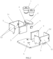
- a high-voltage DC relay capable of longitudinally drawing arc includes two static contact leading-out terminals 1 and one movable contact piece 2.
- the movable contact piece 2 is arranged under the two static contact leading-out terminals 1, and both ends of the movable contact piece 2 that are configured as movable contacts are respectively cooperated with the bottom ends of the two static contact leading-out terminals 1 which are configured as static contacts.
- First permanent magnets 3 are respectively arranged at positions where the static contacts are correspondingly in contact with the movable contacts around the movable contact piece 2, and a side having polarity of the first permanent magnet 3 faces the corresponding static and movable contacts, such that the arc extinction can be implemented by using a horizontal magnetic field formed by the first permanent magnets 3.
- second permanent magnets 4 are arranged at the contact position corresponding to each of the static and movable contacts, and polarity of a side of the second permanent magnet 4 facing the static and movable contacts is opposite to the polarity of the contact-facing sides of the first permanent magnets 3, such that the magnetic field strength at the contacts can be enhanced by using a longitudinal magnetic field formed by the first permanent magnets 3 and the second permanent magnets 4 at the static and movable contacts, and further the arc extinction can be implemented.
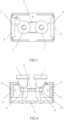
- first permanent magnets 3 there are two first permanent magnets 3, and the two first permanent magnets 3 are respectively arranged outside the two ends of the movable contact piece 2 in a length direction, the two second permanent magnets 4 are respectively arranged on two sides of the movable contact piece 2 in a length, and each of the two second permanent magnets 4 is arranged under a position between a middle portion of the movable contact piece 2 in the length direction and the contact position of the static and movable contacts at the corresponding end of the movable contact piece.
- a projection of the second permanent magnet 4 on a reference horizontal plane falls into a projection of an area between the two first permanent magnets 3 (i.e., the area surrounded by a connecting line of both sides in a width direction of the two first permanent magnets 3) on the reference horizontal plane.
- the bottom of the two ends of the movable contact piece 2 in the length direction are provided with first grooves 21 that are recessed upward right under the positions where the static contacts are correspondingly in contact with the movable contacts, and the two second permanent magnets 4 are respectively embedded into the first grooves 21 at the two ends of the movable contact piece 2 in the length direction.
- a magnetic polarity of a contact-facing side of two first permanent magnets 3 corresponding to one end (a left end) of the movable contact piece 2 is referred to as S-pole
- a magnetic polarity of a contact-facing side of two first permanent magnets 3 corresponding to the other end (a right end) of the movable contact piece 2 is referred to as S-pole
- a magnetic polarity of a contact-facing side (an upward side) of the second permanent magnet 4 corresponding to one end (a left end) of the movable contact piece 2 is referred to as N-pole
- a magnetic polarity of a contact-facing side (an upward side) of the second permanent magnet 4 corresponding to the end (a right end) of the movable contact piece 2 is referred to as N-pole.
- the DC relay further includes two first U-shaped yokes 5 arranged to the two first permanent magnets 3, wherein each of the U-shaped bottom walls 51 of the two first U-shaped yokes 5 is in contact with one side of the corresponding first permanent magnet 3 facing away from the corresponding contact, and the U-shaped side walls 52 of the two first U-shaped yokes are respectively arranged on two sides of the movable contact piece 2 in the width direction and are opposite to the corresponding contacts.
- projections of the contact positions of the static and movable contacts on the reference horizontal plane fall into the projection of a frame-shaped outline surrounded by the first U-shaped yoke 5 on the reference horizontal plane.
- the movable contact piece 2 corresponds to a middle position in a height direction of the first permanent magnet 3.
- a yoke plate 6 is further arranged under the movable contact piece 2.
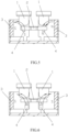
- the second permanent magnets 4 are at the contact positions of the static and movable contacts, and the polarity of the side of the second permanent magnet 4 facing the static and movable contacts is opposite to the polarity of the side of the first permanent magnet 3 facing the static and movable contact, such that the magnetic field strength at the contacts can be enhanced by using the longitudinal magnetic field formed by the first permanent magnet 3 and the second permanent magnet 4 at the static and movable contacts as indicated by arrows in Fig. 4 , and further the arc extinction can be implemented.
- Such configuration of this disclosure can improve a longitudinal arcing magnetic field, improve a central magnetic field strength of the leading-out terminals, and accelerate a speed of magnetic blowing arc extinction at an arcing moment.
- two second permanent magnets 4 are respectively embedded into the first grooves 21 at both ends of the movable contact piece 2 in the length direction, that is, the second permanent magnets 4 are located in an area between the lower side of the movable contact piece and the yoke plate 6, and a U-shaped yoke 5 is also arranged on the first permanent magnet.
- the strength of the longitudinal magnetic field between the first permanent magnet 3 and the second permanent magnet 4 can be enhanced, and the longitudinal arcing magnetic field can be further enhanced, the central magnetic field strength of the leading-out terminals can be improved, and the magnetic blowing arc extinction speed at the arcing moment can be further accelerated.
- a high-voltage DC relay capable of longitudinally drawing arc is different from that of the first embodiment in that magnetic polarities of the contact-facing sides of two first permanent magnets 3 are set to be different, and a magnetic polarity of one contact-facing side of two first permanent magnets 3 corresponding to one end (a left end) of the movable contact piece 2 is configured as S pole, and a magnetic polarity of one contact-facing side of two first permanent magnets 3 corresponding to the other end (a right end) of the movable contact piece 2 is configured as N pole; a magnetic polarity of one contact-facing side (an upward side) of the second permanent magnet 4 corresponding to one end (a left end) of the movable contact piece 2 is configured as N pole, and a magnetic polarity of one contact-facing side (an upward side) of the second permanent magnet 4 corresponding to the other end (a right end) of the movable contact piece 2 is configured as S pole.
- a high-voltage DC relay capable of longitudinally drawing arc according to the present disclosure is different from that of the first embodiment in that two second permanent magnets 4 have different installation positions, and the two second permanent magnets 4 are not installed on the bottom of the two ends of the movable contact piece 2 in the length direction, but are installed in an area between the movable contact piece 2 and the yoke plate 6.
- the second permanent magnet 4 in this embodiment is more downward than the second permanent magnet 4 in the first embodiment in position, it is required to adjust the second permanent magnet 4 horizontally to be close to the middle portion of the movable contact piece 2 in the length direction, instead of being right under the contact positions of the static and movable contacts, to ensure that the magnetic lines of the longitudinal magnetic field formed by the first permanent magnets 3 and the second permanent magnets 4 can pass through the center of the leading-out terminals.
- a high-voltage DC relay capable of longitudinally drawing arc according to the present disclosure is different from that of the first embodiment in that the two second permanent magnets 4 have different installation positions.
- the two second permanent magnets 4 are not installed on the bottom of the two ends of the movable contact piece 2 in the length direction, but are installed on the yoke plate 6, respectively.
- the second permanent magnet 4 in this embodiment is more downward than the second permanent magnet 4 in the first embodiment in position, it is required to adjust the second permanent magnet 4 horizontally to be close to the middle portion of the movable contact piece 2 in the length direction, instead of being right under the contact positions of the static and movable contacts, to ensure that the magnetic lines of the longitudinal magnetic field formed by the first permanent magnets 3 and the second permanent magnets 4 can pass through the center of the leading-out terminals.
- the second permanent magnets 4 are mounted on the yoke plate 6, and the first U-shaped yokes 5 are arranged on the first permanent magnets 3.
- the strength of the longitudinal magnetic field between the first permanent magnet 3 and the second permanent magnet 4 can be enhanced, and the longitudinal arcing magnetic field can be further enhanced, the central magnetic field strength of the leading-out terminals can be improved, and the magnetic blowing arc extinction speed at the arcing moment can be further accelerated.
- a high-voltage DC relay capable of longitudinally drawing arc is different from that of the fourth embodiment in that magnetic polarities of the contact-facing sides of two first permanent magnets 3 are set to be different, and a magnetic polarity of one contact-facing side of two first permanent magnets 3 corresponding to one end (a left end) of the movable contact piece 2 is configured as S pole, and a magnetic polarity of one contact-facing side of two first permanent magnets 3 corresponding to the other end (a right end) of the movable contact piece 2 is configured as N pole; a magnetic polarity of one contact-facing side (an upward side) of the second permanent magnet 4 corresponding to one end (a left end) of the movable contact piece 2 is configured as N pole, and a magnetic polarity of one contact-facing side (an upward side) of the second permanent magnet 4 corresponding to the other end (a right end) of the movable contact piece 2 is configured as S pole.
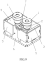
- a high-voltage DC relay capable of longitudinally drawing arc is different from that of the first embodiment in that an anti-short circuit ring 7 is further installed at the middle position of the movable contact piece 2 in a length, since the anti-short circuit ring 7 is provided, each of the second permanent magnets 4 is arranged between an edge of the anti-short circuit ring 7 and a position that is right under the contact position of the static and movable contacts at the corresponding end thereof, and the second permanent magnets 4 are also embedded into the first grooves 21 of the movable contact piece 2.
- the anti-short circuit ring 7 is formed by the cooperation of two " " " shaped upper armatures 71 and two U-shaped lower armatures 72.
- a through hole 22 penetrating through the thickness of the movable contact piece 2 is arranged in the middle of the movable contact piece 2 in a length
- two " " shaped upper armatures 71 are usually fixed on the top of a U-shaped bracket of a pushing rod of the relay by riveting or welding
- two U-shaped lower armatures 72 are respectively fixed on the movable contact piece 2 by riveting
- side walls of the two U-shaped lower armatures 72 pass through the through hole 22 of the movable contact piece 2
- the top ends of the two U-shaped lower armatures 72 are exposed out of the upper side of the movable contact piece to be cooperated with the two " " shaped upper armatures 71, and a closed magnetic loop is formed in an annular piece formed by the " " shaped upper armatures 71 and the U-shaped lower armatures 72
- a high-voltage DC relay capable of longitudinally drawing arc is different from that of the first embodiment in that there are four first permanent magnets 3, and the four first permanent magnets 3 are respectively arranged outside the two ends of the movable contact piece 2 and are opposite to the corresponding static and movable contacts, and polarities of sides of the two first permanent magnets 3 facing the same static and movable contacts are set to be the same; and the two second permanent magnets 4 are respectively arranged under the positions where the two static contacts are correspondingly in contact with the movable contacts.
- a projection of the second permanent magnet 4 on a reference horizontal plane falls into a projection of an area between the two first permanent magnets 3 corresponding to the same static and movable contacts on the reference horizontal plane.
- the two second permanent magnets 4 are located right under the positions where the two static contacts are correspondingly in contact with the movable contacts, and the projection of the second permanent magnets 4 on the reference horizontal plane falls into the projection of the middle connecting lines of the two first permanent magnets corresponding to the same static and movable contacts on the reference horizontal plane.
- the DC relay further includes two second U-shaped yokes 8 arranged on the four first permanent magnets 3, wherein the U-shaped bottom wall 81 of each of the two second U-shaped yokes 8 corresponds to the outer side of each of the two ends of the movable contact piece 2 in the length direction, and the U-shaped side walls 82 of each of the two second U-shaped yokes 8 are respectively arranged on the two sides of the movable contact piece 2 in the width direction and in contact with one side facing away from the corresponding contact of the first permanent magnets 3 at the corresponding position.
- the magnetic polarity of the contact-facing sides of the two first permanent magnets 3 corresponding to one end (a left end) of the movable contact piece 2 is referred to as N pole, and the magnetic polarity of contact-facing sides of the two first permanent magnets 3 corresponding to the other end (a right end) of the movable contact piece 2 is also referred to as N pole; and the magnetic polarity of the contact-facing sides (upper sides) of the second permanent magnets 4 corresponding to one end (a left end) of the movable contact piece 2 is referred to as S pole, and the magnetic polarity of the contact-facing sides (upper sides) of the second permanent magnets 4 corresponding to the other end (a right end) of the movable contact piece 2 is referred to as S pole.
- a high-voltage DC relay capable of longitudinally drawing arc is different from that of the seventh embodiment in that the magnetic polarities of the contact-facing sides of the four first permanent magnets 3 are different, and the magnetic polarity of the contact-facing sides of the two first permanent magnets 3 corresponding to one end (a left end) of the movable contact piece 2 is referred to as S pole, and the magnetic polarity of contact-facing sides of the two first permanent magnets 3 corresponding to the other end (a right end) of the movable contact piece 2 is also referred to as N pole; and a similar adjustment is made to the contact-facing sides of the second permanent magnets 4, the magnetic polarity of the contact-facing sides (upper sides) of the second permanent magnets 4 corresponding to one end (a left end) of the movable contact piece 2 is referred to as N pole, and the magnetic polarity of the contact-facing sides (upper sides) of the second permanent magnets 4 corresponding to the other end (a right end
- a high-voltage DC relay capable of longitudinally drawing arc according to the present disclosure is different from that of the seventh embodiment in that an anti-short circuit ring 7 is also installed in the middle position of the movable contact piece 2 in the length direction.
- the present disclosure further provides a high-voltage DC relay with permanent magnet arc extinguishing function, including two static contact leading-out terminals 1 and one movable contact piece 2.
- the movable contact piece 2 is arranged under the two static contact leading-out terminals 1, and both ends of the movable contact piece 2 that are configured as movable contacts are respectively cooperated with the bottom ends of the two static contact leading-out terminals 1 which are configured as static contacts.
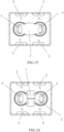
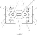
- First permanent magnets 3 are respectively arranged outside the two ends of the movable contact piece 2 in the length direction, and a side having polarity of the first permanent magnet 3 faces the corresponding contacts, such that the arc extinction can be implemented by using a horizontal magnetic field formed by each of the first permanent magnets 3 (as shown in Fig. 19 ).
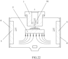
- third permanent magnets 91 are installed on a side facing away from the static contacts, and sides of the third permanent magnets 91 having polarity facing the corresponding contacts, and the polarity of the contact-facing sides of the third permanent magnets 91 is opposite to the polarity of the contact-facing sides of the first permanent magnets, so that the magnetic field strength at the contacts can be enhanced by a longitudinal magnetic field formed by the first permanent magnets 3 and the third permanent magnets 91 (as shown in Figure 20 ), and then the arc extinction can be further implemented.
- the magnetic polarity of the contact-facing sides of the first permanent magnets 3 corresponding to one end of the movable contact piece 2 is referred to as N pole, and the magnetic polarity of contact-facing sides of the first permanent magnets 3 corresponding to the other end of the movable contact piece 2 is also referred to as S pole; and the magnetic polarity of the contact-facing sides of the third permanent magnets 91 corresponding to one end of the movable contact piece 2 is referred to as S pole, and the magnetic polarity of the contact-facing sides of the first permanent magnets 3 corresponding to the other end of the movable contact piece 2 is referred to as N pole.
- second grooves 11 that are recessed downwards are provided on the upper ends of the leading-out terminals 1 of the two stationary contacts, respectively.
- the third permanent magnets 91 are embedded into the second grooves 11 to be close to the corresponding contacts.
- the third permanent magnets 91 are circular; the second groove 11 has a circular cross section corresponding to that of the second permanent magnet; the third permanent magnets 91 are located in the middle of the static contact leading-out terminals 1 in the corresponding same horizontal plane.
- the two movable contacts are protrusions 23 integrally formed at both ends of the movable contact piece 2, and the protrusions 23 at both ends of the movable contact piece 2 are in eccentric contact with the bottom ends of the two static contact leading-out terminals 1, respectively.
- the protrusion 23 is formed after being struck by the movable contact piece 2 along a thickness direction.
- the protrusions 23 at the two ends of the movable contact piece 2 are respectively arranged at edges of the two ends of the movable contact piece; and the contact positions 12 of the two static contact leading-out terminals 1 and the protrusions 23 at both ends of the movable contact piece are at the opposite outer sides of the bottom ends of the two static contact leading-out terminals.
- the bottom end surface of the static contact leading-out terminals 1 is circular, and the contact position 12 between the static contact leading-out terminals 1 and the protrusion 23 of the movable contact piece 2 does not exceed a center of the circle, that is, the bottom end surface of the static contact leading-out terminals 1 is eccentrically contacted with the protrusion 23 of the movable contact piece 2.
- the movable contact piece 2 corresponds to the middle position in the height of the first permanent magnet 3.
- the DC relay further includes two first U-shaped yokes 5 respectively arranged on two first permanent magnets, wherein the U-shaped bottom walls 51 of the two first U-shaped yokes 5 are respectively in contact with sides facing away from the corresponding contacts of the corresponding first permanent magnets 3, and the U-shaped side walls 52 of the two first U-shaped yokes 5 are respectively arranged on two sides of the movable contact piece 2 in the width direction and are opposite to the corresponding contacts.
- a projection of a position where the movable contacts are cooperated with the stationary contacts on the reference horizontal plane falls into a projection of the frame-shaped outline surrounded by the first U-shaped yokes 5 on the reference horizontal plane.
- the third permanent magnets 91 are provided to the side facing away from the static contacts, the side of the third permanent magnet 91 having polarity sides the corresponding contacts, and the polarity of the contact-facing side of the third permanent magnet 91 is opposite to the polarity of the contact-facing side of the first permanent magnet 3, such that the magnetic field strength at the contacts can be enhanced by using the longitudinal magnetic field formed by the first permanent magnets 3 and the third permanent magnets 91 at the contacts, and then the arc extinction can be implemented.
- the longitudinal arcing magnetic field can be improved, the central magnetic field strength at the leading-out terminals can be improved, and the speed of magnetic blowing arc extinction at the arcing moment can be increased.
- two movable contacts are set as protrusions 23 integrally formed at both ends of the movable contact piece 2, and the protrusions 23 at both ends of the movable contact piece 2 are eccentrically contacted with the bottom ends of the two static contact leading-out terminals 1, respectively.
- the magnetic field strength at the contacts can be strengthened through the cooperation of the longitudinal arcing magnetic field and the eccentric contacts, and allow the Lorentz force at the arcing point to always side a direction favorable for the arc extinction, thereby improving the arc extinguishing effect.
- the magnetic polarity of the contact-facing sides of the first permanent magnets 3 corresponding to one end of the movable contact piece 2 is referred to as N pole, and the magnetic polarity of contact-facing sides of the first permanent magnets 3 corresponding to the other end of the movable contact piece 2 is also referred to as S pole; and of course, the magnetic polarity of the contact-facing sides of the first permanent magnets 3 corresponding to one end of the movable contact piece 2 is referred to as S pole, and the magnetic polarity of the contact-facing sides of the first permanent magnets 3 corresponding to the other end of the movable contact piece 2 is referred to as N pole, or the contact-facing sides of the two first permanent magnets 3 are all set as N pole or S pole.
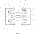
- a high-voltage DC relay with permanent magnet arc extinguishing function is different from that of the tenth embodiment in that there are four first permanent magnets 3.
- the four first permanent magnets 3 are respectively arranged outside the two sides of the movable contact piece 2 in the width direction and opposite to the corresponding contacts, and the polarities of the contact-facing sides of the two first permanent magnets 3 corresponding to the same contact are set to be the same.
- the magnetic polarities of contact-facing sides of the two first permanent magnets 3 corresponding to one end of the movable contact piece 2 are referred to as N poles
- the magnetic polarities of contact-facing sides of the two first permanent magnets 3 corresponding to the other end of the movable contact piece 2 are referred to as S poles
- the magnetic polarities of the contact-facing sides of the third permanent magnets 91 corresponding to one end of the movable contact piece 2 are referred to as S poles
- the magnetic polarities of the contact-facing sides of the first permanent magnets 3 corresponding to the other end of the movable contact piece 2 are referred to as N poles.
- the DC relay further includes two second U-shaped yokes 6 arranged on the four first permanent magnets 3, the U-shaped bottom walls 61 of the two second U-shaped yokes 6 respectively correspond to the outer side of each of the two ends of the movable contact piece 2 in the length direction, and the U-shaped side walls 62 of the two second U-shaped yokes 6 are respectively arranged on the two sides of the movable contact piece 2 in the width direction, and are in contact with one sides facing away from the corresponding contacts of the first permanent magnets 3 at the corresponding positions.
- the magnetic polarities of the contact-facing sides of the two first permanent magnets 3 corresponding to one end of the movable contact piece 2 are referred to as N poles, and the magnetic polarities of the contact-facing sides of the two first permanent magnets 3 corresponding to the other end of the movable contact piece 2 are referred to as S poles; of course, the magnetic polarities of the contact-facing sides of the two first permanent magnets 3 corresponding to one end of the movable contact piece 2 may be referred to as S poles, and the magnetic polarities of the contact-facing sides of the two first permanent magnets 3 corresponding to the other end of the movable contact piece 2 may be referred to as N poles, or the contact-facing sides of the four first permanent magnets 3 may be set as N poles or S poles.
- first permanent magnets 3 In the case that the contact-facing sides of the four first permanent magnets 3 are set as N poles or S poles, two first permanent magnets 3 on the same side corresponding to the width of the movable contact piece 2 may be connected as a whole.
Landscapes
- Physics & Mathematics (AREA)
- Electromagnetism (AREA)
- Arc-Extinguishing Devices That Are Switches (AREA)
Applications Claiming Priority (3)
| Application Number | Priority Date | Filing Date | Title |
|---|---|---|---|
| CN202110220485.5A CN113178359B (zh) | 2021-02-26 | 2021-02-26 | 一种带磁钢灭弧的高压直流继电器 |
| CN202110807850.2A CN113808884B (zh) | 2021-07-16 | 2021-07-16 | 一种可纵向拉弧的高压直流继电器 |
| PCT/CN2022/075540 WO2022179393A1 (fr) | 2021-02-26 | 2022-02-08 | Relais à courant continu haute tension à fonction d'extinction d'arc en acier magnétique |
Publications (2)
| Publication Number | Publication Date |
|---|---|
| EP4300532A1 true EP4300532A1 (fr) | 2024-01-03 |
| EP4300532A4 EP4300532A4 (fr) | 2024-12-25 |
Family
ID=83048663
Family Applications (1)
| Application Number | Title | Priority Date | Filing Date |
|---|---|---|---|
| EP22758758.1A Pending EP4300532A4 (fr) | 2021-02-26 | 2022-02-08 | Relais à courant continu haute tension à fonction d'extinction d'arc en acier magnétique |
Country Status (5)
| Country | Link |
|---|---|
| US (1) | US12562320B2 (fr) |
| EP (1) | EP4300532A4 (fr) |
| JP (2) | JP7594120B2 (fr) |
| KR (1) | KR20230104683A (fr) |
| WO (1) | WO2022179393A1 (fr) |
Families Citing this family (4)
| Publication number | Priority date | Publication date | Assignee | Title |
|---|---|---|---|---|
| KR20240051061A (ko) * | 2022-10-12 | 2024-04-19 | 샤먼 홍파 일렉트릭 파워 컨트롤즈 컴퍼니 리미티드 | 릴레이 |
| CN118675944A (zh) * | 2023-03-17 | 2024-09-20 | 厦门宏发电力电器有限公司 | 一种继电器 |
| CN118675938A (zh) * | 2023-03-17 | 2024-09-20 | 厦门宏发电力电器有限公司 | 一种继电器触头磁屏蔽结构和继电器 |
| CN121464497A (zh) * | 2023-08-10 | 2026-02-03 | 皮尔伯格有限责任公司 | 高压接触器或高压继电器 |
Family Cites Families (24)
| Publication number | Priority date | Publication date | Assignee | Title |
|---|---|---|---|---|
| FR2480028A1 (fr) * | 1980-04-04 | 1981-10-09 | Merlin Gerin | Interrupteur a arc tournant par action d'un aimant permanent |
| WO1992017897A1 (fr) | 1991-03-28 | 1992-10-15 | Kilovac Corporation | Dispositif de relais sous vide a courant continu |
| US5519370A (en) | 1991-03-28 | 1996-05-21 | Kilovac Corporation | Sealed relay device |
| JP5223499B2 (ja) | 2008-06-30 | 2013-06-26 | オムロン株式会社 | 電磁継電器 |
| JP5437949B2 (ja) | 2010-08-11 | 2014-03-12 | 富士電機機器制御株式会社 | 接点装置及びこれを使用した電磁接触器 |
| JP2012038684A (ja) * | 2010-08-11 | 2012-02-23 | Fuji Electric Fa Components & Systems Co Ltd | 接点装置及びこれを使用した電磁開閉器 |
| US8653691B2 (en) * | 2011-01-13 | 2014-02-18 | GM Global Technology Operations LLC | Dual bipolar magnetic field for linear high-voltage contactor in automotive lithium-ion battery systems |
| KR101216824B1 (ko) | 2011-12-30 | 2012-12-28 | 엘에스산전 주식회사 | 직류 릴레이 |
| JP5938745B2 (ja) * | 2012-07-06 | 2016-06-22 | パナソニックIpマネジメント株式会社 | 接点装置および当該接点装置を搭載した電磁継電器 |
| CN103515153B (zh) * | 2013-08-07 | 2016-12-28 | 浙江宏舟新能源科技有限公司 | 一种可靠灭弧的无极性高压直流接触器灭弧系统 |
| CN104882335B (zh) | 2015-03-31 | 2017-07-28 | 厦门宏发电力电器有限公司 | 一种磁钢错位分布的灭弧磁路及其直流继电器 |
| CN106960766B (zh) | 2017-05-09 | 2018-09-07 | 浙江英洛华新能源科技有限公司 | 导弧式拍合式继电器 |
| JP6926787B2 (ja) | 2017-07-31 | 2021-08-25 | 日本製鉄株式会社 | 鉄心構造体、トランス、及び鉄損抑制方法 |
| JP7047662B2 (ja) | 2018-08-10 | 2022-04-05 | オムロン株式会社 | リレー |
| CN109671593B (zh) | 2018-12-28 | 2024-05-14 | 厦门宏发电力电器有限公司 | 一种带磁钢灭弧并能够抗短路电流的直流继电器 |
| CN109659198B (zh) | 2018-12-28 | 2024-05-14 | 厦门宏发电力电器有限公司 | 一种灭弧及抗短路电流的直流继电器 |
| CN209658107U (zh) * | 2019-03-06 | 2019-11-19 | 深圳巴斯巴汽车电子有限公司 | 一种无极性电磁继电器 |
| KR102339179B1 (ko) | 2019-07-11 | 2021-12-14 | 엘에스일렉트릭 (주) | 아크 경로 형성부 및 이를 포함하는 직류 릴레이 |
| CN110690079B (zh) | 2019-08-27 | 2025-04-08 | 浙江宏舟新能源科技有限公司 | 一种方形环氧封装的高压直流继电器 |
| CN111091987B (zh) * | 2019-12-31 | 2025-04-04 | 厦门宏发电力电器有限公司 | 一种能够抗短路电流及灭弧的直流继电器 |
| CN113178359B (zh) * | 2021-02-26 | 2025-08-12 | 厦门宏发电力电器有限公司 | 一种带磁钢灭弧的高压直流继电器 |
| CN214505390U (zh) | 2021-02-26 | 2021-10-26 | 厦门宏发电力电器有限公司 | 带磁钢灭弧的高压直流继电器 |
| KR20220162465A (ko) * | 2021-06-01 | 2022-12-08 | 현대자동차주식회사 | 고내구 전기 접점 구조 |
| CN215869142U (zh) | 2021-07-16 | 2022-02-18 | 厦门宏发电力电器有限公司 | 可纵向拉弧的高压直流继电器 |
-
2022
- 2022-02-08 JP JP2023536011A patent/JP7594120B2/ja active Active
- 2022-02-08 WO PCT/CN2022/075540 patent/WO2022179393A1/fr not_active Ceased
- 2022-02-08 US US18/547,399 patent/US12562320B2/en active Active
- 2022-02-08 EP EP22758758.1A patent/EP4300532A4/fr active Pending
- 2022-02-08 KR KR1020237019225A patent/KR20230104683A/ko active Pending
-
2024
- 2024-11-21 JP JP2024203020A patent/JP7854029B2/ja active Active
Also Published As
| Publication number | Publication date |
|---|---|
| JP2025019173A (ja) | 2025-02-06 |
| JP7594120B2 (ja) | 2024-12-03 |
| KR20230104683A (ko) | 2023-07-10 |
| WO2022179393A1 (fr) | 2022-09-01 |
| EP4300532A4 (fr) | 2024-12-25 |
| JP7854029B2 (ja) | 2026-04-30 |
| US12562320B2 (en) | 2026-02-24 |
| US20240145188A1 (en) | 2024-05-02 |
| JP2023552893A (ja) | 2023-12-19 |
Similar Documents
| Publication | Publication Date | Title |
|---|---|---|
| EP4300532A1 (fr) | Relais à courant continu haute tension à fonction d'extinction d'arc en acier magnétique | |
| JP7601492B2 (ja) | 短絡電流に耐え、消弧することができる直流リレー | |
| EP2711964B1 (fr) | Mécanisme de contact et contacteur électromagnétique l'utilisant | |
| CN115332016A (zh) | 一种能够抗短路电流及灭弧的直流继电器 | |
| CN212032904U (zh) | 能够抗短路电流及灭弧的直流继电器 | |
| CN214505390U (zh) | 带磁钢灭弧的高压直流继电器 | |
| CN113178359B (zh) | 一种带磁钢灭弧的高压直流继电器 | |
| EP4401106A1 (fr) | Relais à courant continu (dc) à haute tension capable d'améliorer la capacité d'extinction d'arc | |
| CN113808884B (zh) | 一种可纵向拉弧的高压直流继电器 | |
| CN215869142U (zh) | 可纵向拉弧的高压直流继电器 | |
| CN216435800U (zh) | 一种带抗短路结构的高压直流继电器 | |
| CN103093987A (zh) | 用于低压开关的磁性组件 | |
| CN109920704B (zh) | 抗洛仑兹力继电器 | |
| CN110010416B (zh) | 一种抗洛仑兹力继电器 | |
| CN219842931U (zh) | 增加爬电距离的继电器 | |
| CN216435773U (zh) | 具有增磁组件的触头系统、断路器和隔离开关 | |
| JP2002237242A (ja) | 電磁継電器 |
Legal Events
| Date | Code | Title | Description |
|---|---|---|---|
| STAA | Information on the status of an ep patent application or granted ep patent |
Free format text: STATUS: THE INTERNATIONAL PUBLICATION HAS BEEN MADE |
|
| PUAI | Public reference made under article 153(3) epc to a published international application that has entered the european phase |
Free format text: ORIGINAL CODE: 0009012 |
|
| STAA | Information on the status of an ep patent application or granted ep patent |
Free format text: STATUS: REQUEST FOR EXAMINATION WAS MADE |
|
| 17P | Request for examination filed |
Effective date: 20230821 |
|
| AK | Designated contracting states |
Kind code of ref document: A1 Designated state(s): AL AT BE BG CH CY CZ DE DK EE ES FI FR GB GR HR HU IE IS IT LI LT LU LV MC MK MT NL NO PL PT RO RS SE SI SK SM TR |
|
| DAV | Request for validation of the european patent (deleted) | ||
| DAX | Request for extension of the european patent (deleted) | ||
| REG | Reference to a national code |
Ref country code: DE Ref legal event code: R079 Free format text: PREVIOUS MAIN CLASS: H01H0050380000 Ipc: H01H0009440000 |
|
| A4 | Supplementary search report drawn up and despatched |
Effective date: 20241125 |
|
| RIC1 | Information provided on ipc code assigned before grant |
Ipc: H01H 50/38 20060101ALN20241119BHEP Ipc: H01H 1/20 20060101ALN20241119BHEP Ipc: H01H 50/54 20060101ALI20241119BHEP Ipc: H01H 9/44 20060101AFI20241119BHEP |