EP4303376A2 - Trappe de révision et procédé de fabrication d'une trappe de révision - Google Patents
Trappe de révision et procédé de fabrication d'une trappe de révision Download PDFInfo
- Publication number
- EP4303376A2 EP4303376A2 EP23205517.8A EP23205517A EP4303376A2 EP 4303376 A2 EP4303376 A2 EP 4303376A2 EP 23205517 A EP23205517 A EP 23205517A EP 4303376 A2 EP4303376 A2 EP 4303376A2
- Authority
- EP
- European Patent Office
- Prior art keywords
- attachment
- inspection flap
- outer frame
- plate
- frame
- Prior art date
- Legal status (The legal status is an assumption and is not a legal conclusion. Google has not performed a legal analysis and makes no representation as to the accuracy of the status listed.)
- Pending
Links
- 238000007689 inspection Methods 0.000 title claims abstract description 120
- 238000000034 method Methods 0.000 title claims description 12
- 238000004519 manufacturing process Methods 0.000 title claims description 7
- 238000005253 cladding Methods 0.000 claims abstract description 46
- 239000000463 material Substances 0.000 claims abstract description 46
- 229910052751 metal Inorganic materials 0.000 claims description 10
- 239000002184 metal Substances 0.000 claims description 10
- 229910052782 aluminium Inorganic materials 0.000 claims description 4
- XAGFODPZIPBFFR-UHFFFAOYSA-N aluminium Chemical compound [Al] XAGFODPZIPBFFR-UHFFFAOYSA-N 0.000 claims description 4
- 239000006260 foam Substances 0.000 claims description 3
- 101001017827 Mus musculus Leucine-rich repeat flightless-interacting protein 1 Proteins 0.000 description 30
- 239000003795 chemical substances by application Substances 0.000 description 5
- 238000005187 foaming Methods 0.000 description 5
- 230000007246 mechanism Effects 0.000 description 5
- QVGXLLKOCUKJST-UHFFFAOYSA-N atomic oxygen Chemical compound [O] QVGXLLKOCUKJST-UHFFFAOYSA-N 0.000 description 4
- 239000010440 gypsum Substances 0.000 description 4
- 229910052602 gypsum Inorganic materials 0.000 description 4
- 239000001301 oxygen Substances 0.000 description 4
- 229910052760 oxygen Inorganic materials 0.000 description 4
- 238000007789 sealing Methods 0.000 description 4
- 238000010276 construction Methods 0.000 description 3
- 239000002557 mineral fiber Substances 0.000 description 3
- 239000000779 smoke Substances 0.000 description 3
- 231100000331 toxic Toxicity 0.000 description 3
- 230000002588 toxic effect Effects 0.000 description 3
- 229910000831 Steel Inorganic materials 0.000 description 2
- 238000005520 cutting process Methods 0.000 description 2
- 230000001066 destructive effect Effects 0.000 description 2
- 239000003063 flame retardant Substances 0.000 description 2
- 238000009434 installation Methods 0.000 description 2
- 238000005192 partition Methods 0.000 description 2
- 230000008569 process Effects 0.000 description 2
- 230000002441 reversible effect Effects 0.000 description 2
- 239000000565 sealant Substances 0.000 description 2
- 239000010959 steel Substances 0.000 description 2
- 239000002341 toxic gas Substances 0.000 description 2
- XLYOFNOQVPJJNP-UHFFFAOYSA-N water Substances O XLYOFNOQVPJJNP-UHFFFAOYSA-N 0.000 description 2
- OKTJSMMVPCPJKN-UHFFFAOYSA-N Carbon Chemical compound [C] OKTJSMMVPCPJKN-UHFFFAOYSA-N 0.000 description 1
- 238000004026 adhesive bonding Methods 0.000 description 1
- 238000004378 air conditioning Methods 0.000 description 1
- 229910052918 calcium silicate Inorganic materials 0.000 description 1
- 239000000378 calcium silicate Substances 0.000 description 1
- OYACROKNLOSFPA-UHFFFAOYSA-N calcium;dioxido(oxo)silane Chemical compound [Ca+2].[O-][Si]([O-])=O OYACROKNLOSFPA-UHFFFAOYSA-N 0.000 description 1
- 230000000295 complement effect Effects 0.000 description 1
- 238000011161 development Methods 0.000 description 1
- 230000018109 developmental process Effects 0.000 description 1
- 230000000694 effects Effects 0.000 description 1
- 239000000835 fiber Substances 0.000 description 1
- 239000011094 fiberboard Substances 0.000 description 1
- 230000009970 fire resistant effect Effects 0.000 description 1
- 239000003517 fume Substances 0.000 description 1
- 239000007789 gas Substances 0.000 description 1
- 239000010439 graphite Substances 0.000 description 1
- 229910002804 graphite Inorganic materials 0.000 description 1
- 239000007770 graphite material Substances 0.000 description 1
- 230000036541 health Effects 0.000 description 1
- 230000002427 irreversible effect Effects 0.000 description 1
- 238000003698 laser cutting Methods 0.000 description 1
- 238000012423 maintenance Methods 0.000 description 1
- 239000007769 metal material Substances 0.000 description 1
- 238000010422 painting Methods 0.000 description 1
- 230000008092 positive effect Effects 0.000 description 1
- 238000004080 punching Methods 0.000 description 1
- 230000008439 repair process Effects 0.000 description 1
- 238000009423 ventilation Methods 0.000 description 1
- 239000002699 waste material Substances 0.000 description 1
Images



Classifications
-
- E—FIXED CONSTRUCTIONS
- E04—BUILDING
- E04F—FINISHING WORK ON BUILDINGS, e.g. STAIRS, FLOORS
- E04F19/00—Other details of constructional parts for finishing work on buildings
- E04F19/08—Built-in cupboards; Masks of niches; Covers of holes enabling access to installations
-
- E—FIXED CONSTRUCTIONS
- E04—BUILDING
- E04B—GENERAL BUILDING CONSTRUCTIONS; WALLS, e.g. PARTITIONS; ROOFS; FLOORS; CEILINGS; INSULATION OR OTHER PROTECTION OF BUILDINGS
- E04B9/00—Ceilings; Construction of ceilings, e.g. false ceilings; Ceiling construction with regard to insulation
- E04B9/003—Ceilings; Construction of ceilings, e.g. false ceilings; Ceiling construction with regard to insulation with movable parts, e.g. pivoting panels, access doors
Definitions
- the invention relates to an inspection flap for reversibly closing an opening in a wall and ceiling cladding.
- ceiling coverings or wall coverings; in the following, for the sake of simplicity, we will generally only speak of ceiling coverings
- openings at regular intervals which serve, for example, to be able to reach hidden supply lines, be they for energy, water or air are provided in the cavity between the cladding and the actual load-bearing ceiling. This makes it possible to inspect, maintain, repair or replace the lines without having to remove the entire cladding in this area and/or irreversibly damaging the cladding.
- These openings are reversibly closed with so-called inspection flaps.
- fire safety regulations of buildings stipulate that the walls of fire compartments or shaft walls or suspended ceilings must be covered with fire-retardant or at least high-temperature and/or flame-resistant materials in order to prevent the rapid spread of any fire. These materials are usually mats or panels of fireproof fibrous or foamed materials. Since, according to legal regulations, the entire (ceiling) cladding must be flame-resistant or fire-retardant, this also applies to the inspection flaps.
- the inspection flaps known from practice are inserted into openings in (wall, shaft or) ceiling cladding and, in the event of necessary intervention, are opened by opening, for example unfolding or removing, the flap.
- the fireproof material is often placed as a plate on a substructure of the ceiling cladding in the area of the inspection flap, so that it has to be removed from it and put to the side when the inspection flap is opened.
- the flame-resistant board must then be placed back on the substructure. Opening and re-closing the inspection flaps is therefore difficult and time-consuming and it cannot be ruled out that the flame-resistant panel is not attached or is not attached correctly to the substructure and/or on the top of the inspection flap before the inspection flap is closed.
- such a solution is not suitable for wall cladding, as it has no support surface on the inspection hatch, which is installed vertically in this case.
- the tightness of the opening is usually not guaranteed even after the inspection flap has been closed.
- the cladding is essentially flame and gas-tight. Only through such tightness can it be guaranteed that a fire or smoldering fire that occurs behind the ceiling paneling will not be supplied with unlimited amounts of (fire-promoting) oxygen.
- the flames and smoke resulting from the fire must not escape unhindered through the ceiling cladding in the area of the opening closed with an inspection flap, because such a smoke escape can spread toxic gases over large areas of a building complex and thus directly affect the health of those in it endanger people staying in the building complex.
- an inspection flap for reversibly closing an opening in a wall or ceiling cladding, the inspection flap having an outer frame which can be connected to the wall or ceiling cladding in a form-fitting, non-positive and/or material-locking manner, wherein a inner frame is dismountable and/or pivotably arranged in the outer frame, wherein an at least partially fire-protected plate, in particular a high-temperature and/or flame-resistant plate, is arranged in the inner frame in such a way that it essentially covers an opening formed by the inner frame fills, whereby on the side of the outer frame facing away from a visible side, a circumferential outer attachment made of a fire protection material is arranged, which is connected to the outer frame in a non-positive, positive and / or material fit, the outer attachment being at least indirectly connected to the outer frame - and/or non-positively connected, in particular screwed.
- the inspection flap according to the invention is particularly advantageous because the fact that the outer attachment is firmly connected to the frame and is not just placed on it makes it possible to install the inspection flap according to the invention in wall cladding of buildings. Furthermore, the outer attachment and the outer frame are advantageously connected to one another, so that after using the inspection flap according to the invention there is no risk of the flame-resistant material not being applied or not being applied correctly.
- the outer attachment is particularly preferably reversibly connected to the outer frame. This is particularly advantageous since the outer attachment can thus be separated from the outer frame in a particularly simple manner in one or more parts. For example, if the outer attachment is damaged, it can be separated from the outer frame and replaced with little effort. In addition, handling, particularly when assembling the inspection flap according to the invention, is significantly simplified.
- the inspection flap according to the invention also ensures a high level of safety against flames breaking through the wall and ceiling cladding and against the escape of smoke or other toxic gases.
- Wall and ceiling cladding within the meaning of the present invention can be any type of cladding made of rigid materials.
- Such wall and ceiling claddings are preferably made of a gypsum material. These materials are usually in the form of standardized plates.
- the wall or ceiling cladding is made by putting these standard panels together.
- the wall and ceiling cladding then offers the possibility of laying and maintaining supply lines in existing buildings flexibly and tailored to individual needs, without having to pry open the walls of the building. It is also possible to pull two such wall coverings into a room as independent partitions and thus divide the room individually. In such a case, the supply lines are laid between two wall coverings. Externally, such walls cannot be distinguished from the original walls of the rooms, especially when the surfaces are treated with wallpaper and/or painting.
- the term wall and ceiling cladding also includes any type of partition walls that are assembled in the manner described above or in a comparable manner, if they have an opening that can be closed by an inspection flap.
- a wall or ceiling cladding together with the wall or ceiling (or another wall cladding), forms a cavity in which, for example, the supply lines mentioned are arranged.
- the visible side of an inspection flap is always the side facing away from this cavity, i.e. the side that a user sees in the room in which the inspection flap is installed.
- this is usually the underside of the inspection flap, while the top is the side of the inspection flap that is not visible from the outside.
- the person skilled in the art will recognize that the terms apply analogously in the case of an inspection flap installed in a wall cladding, i.e. in particular essentially vertically.
- fire protection regulations may be designed differently in different countries, and/or the fire protection regulations for a specific country may be adjusted over time. For example, it may happen in particular that certain materials that were approved as fire protection materials at a certain point in time are no longer approved at a later point in time.
- Relevant building law fire protection regulations Examples include DIN EN 520, DIN 18180 and DIN EN 13501-1.
- relevant parameters are in particular the fire behavior, for example A2 for "non-combustible", and the fire protection class, for example F90 for "at least 90 minutes of fire resistance”.
- a plasterboard fire protection board (GKF for short) is provided as the fire protection material, in particular a GKF for fire protection structures (DF for short), so DF/GKF is particularly intended as the fire protection material.
- DF/GKF is available as a material from numerous manufacturers and is easy to process, lightweight and a very suitable material from a fire protection perspective.
- other fire protection materials can also be used, for example mineral fiber boards, calcium silicate boards, gypsum fiber boards and/or fleece-reinforced gypsum plasterboards.
- the at least partially fire-protected panel is a fire protection panel, with the panel particularly preferably having at least one of the fire protection materials mentioned above.
- a fire protection panel does not have to be arranged over the entire surface of the panel.
- Particularly preferably only one plate is arranged in the inner frame.
- at least, in particular precisely, two plates are arranged in the inner frame.
- a cladding panel is particularly preferably arranged on the visible side and a fire protection panel is arranged on the side facing away from the visible side.
- the inspection flap preferably has a size of at least 200mm x 200mm and in particular at most 600mm x 600mm.
- the inspection flap, the outer attachment, the inner attachment, the inner frame and/or the at least partially fire-protected panel have a thickness of essentially 12.5mm, 15mm, 18mm or 20mm. The expert understands that greater thickness usually correlates with better fire protection. It is therefore advantageously possible to provide an inspection flap that is, on the one hand, thin and therefore has a low weight and, on the other hand, also has sufficient thickness for good fire protection.
- the outer attachment has at least one receiving means that interacts with a fastening means, the receiving means preferably being a nut and/or the fastening means of a screw.
- the receiving means is particularly preferably introduced into the outer attachment, for example pressed in.
- the screw is a metric screw.
- a screwless fastening method is used, for example a cohesive fastening method, in particular gluing.
- the fastening means is a tab and the receiving means is a correspondingly complementary opening, so that the outer attachment is plugged and/or clamped onto the outer frame.
- the fastening means is connected to the receiving means via an angle perforated plate in such a way that the main axis of extension of the fastening means is aligned parallel to the main extension plane of the inspection flap, the angle perforated plate being formed in one piece with the inner frame or force-, shape- - and/or cohesively connected.
- An angled perforated sheet metal should be understood to mean, in particular, a sheet metal part that is bent at a right angle and has at least one hole through which the fastening means is passed in order to be connected to the receiving means.
- the sheet is a steel sheet.
- the angled perforated plate therefore interacts with the fastening means (and indirectly with the receiving means) in such a way that a positive and/or non-positive connection is created between the outer attachment and the outer frame.
- the fact that the fastening means is inserted and fastened parallel to the surface of the inspection flap makes a particularly simple attachment possible, which is also not visible from the visible side of the inspection flap.
- the proposed new type of fastening can be easily carried out when the inspection flap is open and is not visible from the outside when the inspection flap is closed.
- the at least one angular perforated plate is inserted into a corresponding profile groove of the outer frame in a positive and/or non-positive manner.
- the angle perforated plate has an elongated hole, in particular a diagonal one relative to the main extension plane of the inspection flap extended slot. This makes it possible in a particularly advantageous manner to take into account a tolerance in the connection between the outer attachment and the outer frame in order to ensure a reliably stable and secure connection.
- the outer attachment is connected to the outer frame via not more than ten, preferably not more than seven, particularly preferably not more than five, in particular not more than four, fastening points. This is particularly advantageous because it enables particularly quick and easy assembly, but at the same time ensures a secure and firm connection between the outer frame and the outer attachment.
- the outer attachment is composed of several rectilinear elements of the fire protection material.
- the elements are preferably slatted and/or strip-shaped.
- the elements can have any cross-section, but preferably the elements comprise a substantially rectangular cross-section. This makes it possible in an advantageous manner to produce and provide the elements in a particularly simple manner, while at the same time almost any shape of the outer attachment can be produced. The production is easier, in particular compared to an external attachment milled from a plate of fire protection material or produced in some other way, and produces less waste.
- the outer attachment particularly preferably comprises at least four elements, most preferably at least eight elements. Even more preferably, the outer cap comprises fewer than ten elements.
- the elements are particularly preferably made from a DF/GKF fire protection board, in particular with a thickness of 15mm.
- the individual parts of the outer attachment are connected without screws, in particular clamped.
- the elements are particularly preferably connected by a large number of brackets, in particular of different lengths.
- the brackets each comprise two legs arranged parallel to one another and a connecting piece arranged and/or aligned essentially at right angles to the main extension direction of the legs, the connecting piece connecting the two legs to one another at one end.
- the legs are of the same length and/or longer than the connecting piece.
- the legs and the connecting piece are preferably formed in one piece.
- the brackets are made of a metallic material.
- the clamps are essentially U-shaped.
- the outer attachment includes clips of different lengths.
- the connection using clamps is advantageously quick, easy and permanently stable.
- clips of different lengths it is also advantageously possible to connect different thicknesses and/or different numbers of elements to one another.
- a comparatively long bracket can be used to connect three elements together and a comparatively short bracket can be used to connect two elements together.
- the attachment is preferably designed as a separate and/or stable part. This makes it particularly easy to detach it from the outer frame and replace it without having to remove the individual elements individually and/or without having to remove the inspection flap from the ceiling paneling.
- a circumferential inner attachment made of a fire protection material is arranged, which is connected to the plate in a non-positive, positive and / or material fit, the inner attachment preferably is arranged adjacent to, in particular separated from, the outer attachment only by an air gap.
- the inner attachment is preferably formed in one piece, in particular unlike the outer attachment.
- the inner attachment is composed of several, in particular straight, elements. In this case, it is preferred if the individual elements are cohesively connected to one another, in particular glued.
- the inner attachment is particularly preferably provided in the form of a frame.
- the inner attachment has a predetermined width and is provided adjacent to an air gap between the inner and outer frame, but is not arranged over the entire area of the plate. This means in particular that there is an internal area of the plate on which the inner attachment is not arranged.
- the inner attachment advantageously further improves fire protection.
- the frame-like structure also advantageously further reduces the weight of the inspection flap.
- the inner attachment is preferably glued to the plate. This provides a permanent and stable connection, which advantageously ensures that the inner attachment is always arranged in the correct position and is not accidentally positioned at all or incorrectly after the inspection flap has been opened and reclosed.
- the outer attachment and the inner attachment are flush with one another on the side facing away from the plate.
- the outer attachment and the inner attachment are particularly preferably of the same height. This advantageously further improves fire protection and ensures a uniform appearance.
- the outer attachment has a substantially L-shaped cross section. What is meant in particular is a cross section along a plane perpendicular to the main extension plane of the inspection flap, the plane preferably containing the center of the inspection flap.
- a first section of the outer attachment is arranged along an outer edge of the outer frame, in particular at a right angle to the main extension plane of the inspection flap, with a second section being located at an upper end of the first section, in particular at a right angle to the first section. extends inwards, i.e. in particular in the direction of the inner frame.
- the outer frame is completely protected from a fire in the cavity of the ceiling or wall cladding, while at the same time a cavity remains above the inner area of the outer frame in order to carry out necessary work.
- the outer frame and/or the inner frame comprises a metal profile, in particular an aluminum profile.
- a metal profile in particular an aluminum profile.
- Such metal profiles are easy to produce and stable.
- Aluminum in particular is a comparatively light material, so that the weight of the inspection flap is advantageously low.
- the plate and/or the inner attachment comprises a fibrous and/or foamed material.
- the plate and/or the inner attachment comprises at least one of the fire protection materials already mentioned at the beginning.
- the inner attachment is made from a mineral fiber board, for example from ROKU ® Therm, a building board that is manufactured and sold by the company Rolf Kuhn GmbH. In this way, an environmentally friendly and well-insulating inner attachment is advantageously provided, which at the same time offers good fire protection properties.
- the plate is made of DF/GKF. The board therefore has good fire protection properties and is comparatively light.
- the inspection flap in particular between the inner frame and the outer frame and / or between the outer attachment and the inner attachment, has at least one air gap, at least one means being arranged in the air gap, which closes the air gap in the event of a fire, preferably at least two means being arranged one behind the other and at a distance from one another.
- the at least one means is arranged all around. This prevents air supply through the inspection flap in a particularly advantageous manner and thus further improves the fire protection properties of the inspection flap.
- the agent is provided such that it increases its volume above a predetermined temperature, wherein the agent is preferably provided such that it foams and/or swells above a predetermined temperature.
- the volume is increased in such a way that the agent fills and seals the air gap in which it is arranged.
- the foaming material is designed in such a way that, after reaching the temperature required for foaming, it foams very quickly and very strongly, particularly preferably up to 7 times its original volume, and the foaming process is carried out at higher temperatures for a specific period Time, preferably more than one hour, particularly preferably at least 90 minutes.
- the rapid foaming preferably takes place above a first temperature, for example at least approximately 100°C, and the further foaming occurs above a second temperature, for example at least 150°C.
- the sealing can therefore take place depending on the temperatures occurring in the area of the opening. It also ensures that the greatest possible sealing effect is achieved at particularly high temperatures.
- this sequential arrangement of the means provides additional security in the sense of technical redundancy. If flames from a fire should penetrate the seal created by the first means, a further seal is provided by the second means.
- the means is particularly preferably band-shaped and/or flexible.
- the agent comprises expandable graphite.
- a suitable material is, for example, the product ROKU ® Strip, which is manufactured and sold by the company Rolf Kuhn GmbH.
- the inspection flap comprises at least one reversible lock, in particular a lock that can be operated from the visible side, the lock being between a locked state in which the inner frame with the inside inserted plate is positively and / or non-positively connected, and an unlocked state in which the inner frame with the plate inserted therein is movable relative to the outer frame, in particular pivotable or foldable and / or removable.
- the inner frame and the outer frame are connected via at least one hinge to simplify and guide the movement of the inner frame.
- the inspection flap preferably includes safety mechanisms and/or dampers in a known manner in order to avoid rapid and/or uncontrolled opening. This can improve operational safety.
- a further subject of the present invention is a method for producing an inspection flap according to the invention, the outer attachment being produced in a first step, the outer attachment being connected to the outer frame in a force-fitting, positive and/or material-locking manner in a second step, wherein in a third step the plate is fastened in the inner frame, wherein in a fourth step the inner frame is dismantled and / or pivotably arranged in the outer frame.
- the method is particularly advantageous because the attachment can be manufactured separately and can then be connected to the outer frame. This can also be done on site, especially if the external attachment is to be replaced.
- the method according to the invention can also be a method for assembling an inspection flap according to the invention.
- the outer frame is inserted into a ceiling and/or wall paneling before the fourth step and fastened there, for example glued, screwed and/or nailed.
- all steps in the manufacture of the access panel are carried out and the fully assembled inspection panel is delivered to a construction site.
- the inner frame with the plate can be removed and the outer frame with the attachment can be installed in the ceiling paneling. The inner frame is then connected again to the outer frame, for example hung.
- the outer attachment in the first step is assembled from, in particular rectilinear, elements and the elements are connected to one another in a form-fitting, force-fitting and/or material-locking manner, in particular clamped.
- this should be understood in particular to mean that pin-like clips are driven through the elements and hold the elements together, similar to nails.
- inserting the staples is quicker and easier than connecting by nailing. Since the pin-like legs of a clip, as is preferably used, are particularly preferably significantly thinner than a nail, such a clip can be inserted into the elements with significantly less effort or force.
- the elements are preferably arranged according to the predetermined shape of the outer attachment and then connected to each other by inserting the clamps. In this way, an outer attachment that can be flexibly produced in different sizes is provided and can also be produced quickly and easily.
- a circumferential inner attachment made of a fire protection material is connected to the plate in a force-fitting, positive and/or material-locking manner, in particular glued , wherein the inner attachment is preferably arranged adjacent to and in particular separated from the outer attachment only by an air gap.
- the fire protection of the inspection flap according to the invention is advantageously further improved.
- the outer attachment is connected to the outer frame, in particular via an angle perforated plate connected to the outer frame in a force-fitting, form-fitting and/or material-locking manner, by means of a fastening means, in particular a screw, is connected, wherein the outer attachment has a receiving means, in particular a nut, which interacts with the fastening means, wherein preferably a main extension axis of the fastening means is aligned parallel to a main extension plane of the inspection flap.
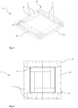
- FIG 1 is a perspective top view of an inspection flap 1 shown according to an exemplary embodiment of the present invention.
- Such an inspection flap 1 is usually inserted into an opening in a ceiling or wall paneling.
- a cavity is formed between the ceiling or wall cladding and the associated component, for example a ceiling or a wall, in which lines can be arranged.
- These can be, for example, water pipes, electrical cables and/or gas pipes.
- Other components such as sprinkler systems and/or ventilation or air conditioning systems, can also be arranged in such an intermediate space. It is crucial that there is access to this gap, for example for maintenance purposes. A non-destructive access option is desirable. To do this, an opening is made in the ceiling or wall cladding and an inspection flap 1 is installed in the opening.
- an inspection flap 1 usually includes an outer frame 2, via which it is firmly connected to the ceiling or wall cladding.
- An inner frame 3 is movably arranged in the outer frame 2.
- movable usually means that the inner frame 3 can be pivoted or folded out of the outer frame 2.
- the inspection flap 1 can include hinges, for example.
- the outer frame 2 and/or the inner frame 3 are preferably designed as metal profiles, in particular aluminum profiles.
- the opening in the wall or ceiling cladding is a weak point through which the fire can spread into the adjacent room, toxic fumes can penetrate into the room and, conversely, oxygen can get from the room into the gap , which feeds the fire.
- the inspection flap 1 withstands a fire as well as possible and also seals the opening as well as possible, at least in the event of a fire.
- the plate 4 is firmly connected to the inner frame 3 and fulfills several functions.
- the plate 4 represents the largest visible area of the inspection flap 1 in the direction of the room. This side is therefore the visible side A of the inspection flap 1. Consequently, it is desirable that the plate 4 on the visible side fits as closely as possible to the adjacent one Wall or ceiling cladding is adapted. Therefore, a similar material is preferably chosen for the plate 4 as for the cladding.
- a fire-protected plate 4 in particular a high-temperature and/or flame-resistant plate 4, is preferably used there. It is known to arrange two plates with different properties one above the other. However, one plate 4 is preferably sufficient.
- the outer frame 2 and the inner frame 3 are poorly protected against heat as metal profiles.
- an outer attachment 5, which is preferably made of a fire protection material, is firmly connected to the outer frame 2.
- the outer attachment 5 is designed here in a frame-like and circumferential manner.
- the outer attachment 5 is also advantageously formed in several parts, in particular from a large number of slat-shaped elements 6, 6 '.
- Several elements 6, 6'(6", etc.) can be of the same design, in particular have the same dimensions, but at least two elements 6, 6' are preferably shaped differently, in particular they have different dimensions.
- the individual elements 6, 6' are connected to one another in a form-fitting and/or non-positive manner by clamps 7, 7'.
- brackets 7, 7' are preferably used, which have two legs aligned parallel to one another and in particular of the same length, which are connected at an upper end by a cross piece are, especially at a right angle. Two, three or more elements 6, 6 'can be connected to one another using a bracket 7.
- brackets 7, 7' of different lengths, so that a suitable bracket 7, 7' can be selected depending on the position.
- the outer attachment 5 is firmly, in particular positively, non-positively and/or materially connected to the outer frame 3 in a manner to be described in more detail.
- the outer attachment 5 has a fire protection material and is preferably made in one piece from such a fire protection material.
- a suitable such fire protection material is, for example, a plasterboard fire protection board for fire protection constructions, DF/GKF for short.
- the outer attachment 5 significantly improves the fire protection of the inspection flap 1 and in particular of the outer frame 2. Because the outer attachment 5 is provided in several parts, the outer attachment 5 can be manufactured easily, flexibly and quickly to suit different inspection flap sizes, without having to stock different sizes.
- the outer attachment 5 protects in particular the outer frame 2. As has already been explained, it is also important to seal the air gap existing between the outer frame 2 and the inner frame 3 or to prevent the passage of toxic vapors in one direction and oxygen in that direction to prevent other direction. Furthermore, it is also desirable to protect the inner frame 3.
- the inspection flap 1 here preferably further comprises an inner attachment 11, which is arranged within the outer attachment 5 on the plate 4 (and possibly partially on the inner frame 3) and is connected to the plate 4 in terms of force, shape and/or is cohesively connected.
- the inner attachment 11 is particularly preferably glued to the plate 4. In this way, a secure and stable connection is provided and repeated opening and closing of the inspection flap 1 does not cause the inner attachment 11 to loosen and possibly tilt.
- the inner attachment 11 preferably has a fire-resistant material, particularly preferably a high-temperature and/or flame-resistant material.
- the inner attachment 11 is made of a fibrous fire protection material, in particular a mineral fiber board, for example ROKUOTherm from Rolf Kuhn GmbH.
- the inner attachment 11 is here also formed in several pieces, in particular from four essentially identically shaped elements. Alternatively, a one-piece design is also possible.
- ceiling or wall cladding is not shown for the sake of clarity.
- cladding is well known and usually includes, in particular standardized, gypsum (fibre) panels.
- the present invention is advantageously intended for use in both a ceiling covering and a wall covering.
- the person skilled in the art understands that when used in a ceiling panel, it is usually arranged essentially horizontally and the inspection flap 1 is accordingly also inserted essentially horizontally into the ceiling panel.
- the visible side A corresponds to a bottom and the opposite side B to a top.
- the exemplary illustrations are usually shown with reference to such an installation situation. Spatial or directional information such as “upon”, “over”, etc. are therefore related to such an orientation.
- the inspection flap 1 preferably opens downwards, i.e. into the space underneath the ceiling paneling.
- the inspection flap 1 according to the invention can also be used advantageously in a wall cladding.
- the inspection flap 1 is usually inserted essentially vertically, i.e. with a main extension plane parallel to a vertical.
- the firm connection between the outer attachment 5 and the outer frame 2 and/or between the inner attachment 11 and the inner frame 3 ensures that fire protection is also guaranteed in such an installation position and not, for example, in the direction of the gap, i.e. on the side facing away B, falls off.
- the expert recognizes that the relevant information has an analogous equivalent if it is installed in wall cladding.
- FIG 2 is a perspective bottom view of an inspection flap 1 according to an exemplary embodiment of the present invention.
- the embodiment shown corresponds to that in Figure 1 embodiment shown.
- the corresponding statements therefore also apply to this embodiment unless a deviation is expressly stated.
- the outer attachment 5 can again be seen, consisting of several elements 6, 6 '.
- the inner frame 3 and/or the plate 4 can have a closure 12, via which the inspection flap 1 can be reversibly locked from the visible side A.
- the closure 12 is a latch that can be moved between a locked position, in which the inner frame 3 together with the plate 4 is not movable relative to the outer frame 2, and an unlocked position, in which the inner frame 2 and the plate 4 can be pivoted downwards, is rotatable, in particular by approximately 90 °.
- a cladding panel can be attached to the visible side A of the plate 4, for example screwed or glued, in order to provide a uniform and aesthetically pleasing overall appearance in the ceiling cladding.
- FIG 3 1 is a perspective schematic view of an outer cap 5 according to an exemplary embodiment of the present invention.
- the elements 6, 6' are shown partially translucent in order to illustrate the internal structure of the outer attachment 5.
- the outer attachment 5 comprises, for example, 10 elements 6, 6 ', some of which are identical to one another and some of which are designed differently.
- the outer attachment 5 can also include more or fewer elements 6, 6 '.
- the outer attachment 5 is preferably provided in such a way that it has a substantially L-shaped cross section, in particular along a cutting plane perpendicular to the main extension plane.
- the upper elements 6 shown here in the illustration are wider than the elements 6 'underlying them, i.e. those adjacent to the outer frame 2.
- the outer attachment 5 projects inwards, i.e. in the direction of the plate 4. In this way, a cavity is provided between the outer frame 2 and the outer attachment 5, so that, for example, fastening elements or other elements, in particular of the outer frame 2, can be accessed.
- the elements 6, 6 ' are connected by a large number of brackets 7, 7' of different lengths.
- receiving means for fasteners are introduced here on the inner side of the outer attachment 5, here in the form of nuts 8, by means of which the outer attachment 5 can be connected to the outer frame 2.
- Such nuts 8 can, for example, be pressed into the material of the outer attachment 5, preferably before assembling the outer attachment 5.
- all the elements 6, 6 'are arranged accordingly and the brackets 7, 7' are inserted in such a way and in sufficient numbers to to form the outer attachment 5 shown here.
- the outer attachment 5 is preferably inherently stable, ie it can be picked up and placed on the outer frame 2 without any problems.
- FIG 4 is a top view of an inspection flap 1 shown according to an exemplary embodiment of the present invention.
- the embodiment shown corresponds to that in connection with the previous ones Figures 1 to 3 explained embodiments.
- the corresponding statements therefore also apply to this embodiment.
- the form of representation presented here and the recognizable elements essentially correspond to those in connection with Figure 1 explained embodiment. Reference is therefore made to the relevant statements here.
- the inspection flap 1, in particular the outer attachment 5 has a substantially square shape with an edge length of approximately 357mm.
- the upper elements 6, 6 'visible here have a width of approximately 57mm.
- a cutting line running from bottom to top in the middle of the illustration is indicated.
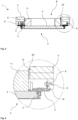
- FIG 5 a schematic cross section of an inspection flap 1 is shown according to an exemplary embodiment of the present invention.
- the embodiment shown corresponds to that in connection with Figures 1 to 2 and especially that Figures 3 and 4 explained embodiments. The corresponding statements therefore also apply to this embodiment. It can be clearly seen in the cross section how the outer attachment 5 projects inwards and forms a cavity together with the outer frame 2 and the inner attachment 11.
- connection between the outer frame 2 and the outer attachment 5 takes place, here by a screw 9, which protrudes at a right angle from the outer frame 2 and acts with it , positively and / or cohesively connected or even formed in one piece with this, angle perforated plate 10, which is in connection with the Figures 11a -e will be explained in more detail, guided and screwed into a nut 8.
- the overhanging area of the outer attachment 5 is formed by two elements 6 lying one above the other.
- these elements 6 have, for example, a height of 15mm, which means that standardized DF/GKF panels can advantageously be used to produce the elements 6, 6 ', with the outer attachment 5 having a total height (at the outer edge) of approximately 55mm.
- a small offset in particular of approximately 3 mm, is provided between the upper edge of the outer attachment 5 and the upper edge of the inner attachment 11.
- the inner attachment 11 and the outer attachment 5 it is possible for the inner attachment 11 and the outer attachment 5 to be flush with one another at the top. As a result, the air gap 20 existing between the attachments 5, 11 is further extended, which has a positive effect on fire protection.
- a means 14 is arranged in the air gap 20. This is preferably provided in such a way that in the event of a fire it closes the air gap 20 and thus prevents the passage of toxic vapors and/or oxygen.
- the agent 14 preferably seals the air gap, so it is a sealant.
- the means 14 is designed in such a way that its volume increases above a certain temperature, in particular suddenly.
- it can include, for example, an expanded graphite material.
- a fire protection strip is used, which is glued all around the upper side edge of the inner attachment 11, e.g. the product ROKUOStrip from Rolf Kuhn GmbH.
- the means 14 does not interfere, i.e. it does not prevent the relative movement of the inner attachment 11 and outer attachment 5 when opening and closing the inspection flap 1, but in the event of a fire it largely completely closes the air gap 20.
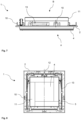
- FIG 7 is a side view of an inspection flap 1 without an external attachment 5 shown according to an exemplary embodiment of the present invention.
- the embodiment shown corresponds to that in connection with Figures 1 to 6 explained embodiments. The corresponding statements therefore also apply to this embodiment.
- the angle perforated plate 10 is clearly visible, into which the screw 9 is inserted and thus a stable connection between the outer frame 2 and the outer attachment 5. Thanks to the angle perforated plate 10, the connection is not made from below through the outer frame 2, but in a direction parallel to the main extension plane of the inspection flap 1, ie horizontally.
- the person skilled in the art can, for example, screw the outer frame 2 laterally in an easily accessible manner to the outer attachment 5 and then connect, in particular hang, the inner frame 3 with the plate 4 permanently installed therein to the outer frame 2.
- a mechanism 13 can be seen, which is provided here to support a pivoting movement of the inner frame 3 and the plate 4.
- This pivoting mechanism 13 can alternatively or additionally represent a safeguard for the inner frame 3 and the plate 4 in the open state of the inspection flap 1.
- FIG 8 is a top view of an inspection flap 1 without an external attachment 5 shown according to an exemplary embodiment of the present invention.
- the embodiment shown corresponds to that in connection with Figures 1 to 6 and particularly Figure 7 explained embodiments. The corresponding statements therefore also apply to this embodiment.
- the inner frame 3 here has, for example, hook-like extensions which are hooked behind projections of the outer frame 2 and which, together with the pivoting mechanism 13 (or the safety device) in the open state of the inspection flap 1, hold the inner frame 3 with the plate 4 on the outer one Hold frame 2.
- FIG 9 a schematic cross section of an inspection flap 1 is shown according to an exemplary embodiment of the present invention.
- the embodiment shown corresponds to that in connection with Figures 1 to 8 Embodiments. The corresponding statements therefore also apply to this embodiment.
- the representation is similar Figure 5 .
- a circular detail is marked, which is in Figure 10 is shown as a detailed section.
- a particularly preferred embodiment is shown, in which a means 14 for sealing the air gap 20 is not only provided between the inner attachment 11 and the outer attachment 5, but also a second means 14 'between the inner frame 3 and the outer frame 2.
- This can also be, for example, a ROKU ® Strip glued all around.
- the means 14' is particularly preferably designed in such a way that it only reacts above a second temperature, which is higher than the temperature at which the first means 14 reacts. This advantageously makes it possible for technical redundancy of the sealing means to be provided and for the second means 14' to only become active in particularly dangerous situations with very high temperatures.
- FIGs 11a -e various schematic views of an angle perforated plate 10 are shown according to an exemplary embodiment of the present invention.
- the angled perforated sheet is preferably a piece of sheet metal, in particular sheet steel, with a surface area being bent at an angle. This is preferably a right angle.
- the area that projects vertically here includes a hole, for example, as shown here, an elongated hole that is aligned, in particular diagonally. This is advantageous in order to be able to compensate for tolerance-related deviations during assembly.
- the flat sheet metal which was produced, for example, using punching, laser cutting or other techniques suitable for the material, is in Figure 11d shown.
- the surface area on the right in this illustration is bent upwards along a vertical bend line.
- the angular perforated plate 10 preferably includes projections and/or notches in the horizontal surface section, which can be inserted into correspondingly designed features of the outer frame 3 in order to clamp the angular perforated plate 10 there.
- the rear tab-like extensions can be inserted into correspondingly shaped pockets of the outer frame 2. In this way, a large number of essentially identical angular perforated plates 10 can advantageously be produced in a simple, cost-effective and quick manner and attached to the outer frame 2.
- the angled perforated plates 10 can be produced in one piece with the outer frame 2.
- the remaining Figures 11b to 11e show further views with exemplary dimensions. These are of course not to be understood as limiting, but rather are intended to illustrate the possible dimensions of such an angle perforated plate.
- FIG. 12a -c shows schematic cross sections of an outer attachment 5 according to an exemplary embodiment of the present invention at different heights.
- the cuts are horizontal, ie parallel to the main extension plane of the inspection flap 1.
- the large number of elements 6, 6' from which the outer attachment 5 is formed is always visible, as are the clamps 7, 7' with which the elements 6, 6' are firmly connected to one another.
- the drive-in nuts 8 can also be seen, here for the sake of clarity, together with the screws 9 inserted therein.
- the outer attachment 5 comprises four such nuts 4, which are divided onto three sides of the outer attachment 5.
- the outer attachment 5 can also have more or fewer nuts 8 (or other receiving means).
- the outer attachment 5 here comprises an inner clear width of approximately 243mm between the inner edges of the inwardly projecting elements 6, 6'.
Landscapes
- Engineering & Computer Science (AREA)
- Architecture (AREA)
- Civil Engineering (AREA)
- Structural Engineering (AREA)
- Physics & Mathematics (AREA)
- Electromagnetism (AREA)
- Building Environments (AREA)
- Special Wing (AREA)
Priority Applications (1)
| Application Number | Priority Date | Filing Date | Title |
|---|---|---|---|
| EP23205517.8A EP4303376A3 (fr) | 2022-06-29 | 2022-06-29 | Trappe de révision et procédé de fabrication d'une trappe de révision |
Applications Claiming Priority (2)
| Application Number | Priority Date | Filing Date | Title |
|---|---|---|---|
| EP23205517.8A EP4303376A3 (fr) | 2022-06-29 | 2022-06-29 | Trappe de révision et procédé de fabrication d'une trappe de révision |
| EP22181916.2A EP4299854A1 (fr) | 2022-06-29 | 2022-06-29 | Trappe de révision et procédé de fabrication d'une trappe de révision |
Related Parent Applications (2)
| Application Number | Title | Priority Date | Filing Date |
|---|---|---|---|
| EP22181916.2A Division-Into EP4299854A1 (fr) | 2022-06-29 | 2022-06-29 | Trappe de révision et procédé de fabrication d'une trappe de révision |
| EP22181916.2A Division EP4299854A1 (fr) | 2022-06-29 | 2022-06-29 | Trappe de révision et procédé de fabrication d'une trappe de révision |
Publications (2)
| Publication Number | Publication Date |
|---|---|
| EP4303376A2 true EP4303376A2 (fr) | 2024-01-10 |
| EP4303376A3 EP4303376A3 (fr) | 2024-04-03 |
Family
ID=82558020
Family Applications (2)
| Application Number | Title | Priority Date | Filing Date |
|---|---|---|---|
| EP23205517.8A Pending EP4303376A3 (fr) | 2022-06-29 | 2022-06-29 | Trappe de révision et procédé de fabrication d'une trappe de révision |
| EP22181916.2A Pending EP4299854A1 (fr) | 2022-06-29 | 2022-06-29 | Trappe de révision et procédé de fabrication d'une trappe de révision |
Family Applications After (1)
| Application Number | Title | Priority Date | Filing Date |
|---|---|---|---|
| EP22181916.2A Pending EP4299854A1 (fr) | 2022-06-29 | 2022-06-29 | Trappe de révision et procédé de fabrication d'une trappe de révision |
Country Status (1)
| Country | Link |
|---|---|
| EP (2) | EP4303376A3 (fr) |
Citations (1)
| Publication number | Priority date | Publication date | Assignee | Title |
|---|---|---|---|---|
| EP1387020A2 (fr) | 2002-08-02 | 2004-02-04 | Riegelhof & Gärtner oHG | Trappe de visite |
Family Cites Families (4)
| Publication number | Priority date | Publication date | Assignee | Title |
|---|---|---|---|---|
| AT409778B (de) * | 1996-10-15 | 2002-11-25 | Schaffer Werner Ing | Verschluss für revisions- und wartungs-öffnungen in bauwerken |
| DE202009007676U1 (de) * | 2009-05-29 | 2010-10-21 | Knauf Alutop Gmbh | Revisionsvorrichtung |
| GB201014832D0 (en) * | 2010-09-07 | 2010-10-20 | Sig Mfg Ltd | Access panel |
| DE102019125138A1 (de) * | 2019-09-18 | 2021-03-18 | Upmann Gmbh & Co. Kg | Revisionsklappe und Verfahren zu ihrer Montage |
-
2022
- 2022-06-29 EP EP23205517.8A patent/EP4303376A3/fr active Pending
- 2022-06-29 EP EP22181916.2A patent/EP4299854A1/fr active Pending
Patent Citations (1)
| Publication number | Priority date | Publication date | Assignee | Title |
|---|---|---|---|---|
| EP1387020A2 (fr) | 2002-08-02 | 2004-02-04 | Riegelhof & Gärtner oHG | Trappe de visite |
Also Published As
| Publication number | Publication date |
|---|---|
| EP4299854A1 (fr) | 2024-01-03 |
| EP4303376A3 (fr) | 2024-04-03 |
Similar Documents
| Publication | Publication Date | Title |
|---|---|---|
| EP3256658B1 (fr) | Bloc façade, construction et procédé de montage du bloc façade | |
| EP1784549B1 (fr) | Chambre de securite | |
| EP1911496A2 (fr) | Fermeture anti-incendie | |
| DE102014105135A1 (de) | Brandschutzschiebetor mit Personendurchgangstür | |
| EP4299854A1 (fr) | Trappe de révision et procédé de fabrication d'une trappe de révision | |
| EP1944429B1 (fr) | Porte de visite | |
| EP1865122B1 (fr) | Procédé pour la construction d'une paroi avec un dispositif de recouvrement pour ouvertures d'inspection | |
| EP2884035B1 (fr) | Support amovible pour une vitre de protection contre l'incendie | |
| DE10235614A1 (de) | Revisionsklappe | |
| DE102010048518B4 (de) | Vorrichtung zum Verteilen von Druckgasen | |
| AT409778B (de) | Verschluss für revisions- und wartungs-öffnungen in bauwerken | |
| EP1491702B1 (fr) | Trappe de visite | |
| CH708369B1 (de) | Brandschutz-Schiebetür. | |
| EP2787160B1 (fr) | Joint de verrou et système de joint doté de celui-ci | |
| EP4394150A2 (fr) | Ensemble porte coupe-fumée pour former une porte coupe-fumée avec élément de fermeture pour fermer de manière étanche à la fumée l'évidement du cylindre de serrure | |
| EP3284872A1 (fr) | Élement d'etancheite a relier a une cloison seche | |
| EP4502443B1 (fr) | Cloison coupe-feu pour conduites dans des bâtiments | |
| EP1591597A1 (fr) | Cloison avec panneaux de gypse et montants | |
| DE102016113023B4 (de) | Einbaurahmenelement und Wand mit abgedeckter Leibungsfläche | |
| DE102013112338A1 (de) | Dämmelement | |
| EP1374357A1 (fr) | Dispositif d'armoires antifeu | |
| DE19857383A1 (de) | Wärme- und/oder Schalldämmelement | |
| DE202006018641U1 (de) | Brandschutztürsystem | |
| DE10331981A1 (de) | Revisionsvorrichtung | |
| DE202022103082U1 (de) | Bauelement für den Innenbereich eines Gebäudes |
Legal Events
| Date | Code | Title | Description |
|---|---|---|---|
| PUAI | Public reference made under article 153(3) epc to a published international application that has entered the european phase |
Free format text: ORIGINAL CODE: 0009012 |
|
| STAA | Information on the status of an ep patent application or granted ep patent |
Free format text: STATUS: THE APPLICATION HAS BEEN PUBLISHED |
|
| AC | Divisional application: reference to earlier application |
Ref document number: 4299854 Country of ref document: EP Kind code of ref document: P |
|
| AK | Designated contracting states |
Kind code of ref document: A2 Designated state(s): AL AT BE BG CH CY CZ DE DK EE ES FI FR GB GR HR HU IE IS IT LI LT LU LV MC MK MT NL NO PL PT RO RS SE SI SK SM TR |
|
| REG | Reference to a national code |
Ref country code: DE Ref legal event code: R079 Free format text: PREVIOUS MAIN CLASS: E04B0009000000 Ipc: E04F0019080000 |
|
| PUAL | Search report despatched |
Free format text: ORIGINAL CODE: 0009013 |
|
| AK | Designated contracting states |
Kind code of ref document: A3 Designated state(s): AL AT BE BG CH CY CZ DE DK EE ES FI FR GB GR HR HU IE IS IT LI LT LU LV MC MK MT NL NO PL PT RO RS SE SI SK SM TR |
|
| RIC1 | Information provided on ipc code assigned before grant |
Ipc: E04B 9/00 20060101ALI20240227BHEP Ipc: E04F 19/08 20060101AFI20240227BHEP |
|
| STAA | Information on the status of an ep patent application or granted ep patent |
Free format text: STATUS: REQUEST FOR EXAMINATION WAS MADE |
|
| 17P | Request for examination filed |
Effective date: 20241001 |
|
| RBV | Designated contracting states (corrected) |
Designated state(s): AL AT BE BG CH CY CZ DE DK EE ES FI FR GB GR HR HU IE IS IT LI LT LU LV MC MK MT NL NO PL PT RO RS SE SI SK SM TR |