EP4306811B1 - Dispositif de liaison pour deux composants, en particulier composants en bois - Google Patents
Dispositif de liaison pour deux composants, en particulier composants en bois Download PDFInfo
- Publication number
- EP4306811B1 EP4306811B1 EP22184024.2A EP22184024A EP4306811B1 EP 4306811 B1 EP4306811 B1 EP 4306811B1 EP 22184024 A EP22184024 A EP 22184024A EP 4306811 B1 EP4306811 B1 EP 4306811B1
- Authority
- EP
- European Patent Office
- Prior art keywords
- fitting
- face
- connector according
- bore
- molding
- Prior art date
- Legal status (The legal status is an assumption and is not a legal conclusion. Google has not performed a legal analysis and makes no representation as to the accuracy of the status listed.)
- Active
Links
Images


Classifications
-
- F—MECHANICAL ENGINEERING; LIGHTING; HEATING; WEAPONS; BLASTING
- F16—ENGINEERING ELEMENTS AND UNITS; GENERAL MEASURES FOR PRODUCING AND MAINTAINING EFFECTIVE FUNCTIONING OF MACHINES OR INSTALLATIONS; THERMAL INSULATION IN GENERAL
- F16B—DEVICES FOR FASTENING OR SECURING CONSTRUCTIONAL ELEMENTS OR MACHINE PARTS TOGETHER, e.g. NAILS, BOLTS, CIRCLIPS, CLAMPS, CLIPS OR WEDGES; JOINTS OR JOINTING
- F16B7/00—Connections of rods or tubes, e.g. of non-circular section, mutually, including resilient connections
- F16B7/22—Connections of rods or tubes, e.g. of non-circular section, mutually, including resilient connections using hooks or like elements
-
- E—FIXED CONSTRUCTIONS
- E04—BUILDING
- E04B—GENERAL BUILDING CONSTRUCTIONS; WALLS, e.g. PARTITIONS; ROOFS; FLOORS; CEILINGS; INSULATION OR OTHER PROTECTION OF BUILDINGS
- E04B1/00—Constructions in general; Structures which are not restricted either to walls, e.g. partitions, or floors or ceilings or roofs
- E04B1/18—Structures comprising elongated load-supporting parts, e.g. columns, girders, skeletons
- E04B1/26—Structures comprising elongated load-supporting parts, e.g. columns, girders, skeletons the supporting parts consisting of wood
- E04B1/2604—Connections specially adapted therefor
-
- F—MECHANICAL ENGINEERING; LIGHTING; HEATING; WEAPONS; BLASTING
- F16—ENGINEERING ELEMENTS AND UNITS; GENERAL MEASURES FOR PRODUCING AND MAINTAINING EFFECTIVE FUNCTIONING OF MACHINES OR INSTALLATIONS; THERMAL INSULATION IN GENERAL
- F16B—DEVICES FOR FASTENING OR SECURING CONSTRUCTIONAL ELEMENTS OR MACHINE PARTS TOGETHER, e.g. NAILS, BOLTS, CIRCLIPS, CLAMPS, CLIPS OR WEDGES; JOINTS OR JOINTING
- F16B43/00—Washers or equivalent devices; Other devices for supporting bolt-heads or nuts
- F16B43/02—Washers or equivalent devices; Other devices for supporting bolt-heads or nuts with special provisions for engaging surfaces which are not perpendicular to a bolt axis or do not surround the bolt
-
- E—FIXED CONSTRUCTIONS
- E04—BUILDING
- E04B—GENERAL BUILDING CONSTRUCTIONS; WALLS, e.g. PARTITIONS; ROOFS; FLOORS; CEILINGS; INSULATION OR OTHER PROTECTION OF BUILDINGS
- E04B1/00—Constructions in general; Structures which are not restricted either to walls, e.g. partitions, or floors or ceilings or roofs
- E04B1/18—Structures comprising elongated load-supporting parts, e.g. columns, girders, skeletons
- E04B1/26—Structures comprising elongated load-supporting parts, e.g. columns, girders, skeletons the supporting parts consisting of wood
- E04B1/2604—Connections specially adapted therefor
- E04B2001/2628—Interlocking connectors, e.g. with hooks or dovetails, added to the elongated wooden members
-
- E—FIXED CONSTRUCTIONS
- E04—BUILDING
- E04B—GENERAL BUILDING CONSTRUCTIONS; WALLS, e.g. PARTITIONS; ROOFS; FLOORS; CEILINGS; INSULATION OR OTHER PROTECTION OF BUILDINGS
- E04B1/00—Constructions in general; Structures which are not restricted either to walls, e.g. partitions, or floors or ceilings or roofs
- E04B1/18—Structures comprising elongated load-supporting parts, e.g. columns, girders, skeletons
- E04B1/26—Structures comprising elongated load-supporting parts, e.g. columns, girders, skeletons the supporting parts consisting of wood
- E04B1/2604—Connections specially adapted therefor
- E04B2001/264—Glued connections
-
- E—FIXED CONSTRUCTIONS
- E04—BUILDING
- E04B—GENERAL BUILDING CONSTRUCTIONS; WALLS, e.g. PARTITIONS; ROOFS; FLOORS; CEILINGS; INSULATION OR OTHER PROTECTION OF BUILDINGS
- E04B1/00—Constructions in general; Structures which are not restricted either to walls, e.g. partitions, or floors or ceilings or roofs
- E04B1/18—Structures comprising elongated load-supporting parts, e.g. columns, girders, skeletons
- E04B1/26—Structures comprising elongated load-supporting parts, e.g. columns, girders, skeletons the supporting parts consisting of wood
- E04B1/2604—Connections specially adapted therefor
- E04B2001/2652—Details of nailing, screwing, or bolting
Definitions
- the present invention relates to a connector for two components, in particular wooden components.
- the connector comprises two fittings, each of which has a mounting side for mounting on one of the components and a contact side opposite the mounting side for contact with the other of the components.
- the two fittings can be hooked into one another at an end face connecting the mounting and contact sides.
- the end face has a shoulder flush with the contact side over its entire length running along the contact side, the width of which shoulder in the orthogonal direction to the contact side essentially corresponds to half the width of the end face.
- Connectors of this type are particularly suitable for the construction of heavy-duty connections in timber engineering, for example for connecting main, secondary or cross beams, transverse beams, trusses, columns, posts, walls or the like.
- the fittings are made of metal, e.g. high-strength aluminum or steel, and the components to be connected are made of wood, in particular glued laminated timber (GLT), laminated beams, etc.
- GLT laminated timber
- At least one of the components can alternatively be made of concrete, stone, masonry or even metal.
- the EP3 985 189 Al a connector with a comparable shoulder on its front side.
- the fittings of such connectors are usually high-strength but hardly elastic, so that they tend to break under strong load impacts, e.g. during an earthquake or a sudden load peak, and frequent alternating loads of even smaller magnitude can lead to fatigue fractures. Because the fittings are often screwed to their respective components multiple times, this does not always lead to immediate failure of the connector, but it does significantly weaken the connection, often unnoticed, leading to subsequent complete failure.
- the invention aims to create a connector for a particularly durable connection of components, even under high alternating and peak loads on the components.
- a connector of the type mentioned in the introduction which is characterized according to the invention in that the fittings are made of wood, preferably plywood, or wood-plastic composite material and each fitting has one or more generally cylindrical blind holes on its contact side, wherein the connector further comprises, for each blind hole, a shaped piece for removable insertion into the blind hole, which has a base surface, a cover surface parallel thereto, a substantially generally cylindrical outer surface connecting these two and an oblique bore for a mounting screw passing through the shaped piece at an acute angle to the base and cover surface.
- Wood-plastic composites are made from wood – usually wood flour – and plastics, as well as additives, including flame retardants, and are processed in a similar way to plastics.
- metal fittings are generally more durable, it should be noted that for fire protection reasons, metal fittings usually require fireproof cladding.
- cladding is usually achieved by countersinking the fittings, thus protecting them from heat and fire by the surrounding wood of the wooden components.
- countersinking complicates installation, and on the other hand, the cladding reduces the possible size of the fittings: the fittings must be smaller than the contact surfaces of the components by the thickness of the cladding.
- wooden or HKV fittings can utilize the entire contact surfaces and are therefore larger than metal fittings for the same components, which benefits their strength.
- the fittings could also be made of wood or HKV or of conventional plastic, e.g., a fiber-reinforced plastic.
- each fitting is made of metal, particularly preferably steel. This embodiment utilizes the strength of metal, especially steel.
- the solid metal fittings lead to a particularly good force transmission between the mounting screws and the fitting. Since each Since the fitting is individually inserted into a blind hole of the (elastic) fitting in the assembly position, the risk of breakage is extremely low, even under very high loads or due to fatigue.
- each of the blind holes of each fitting has a minimum distance of 2 cm, preferably between 4 and 6.5 cm, from the circumference of its contact side. By selecting the minimum distance, any fire protection requirements can be easily met.
- each of the blind holes in each fitting has a hole that extends through the mounting side, angled toward the aforementioned end face of the fitting. This hole is positioned and aligned in such a way that when a shaped piece is inserted, its angled hole can be aligned with it. This also facilitates the correct screwing in of the mounting screws.
- the specified acute angle is preferably between 15° and 60°, particularly preferably between 25° and 50°. This results in a reliable, secure connection between the components.
- each fitting it is advantageous for each fitting to have at least two blind holes.
- the blind holes are arranged mirror-symmetrically to an axis of the contact side that is orthogonal to and bisects the aforementioned end face.
- a larger number of mounting screws not only transfers forces more evenly to the respective component, but in the case of a wooden component, also strengthens the wood in the area of the fittings.
- each fitting has a central bore on the aforementioned end face, orthogonal to the end face, into which a pin or screw can be inserted.
- the fittings are thus secured against slipping along the shoulder, i.e. parallel to both the end face and the contact side. If the pin (or screw) is inserted into the bore of a fitting before the fittings are hooked together, it additionally exerts a centering effect when hooked together.
- the pin or screw can be inserted after hooking, for which purpose at least one of the fittings is completely penetrated by the aforementioned bore.
- the width of the step on the front side of each fitting decreases with increasing height, and at half height corresponds to half the width of the front side.
- the contact surfaces of the steps that come into contact when the two fittings are hooked together are thus angled, i.e., such that the components pulled together. This simplifies installation and ensures that the components fit together securely.
- the angled bore of each fitting preferably extends through its base without touching the edge between the base and the outer surface. This edge thus runs around the base of the fitting without any angular or sharp-edged interruptions, thus resting gently in the blind hole even under high tensile loads from the fitting's mounting screw.
- the fittings are flush with the contact side after insertion into the blind holes.
- the blind holes have a depth that corresponds to the thickness of the fittings from their base to their top surfaces. This allows the contact side to fully abut the other component after assembly, thus stabilizing the connection. On the other hand, no installation space remains unused and the strength of the fittings is not reduced by excessively deep blind holes.
- each fitting can be positively received in the blind hole, and the blind hole has a recess for screwing in the mounting screw in an area facing away from the aforementioned end face.
- the blind hole is thus adapted to the generally cylindrical shape of the fitting, and the fitting rests against the blind hole with its base surface and - to a large extent - its lateral surfaces, resulting in a good force transmission from the mounting screw via the fitting into the blind hole and the fitting. Nevertheless, the mounting screw can be screwed in unhindered.
- each fitting is round.
- a complementary blind hole in the fitting is particularly easy to create by milling or drilling.
- the force transmission from a round fitting into the fitting is particularly uniform, as local force peaks that would occur, for example, at the corners of a square fitting are avoided.
- each fitting is penetrated by at least one straight bore for a tension screw, orthogonal to the mounting side and adjacent to the aforementioned end face.
- a tension screw orthogonal to the mounting side and adjacent to the aforementioned end face.
- the connector also has at least two additional holes flanking the angled hole of each fitting and penetrating the fitting approximately orthogonally to the base and top surfaces, each for an additional screw. These additional screws help to strengthen the components, especially wooden components, in the area of the fittings.
- the Fig. 1a and 1b show a connector 1 for two components 2, 3.
- One component 2 is, for example, a column, a wall, or the like, here: a post.
- the other component 3 is, for example, a main, secondary, or cross member, a transverse beam, a truss, or the like, here: a beam.
- the components to be connected are, for example, made of wood, in particular glued laminated timber (GLT), laminated beams, etc. At least one of the components is optionally made of another material, such as concrete, stone, masonry or even metal.
- the connector 1 comprises two fittings 4, 5 made of wood, optionally plywood, or wood-plastic composite.
- Wood-plastic composites also known as “wood-plastic composites” (“WPC”) or “wood (fiber)-polymer composites,” are made of wood—usually wood flour—and plastics, as well as additives (here: particularly flame retardants) and can be processed in a similar way to plastics. It is understood that, optionally, one of the two fittings 4, 5 could be made of wood and the other of wood-plastic composite.
- Each fitting 4, 5 has the shape of an optionally rectangular plate with a (in the Fig. 1a and 1b not visible) mounting side 6 ( Fig. 2b ), a contact side 7 opposite the mounting side 6 and a front side 8 connecting the mounting and contact sides 6, 7; in the case of the rectangular shape, the fittings 4, 5 also have two lateral sides 9 and a further front side 8* opposite the said front side 8, which is not of further interest here and which connects the mounting and contact sides 6, 7.
- Each fitting 4, 5 is mounted with its mounting side 6 on one of the components 2, 3, ie in the example of the Fig. 1a the left fitting 4 with its mounting side 6 on the left component 2 and the right fitting 5 with its mounting side 6 on the right component 3.
- Fig. 2a and 2b only one of the components 4, 5 (here: component 4) is shown, since the two fittings 4, 5 in this example are identical.
- the end face 8 of each of the fittings 4, 5 has, over its entire length L running along the contact side 7 - which also corresponds to the width of the contact side 7 - a shoulder 10 of height H which is flush with the contact side 7; as a result, the contact side 7 projects beyond the mounting side 6 at the end face 8 by the height H of the shoulder 10.
- the width B of the shoulder 10 i.e.
- width B of the shoulder 10 "essentially" corresponds to half the width w of the end face 8 means that with increasing height of the shoulder 10, its width optionally decreases and at half height h corresponds to half the width w of the end face 8.
- the mutual contact surface 10' of the shoulders 10 of the two fittings 4, 5 is inclined, so that the fittings 4, 5 are aligned with each other when hooked into each other and the components 2, 3 are pulled together.
- each fitting 4, 5 has a single or several generally cylindrical blind holes 11 on its contact side 7.
- the fittings 4, 5 have at least two blind holes 11.
- the blind holes are arranged mirror-symmetrically to an axis A of the contact side 7, which is orthogonal to the aforementioned end face 8 and bisects it, i.e. emanates from the end face 8 for half its length L.
- the aforementioned axis A is thus perpendicular to the end face 8 and runs centrally over the contact side 7. If, in this variant, at least one of the fittings 4, 5 has an odd number of blind holes 11, at least one of the blind holes 11 is arranged on the axis A.
- each of the blind holes 11 of each fitting 4, 5 is optionally spaced from the circumference of its contact side 7; depending on the fire protection requirement, it has a minimum distance ⁇ of at least 2 cm, with higher fire protection between 4 and 6.5 cm.
- the minimum distance ⁇ of a Blind hole 11 is the distance which the blind hole 11 has from the nearest section of the circumference of the contact side 7.
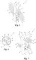
- Fig. 3 shows an example of a shaped piece 12.
- the connector 1 comprises such a shaped piece 12 for each blind hole 11, which can be removably inserted into the blind hole 11.
- the shaped pieces 12 are usually made of a different material than the fittings 4, 5, in particular of a plastic (optionally fiber-reinforced) or metal, preferably steel or aluminum. Even if shaped pieces 12 could be made of wood in individual cases, they are always separate from the fittings 4, 5.
- Each fitting 12 has a base surface 13, a cover surface 14 parallel thereto and a lateral surface 15 connecting the base and cover surfaces 13, 14, which is essentially generally cylindrical; "essentially” generally cylindrical because each fitting 12 has an oblique bore 16 for a mounting screw 17 ( Fig. 4 ) which penetrates the fitting 12 at an acute angle ⁇ to its base and cover surfaces 13, 14, which is why the cover and shell surfaces 14, 15 have an optional bevel 18 transverse to the inclined bore 16 for better engagement of a head of the assembly screw 17.
- the acute angle ⁇ is between 15 and 60 degrees depending on the requirements and material of the components 2, 3; in most cases it is between 25 and 50 degrees, for the fitting 12 the Fig. 3 at about 45° ( Fig. 4 ).
- the blind holes 11 optionally have a depth that corresponds to or is greater than the thickness D of the shaped pieces 12 from their respective base to their cover surfaces 13, 14.
- the shaped piece 12 shown has a round base 13; other shapes, e.g. oval, kidney-shaped or polygonal, are also possible.
- the blind holes 11 are not only adapted to the thickness D, but also to the shapes of the shaped pieces 12, in particular the shapes of their bases 13, so that each shaped piece 12 is positively received in the blind hole 11.
- the blind hole 11 can have a recess 20 in an area facing away from the end face 8 of its fitting 4, 5 to facilitate screwing in the assembly screw 17.
- each blind hole 11 is made by two overlapping blind holes, so that it has an approximately 8-shaped cross-section, in the part of which facing the front side 8 (here: upper) the shaped piece 12 with its Fig. 3 round base area 13 and in whose other (here: lower) part the recess 20 remains.
- the fittings 4, 5 (here: the fitting 4) have holes 21, which are inclined from the blind hole 11 towards the front side 8 and the penetrate the mounting side 6.
- These inclined bores 21 are arranged and aligned in the blind holes 11 in such a way that when inserting a fitting 12, its inclined bore 16 can be aligned with the inclined bore 21, ie the inclined bore 16 and the inclined bore 21 run at the same acute angle ⁇ , so that the mounting screw 17 can be rotated straight and unhindered through the fitting 12 and the inclined bore 21 into the component 2, 3.
- each fitting 4, 5 has at least one - in the example of the Fig. 2b and 4 : two straight bores 22, orthogonal to the mounting side 6, each for a tension screw 23, which are adjacent to, i.e. close to, the front side 8 of the fitting 4, 5 and penetrate the fitting 4, 5. With the tension screws 23, the fitting 4, 5 is fixed to the respective component 2, 3, for example, before screwing in the mounting screws 17.
- the fitting 4, 5 can be glued to the respective component on its mounting side 6.
- each fitting 4, 5 can have a front bore 24 on its end face 8, which is set in the center of the end face 8 in the fitting 4, 5, orthogonal to the end face.
- the front bore 24 can in particular be a blind bore.
- a pin 25, for example, can be inserted into the optional front bore 24, so that the two fittings 4, 5 are centered when hooked into one another and are then locked in the longitudinal direction of the end face 8 by the pin 25.
- FIG. 5 An alternative to this is shown Fig. 5 , in which the pin 25 of the example of the Fig. 4 is characterized by a (in Fig. 5 not visible, as it is countersunk) screw is replaced, which is screwed into the front hole 24.
- the front hole 24 penetrates the Fig. 5 upper fitting 5 from top to bottom.
- a pin 25 could also be inserted into the front hole 24 in this example.
- the contact sides 7 of the fittings 4, 5 can optionally be glued to the other component 3, 2.
- Figs. 6 and 7 show a further embodiment of the connector 1, in which each fitting 12 is penetrated by at least two (here: exactly two) further bores 26 flanking the oblique bore 16 and penetrating the fitting 12 approximately orthogonally to the base and cover surfaces 13, 14, each for a further screw 27.
- Fig. 7 shows the interlocking position of the two fittings 4, 5 - for better visibility without the components 2, 3.
- the acute angle ⁇ in this case is approximately 30°.
Landscapes
- Engineering & Computer Science (AREA)
- Architecture (AREA)
- General Engineering & Computer Science (AREA)
- Physics & Mathematics (AREA)
- Electromagnetism (AREA)
- Civil Engineering (AREA)
- Structural Engineering (AREA)
- Mechanical Engineering (AREA)
- Connection Of Plates (AREA)
Claims (15)
- Connecteur pour deux composants (2, 3), notamment des composants en bois, comprenant deux ferrures (4, 5) dont chacune possède un côté de montage (6) pour le montage sur respectivement l'un des composants (2, 3) et un côté de contact (7), situé en face du côté de montage (6), pour le contact avec respectivement l'autre des composants (3, 2), où les deux ferrures (4, 5) peuvent être accroché l'une dans l'autre sur un côté frontal (8) reliant le côté de montage et le côté de contact (6, 7), à cet effet, le côté frontal (8) possède sur toute sa longueur (L) s'étendant le long du côté de contact (7) un épaulement (10) affleurant avec le côté de contact (7) dont la largeur (B) dans la direction orthogonale (RN) par rapport au côté de contact (7) correspond essentiellement à la demie largeur (w) du côté frontal (8),
caractérisé en ce que les ferrures (4, 5) sont en bois, de préférence en contreplaqué, ou en un matériau composite bois-plastique et chaque ferrure (4, 5) possède sur son côté de contact (7) un ou plusieurs trous borgnes (11) de forme généralement cylindrique, le connecteur (1) comprenant en outre une pièce de forme (12) pour chaque trou borgne (11) permettant une insertion amovible dans le trou borgne (11), ladite pièce de forme possède une surface de base (13), une surface de couverture (14) parallèle à celle-ci, une surface d'enveloppe (15) essentiellement généralement cylindrique reliant ces deux surfaces et un alésage oblique (16) pour une vis de montage (17), ledit alésage oblique traversant la pièce de forme (12) sous un angle (α) aigu par rapport aux surfaces de base et de couverture (13, 14). - Connecteur selon la revendication 1, caractérisé en ce que chaque pièce de forme (12) est en métal, de préférence en acier.
- Connecteur selon la revendication 1 ou 2, caractérisé en ce que chacun des trous borgnes (11) de chaque ferrure (4, 5) a une distance minimale (δ) de 2 cm, de préférence entre 4 et 6,5 cm, de la périphérie de son côté de contact (7).
- Connecteur selon l'une des revendications 1 à 3, caractérisé en ce qu'à partir de chacun des trous borgnes (11) de chaque ferrure (4, 5) part un alésage (21) incliné en direction dudit côté frontal (8) de la ferrure (4, 5), traversant le côté de montage (6), lequel est disposé et orienté de telle manière que, lors de la mise en place d'une pièce de forme (12), son alésage oblique (16) peut être mis en alignement avec celui-ci.
- Connecteur selon l'une des revendications 1 à 4, caractérisé en ce que ledit angle aigu (α) se situe entre 15° et 60°, de préférence entre 25° et 50°.
- Connecteur selon l'une des revendications 1 à 5, caractérisé en ce que chaque ferrure (4, 5) a au moins deux trous borgnes (11), les trous borgnes (11) étant disposés symétriquement en miroir par rapport à un axe (A) du côté de contact (7) orthogonal par rapport audit côté frontal (8) et bissectant celui-ci.
- Connecteur selon l'une des revendications 1 à 6, caractérisé en ce chaque ferrure (4, 5) a, sur ledit côté frontal (8), un alésage frontal (24) central qui est orthogonal par rapport au côté frontal(8) et dans lequel on peut insérer une goupille (25) ou une vis.
- Connecteur selon la revendication 7, caractérisé en ce qu'au moins une des ferrures (4, 5) est traversée complètement par ledit alésage frontal (24).
- Connecteur selon l'une des revendications 1 à 8, caractérisé en ce qu'avec une hauteur du épaulement (10) augmentant sur le côté frontal (8) de chaque ferrure (4, 5), sa largeur diminue et, à mi-hauteur (h), correspond à la demie largeur (w) du coté frontal (8).
- Connecteur selon l'une des revendications 1 à 9, caractérisé en ce que l'alésage oblique (16) de chaque pièce de forme (12) traverse sa surface de base (13) sans toucher le bord (19) entre les surfaces de base et d'enveloppe (13, 15).
- Connecteur selon l'une des revendications 1 à 10, caractérisé en ce que les trous borgnes (11) ont une profondeur qui correspond à l'épaisseur (D) des pièces de forme (12) à partir de leur surface de base jusqu'à leur surface de couverture (13, 14).
- Connecteur selon l'une des revendications 1 à 11, caractérisé en ce que chaque pièce de forme (12) peut être logée dans le trou borgne (11) par complémentarité des formes et le trou borgne (11) a un évidement (20) au niveau d'une zone opposée audit côté frontal (8) pour le vissage d'une vis de montage (17).
- Connecteur selon l'une des revendications 1 à 12, caractérisé en ce que la surface de base (13) de chaque pièce de forme (12) est ronde.
- Connecteur selon l'une des revendications 1 à 13, caractérisé en ce que chaque ferrure (4, 5) est traversée par au moins un alésage rectiligne (22) pour une vis de tension (23), ledit alésage rectiligne étant orthogonal par rapport au côté de montage (6) et adjacent audit côté frontal (8).
- Connecteur selon l'une des revendications 1 à 12, caractérisé par au moins deux autres alésages (26), chacun pour une autre vis (27), lesdits autres alésages flanquant l'alésage oblique (16) de chaque pièce de forme (12) et traversant à peu près de manière orthogonale la pièce de forme (12) par rapport aux surfaces de base et de couverture (13, 14).
Priority Applications (2)
| Application Number | Priority Date | Filing Date | Title |
|---|---|---|---|
| EP22184024.2A EP4306811B1 (fr) | 2022-07-11 | 2022-07-11 | Dispositif de liaison pour deux composants, en particulier composants en bois |
| US18/218,332 US12392125B2 (en) | 2022-07-11 | 2023-07-05 | Connector for two components |
Applications Claiming Priority (1)
| Application Number | Priority Date | Filing Date | Title |
|---|---|---|---|
| EP22184024.2A EP4306811B1 (fr) | 2022-07-11 | 2022-07-11 | Dispositif de liaison pour deux composants, en particulier composants en bois |
Publications (3)
| Publication Number | Publication Date |
|---|---|
| EP4306811A1 EP4306811A1 (fr) | 2024-01-17 |
| EP4306811B1 true EP4306811B1 (fr) | 2025-03-19 |
| EP4306811C0 EP4306811C0 (fr) | 2025-03-19 |
Family
ID=82595217
Family Applications (1)
| Application Number | Title | Priority Date | Filing Date |
|---|---|---|---|
| EP22184024.2A Active EP4306811B1 (fr) | 2022-07-11 | 2022-07-11 | Dispositif de liaison pour deux composants, en particulier composants en bois |
Country Status (2)
| Country | Link |
|---|---|
| US (1) | US12392125B2 (fr) |
| EP (1) | EP4306811B1 (fr) |
Families Citing this family (2)
| Publication number | Priority date | Publication date | Assignee | Title |
|---|---|---|---|---|
| EP4080068B1 (fr) * | 2021-04-23 | 2025-08-20 | Knapp GmbH | Connecteur pour deux composants |
| US12516690B2 (en) * | 2024-02-08 | 2026-01-06 | My-Ti-Con Timber Connectors Inc. | Beam connector, connector member thereof, drill jig therefor, and beam assembly comprising the same |
Family Cites Families (11)
| Publication number | Priority date | Publication date | Assignee | Title |
|---|---|---|---|---|
| US3819198A (en) * | 1973-04-23 | 1974-06-25 | H Groves | Segmented ski apparatus including antivibration coupling means |
| US4646497A (en) * | 1985-03-21 | 1987-03-03 | Hoenle Egon R | Panel coupling |
| JPH0211822A (ja) * | 1988-06-29 | 1990-01-16 | Isuzu Motors Ltd | 回転電機付ターボチャージャの駆動装置 |
| US5913781A (en) * | 1996-05-31 | 1999-06-22 | Hanover Catalog Holdings, Inc. | Landscape timber connecting system |
| DE102005014900A1 (de) * | 2005-04-01 | 2006-10-05 | Induo Gesellschaft Zur Verwertung Von Schutzrechten Mbh & Co Kg | Verbundanker zum Verbinden mindestens zweier Bauelemente und System von miteinander verbundenen Bauelementen |
| JP4546915B2 (ja) * | 2005-11-14 | 2010-09-22 | 有限会社グランドフォーム | 木造建築用連結金物 |
| DE102008010612A1 (de) * | 2008-02-22 | 2009-09-03 | Kratzer, Daniel | Verbindungskörper |
| US8322942B2 (en) * | 2008-08-05 | 2012-12-04 | Howlett Enterprises, Llc | Interlocking connector system |
| EP3526418B1 (fr) * | 2016-10-14 | 2021-12-01 | Arcelormittal | Colonne en béton armé |
| EP3375946A1 (fr) * | 2017-03-17 | 2018-09-19 | Knapp GmbH | Élément d'assemblage par vissage oblique de deux pièces |
| EP3985189B1 (fr) | 2020-10-14 | 2023-12-06 | Knapp GmbH | Connecteur pour deux pièces |
-
2022
- 2022-07-11 EP EP22184024.2A patent/EP4306811B1/fr active Active
-
2023
- 2023-07-05 US US18/218,332 patent/US12392125B2/en active Active
Also Published As
| Publication number | Publication date |
|---|---|
| EP4306811A1 (fr) | 2024-01-17 |
| US12392125B2 (en) | 2025-08-19 |
| EP4306811C0 (fr) | 2025-03-19 |
| US20240011278A1 (en) | 2024-01-11 |
Similar Documents
| Publication | Publication Date | Title |
|---|---|---|
| EP3366855B1 (fr) | Élément de liaison, support et dispositif d'accouplement de composants verticaux | |
| EP3456892B1 (fr) | Connecteur pour deux pièces à assembler | |
| EP4306811B1 (fr) | Dispositif de liaison pour deux composants, en particulier composants en bois | |
| EP3433440B1 (fr) | Procédé d'assemblage de poutres en bois | |
| EP3985189B1 (fr) | Connecteur pour deux pièces | |
| DE102015103751A1 (de) | Stahlbetonbauteil | |
| EP3781755B1 (fr) | Dispositif d'accouplement pour la construction modulaire de bâtiments ou d'objets | |
| EP1216332B1 (fr) | Systeme de liaison destine a la fixation rigide d'au moins deux elements | |
| DE202018002529U1 (de) | Konstruktionsprofil | |
| EP4083343B1 (fr) | Élément de fixation | |
| DE202021004442U1 (de) | Wand-, Decken- oder Dachelementverbindung | |
| DE102012211638A1 (de) | Verankerungssystem | |
| EP2954124B1 (fr) | Construction à barres en bois comportant une première barre porteuse et au moins une deuxième barre porteuse reliées à force l'une à l'autre au niveau d'un noeud | |
| DE10349791B4 (de) | Pfosten-Riegel-Verbindung zwischen einem Pfosten und wenigstens einem an einer Pfostenseite stirnseitig anschließenden Riegel aus Holz oder Holzwerkstoff | |
| DE202011108692U1 (de) | Hohlprofil und Hallengerüst mit einem solchen Profil | |
| AT506192B1 (de) | Verbindungselement | |
| EP3339528B1 (fr) | Raccordement béton-bois et dispositif de fixation | |
| EP1878859A2 (fr) | Elément de liaison pour traverses et piquets de clôtures | |
| EP3263788B1 (fr) | Liaison de deux poutres en bois | |
| EP3322860B1 (fr) | Patte pour le transfert de charge dans l'isolation d'un bâtiment | |
| EP3375947B1 (fr) | Élément d'assemblage par vissage oblique de deux pièces | |
| EP4678837A1 (fr) | Liaison d'élément de paroi, de plafond, de façade ou de toit | |
| DE202004004073U1 (de) | Holzbauverbindung, insbesondere für Fertighäuser | |
| DE102009008765B4 (de) | Beschlagelement | |
| EP1744066B1 (fr) | Cadre aussi bien que des tiges pour un cadre |
Legal Events
| Date | Code | Title | Description |
|---|---|---|---|
| PUAI | Public reference made under article 153(3) epc to a published international application that has entered the european phase |
Free format text: ORIGINAL CODE: 0009012 |
|
| STAA | Information on the status of an ep patent application or granted ep patent |
Free format text: STATUS: THE APPLICATION HAS BEEN PUBLISHED |
|
| AK | Designated contracting states |
Kind code of ref document: A1 Designated state(s): AL AT BE BG CH CY CZ DE DK EE ES FI FR GB GR HR HU IE IS IT LI LT LU LV MC MK MT NL NO PL PT RO RS SE SI SK SM TR |
|
| STAA | Information on the status of an ep patent application or granted ep patent |
Free format text: STATUS: REQUEST FOR EXAMINATION WAS MADE |
|
| 17P | Request for examination filed |
Effective date: 20240613 |
|
| RBV | Designated contracting states (corrected) |
Designated state(s): AL AT BE BG CH CY CZ DE DK EE ES FI FR GB GR HR HU IE IS IT LI LT LU LV MC MK MT NL NO PL PT RO RS SE SI SK SM TR |
|
| GRAP | Despatch of communication of intention to grant a patent |
Free format text: ORIGINAL CODE: EPIDOSNIGR1 |
|
| STAA | Information on the status of an ep patent application or granted ep patent |
Free format text: STATUS: GRANT OF PATENT IS INTENDED |
|
| RIC1 | Information provided on ipc code assigned before grant |
Ipc: E04B 1/26 20060101ALI20241001BHEP Ipc: F16B 43/02 20060101ALI20241001BHEP Ipc: F16B 7/22 20060101AFI20241001BHEP |
|
| INTG | Intention to grant announced |
Effective date: 20241014 |
|
| GRAS | Grant fee paid |
Free format text: ORIGINAL CODE: EPIDOSNIGR3 |
|
| GRAA | (expected) grant |
Free format text: ORIGINAL CODE: 0009210 |
|
| STAA | Information on the status of an ep patent application or granted ep patent |
Free format text: STATUS: THE PATENT HAS BEEN GRANTED |
|
| AK | Designated contracting states |
Kind code of ref document: B1 Designated state(s): AL AT BE BG CH CY CZ DE DK EE ES FI FR GB GR HR HU IE IS IT LI LT LU LV MC MK MT NL NO PL PT RO RS SE SI SK SM TR |
|
| REG | Reference to a national code |
Ref country code: GB Ref legal event code: FG4D Free format text: NOT ENGLISH |
|
| REG | Reference to a national code |
Ref country code: CH Ref legal event code: EP |
|
| REG | Reference to a national code |
Ref country code: DE Ref legal event code: R096 Ref document number: 502022003229 Country of ref document: DE |
|
| REG | Reference to a national code |
Ref country code: IE Ref legal event code: FG4D Free format text: LANGUAGE OF EP DOCUMENT: GERMAN |
|
| U01 | Request for unitary effect filed |
Effective date: 20250328 |
|
| U07 | Unitary effect registered |
Designated state(s): AT BE BG DE DK EE FI FR IT LT LU LV MT NL PT RO SE SI Effective date: 20250403 |
|
| PG25 | Lapsed in a contracting state [announced via postgrant information from national office to epo] |
Ref country code: RS Free format text: LAPSE BECAUSE OF FAILURE TO SUBMIT A TRANSLATION OF THE DESCRIPTION OR TO PAY THE FEE WITHIN THE PRESCRIBED TIME-LIMIT Effective date: 20250619 |
|
| PG25 | Lapsed in a contracting state [announced via postgrant information from national office to epo] |
Ref country code: NO Free format text: LAPSE BECAUSE OF FAILURE TO SUBMIT A TRANSLATION OF THE DESCRIPTION OR TO PAY THE FEE WITHIN THE PRESCRIBED TIME-LIMIT Effective date: 20250619 |
|
| PG25 | Lapsed in a contracting state [announced via postgrant information from national office to epo] |
Ref country code: HR Free format text: LAPSE BECAUSE OF FAILURE TO SUBMIT A TRANSLATION OF THE DESCRIPTION OR TO PAY THE FEE WITHIN THE PRESCRIBED TIME-LIMIT Effective date: 20250319 |
|
| PG25 | Lapsed in a contracting state [announced via postgrant information from national office to epo] |
Ref country code: GR Free format text: LAPSE BECAUSE OF FAILURE TO SUBMIT A TRANSLATION OF THE DESCRIPTION OR TO PAY THE FEE WITHIN THE PRESCRIBED TIME-LIMIT Effective date: 20250620 |
|
| U20 | Renewal fee for the european patent with unitary effect paid |
Year of fee payment: 4 Effective date: 20250704 |
|
| PG25 | Lapsed in a contracting state [announced via postgrant information from national office to epo] |
Ref country code: SM Free format text: LAPSE BECAUSE OF FAILURE TO SUBMIT A TRANSLATION OF THE DESCRIPTION OR TO PAY THE FEE WITHIN THE PRESCRIBED TIME-LIMIT Effective date: 20250319 |
|
| PG25 | Lapsed in a contracting state [announced via postgrant information from national office to epo] |
Ref country code: ES Free format text: LAPSE BECAUSE OF FAILURE TO SUBMIT A TRANSLATION OF THE DESCRIPTION OR TO PAY THE FEE WITHIN THE PRESCRIBED TIME-LIMIT Effective date: 20250319 |
|
| PG25 | Lapsed in a contracting state [announced via postgrant information from national office to epo] |
Ref country code: PL Free format text: LAPSE BECAUSE OF FAILURE TO SUBMIT A TRANSLATION OF THE DESCRIPTION OR TO PAY THE FEE WITHIN THE PRESCRIBED TIME-LIMIT Effective date: 20250319 |
|
| PG25 | Lapsed in a contracting state [announced via postgrant information from national office to epo] |
Ref country code: CZ Free format text: LAPSE BECAUSE OF FAILURE TO SUBMIT A TRANSLATION OF THE DESCRIPTION OR TO PAY THE FEE WITHIN THE PRESCRIBED TIME-LIMIT Effective date: 20250319 |
|
| PG25 | Lapsed in a contracting state [announced via postgrant information from national office to epo] |
Ref country code: SK Free format text: LAPSE BECAUSE OF FAILURE TO SUBMIT A TRANSLATION OF THE DESCRIPTION OR TO PAY THE FEE WITHIN THE PRESCRIBED TIME-LIMIT Effective date: 20250319 |
|
| PG25 | Lapsed in a contracting state [announced via postgrant information from national office to epo] |
Ref country code: IS Free format text: LAPSE BECAUSE OF FAILURE TO SUBMIT A TRANSLATION OF THE DESCRIPTION OR TO PAY THE FEE WITHIN THE PRESCRIBED TIME-LIMIT Effective date: 20250719 |
|
| PLBE | No opposition filed within time limit |
Free format text: ORIGINAL CODE: 0009261 |
|
| STAA | Information on the status of an ep patent application or granted ep patent |
Free format text: STATUS: NO OPPOSITION FILED WITHIN TIME LIMIT |
|
| REG | Reference to a national code |
Ref country code: CH Ref legal event code: L10 Free format text: ST27 STATUS EVENT CODE: U-0-0-L10-L00 (AS PROVIDED BY THE NATIONAL OFFICE) Effective date: 20260128 |
|
| REG | Reference to a national code |
Ref country code: CH Ref legal event code: H13 Free format text: ST27 STATUS EVENT CODE: U-0-0-H10-H13 (AS PROVIDED BY THE NATIONAL OFFICE) Effective date: 20260224 |
|
| 26N | No opposition filed |
Effective date: 20251222 |
|
| PG25 | Lapsed in a contracting state [announced via postgrant information from national office to epo] |
Ref country code: CH Free format text: LAPSE BECAUSE OF NON-PAYMENT OF DUE FEES Effective date: 20250731 |