EP4310388A2 - Füllstation zum versorgen einer vielzahl von fahrzeugen mit einem wasserstoffhaltigen gas - Google Patents
Füllstation zum versorgen einer vielzahl von fahrzeugen mit einem wasserstoffhaltigen gas Download PDFInfo
- Publication number
- EP4310388A2 EP4310388A2 EP23215132.4A EP23215132A EP4310388A2 EP 4310388 A2 EP4310388 A2 EP 4310388A2 EP 23215132 A EP23215132 A EP 23215132A EP 4310388 A2 EP4310388 A2 EP 4310388A2
- Authority
- EP
- European Patent Office
- Prior art keywords
- block
- gas
- storage
- compression
- filling station
- Prior art date
- Legal status (The legal status is an assumption and is not a legal conclusion. Google has not performed a legal analysis and makes no representation as to the accuracy of the status listed.)
- Granted
Links
Images


Classifications
-
- F—MECHANICAL ENGINEERING; LIGHTING; HEATING; WEAPONS; BLASTING
- F17—STORING OR DISTRIBUTING GASES OR LIQUIDS
- F17C—VESSELS FOR CONTAINING OR STORING COMPRESSED, LIQUEFIED OR SOLIDIFIED GASES; FIXED-CAPACITY GAS-HOLDERS; FILLING VESSELS WITH, OR DISCHARGING FROM VESSELS, COMPRESSED, LIQUEFIED, OR SOLIDIFIED GASES
- F17C5/00—Methods or apparatus for filling containers with liquefied, solidified, or compressed gases under pressures
- F17C5/06—Methods or apparatus for filling containers with liquefied, solidified, or compressed gases under pressures for filling with compressed gases
-
- C—CHEMISTRY; METALLURGY
- C25—ELECTROLYTIC OR ELECTROPHORETIC PROCESSES; APPARATUS THEREFOR
- C25B—ELECTROLYTIC OR ELECTROPHORETIC PROCESSES FOR THE PRODUCTION OF COMPOUNDS OR NON-METALS; APPARATUS THEREFOR
- C25B1/00—Electrolytic production of inorganic compounds or non-metals
- C25B1/01—Products
- C25B1/02—Hydrogen or oxygen
- C25B1/04—Hydrogen or oxygen by electrolysis of water
-
- C—CHEMISTRY; METALLURGY
- C25—ELECTROLYTIC OR ELECTROPHORETIC PROCESSES; APPARATUS THEREFOR
- C25B—ELECTROLYTIC OR ELECTROPHORETIC PROCESSES FOR THE PRODUCTION OF COMPOUNDS OR NON-METALS; APPARATUS THEREFOR
- C25B9/00—Cells or assemblies of cells; Constructional parts of cells; Assemblies of constructional parts, e.g. electrode-diaphragm assemblies; Process-related cell features
- C25B9/17—Cells comprising dimensionally-stable non-movable electrodes; Assemblies of constructional parts thereof
-
- F—MECHANICAL ENGINEERING; LIGHTING; HEATING; WEAPONS; BLASTING
- F17—STORING OR DISTRIBUTING GASES OR LIQUIDS
- F17C—VESSELS FOR CONTAINING OR STORING COMPRESSED, LIQUEFIED OR SOLIDIFIED GASES; FIXED-CAPACITY GAS-HOLDERS; FILLING VESSELS WITH, OR DISCHARGING FROM VESSELS, COMPRESSED, LIQUEFIED, OR SOLIDIFIED GASES
- F17C2201/00—Vessel construction, in particular geometry, arrangement or size
- F17C2201/05—Size
- F17C2201/054—Size medium (>1 m3)
-
- F—MECHANICAL ENGINEERING; LIGHTING; HEATING; WEAPONS; BLASTING
- F17—STORING OR DISTRIBUTING GASES OR LIQUIDS
- F17C—VESSELS FOR CONTAINING OR STORING COMPRESSED, LIQUEFIED OR SOLIDIFIED GASES; FIXED-CAPACITY GAS-HOLDERS; FILLING VESSELS WITH, OR DISCHARGING FROM VESSELS, COMPRESSED, LIQUEFIED, OR SOLIDIFIED GASES
- F17C2201/00—Vessel construction, in particular geometry, arrangement or size
- F17C2201/05—Size
- F17C2201/056—Small (<1 m3)
-
- F—MECHANICAL ENGINEERING; LIGHTING; HEATING; WEAPONS; BLASTING
- F17—STORING OR DISTRIBUTING GASES OR LIQUIDS
- F17C—VESSELS FOR CONTAINING OR STORING COMPRESSED, LIQUEFIED OR SOLIDIFIED GASES; FIXED-CAPACITY GAS-HOLDERS; FILLING VESSELS WITH, OR DISCHARGING FROM VESSELS, COMPRESSED, LIQUEFIED, OR SOLIDIFIED GASES
- F17C2201/00—Vessel construction, in particular geometry, arrangement or size
- F17C2201/05—Size
- F17C2201/058—Size portable (<30 l)
-
- F—MECHANICAL ENGINEERING; LIGHTING; HEATING; WEAPONS; BLASTING
- F17—STORING OR DISTRIBUTING GASES OR LIQUIDS
- F17C—VESSELS FOR CONTAINING OR STORING COMPRESSED, LIQUEFIED OR SOLIDIFIED GASES; FIXED-CAPACITY GAS-HOLDERS; FILLING VESSELS WITH, OR DISCHARGING FROM VESSELS, COMPRESSED, LIQUEFIED, OR SOLIDIFIED GASES
- F17C2205/00—Vessel construction, in particular mounting arrangements, attachments or identifications means
- F17C2205/01—Mounting arrangements
- F17C2205/0123—Mounting arrangements characterised by number of vessels
- F17C2205/013—Two or more vessels
- F17C2205/0134—Two or more vessels characterised by the presence of fluid connection between vessels
-
- F—MECHANICAL ENGINEERING; LIGHTING; HEATING; WEAPONS; BLASTING
- F17—STORING OR DISTRIBUTING GASES OR LIQUIDS
- F17C—VESSELS FOR CONTAINING OR STORING COMPRESSED, LIQUEFIED OR SOLIDIFIED GASES; FIXED-CAPACITY GAS-HOLDERS; FILLING VESSELS WITH, OR DISCHARGING FROM VESSELS, COMPRESSED, LIQUEFIED, OR SOLIDIFIED GASES
- F17C2205/00—Vessel construction, in particular mounting arrangements, attachments or identifications means
- F17C2205/01—Mounting arrangements
- F17C2205/0123—Mounting arrangements characterised by number of vessels
- F17C2205/013—Two or more vessels
- F17C2205/0134—Two or more vessels characterised by the presence of fluid connection between vessels
- F17C2205/0146—Two or more vessels characterised by the presence of fluid connection between vessels with details of the manifold
-
- F—MECHANICAL ENGINEERING; LIGHTING; HEATING; WEAPONS; BLASTING
- F17—STORING OR DISTRIBUTING GASES OR LIQUIDS
- F17C—VESSELS FOR CONTAINING OR STORING COMPRESSED, LIQUEFIED OR SOLIDIFIED GASES; FIXED-CAPACITY GAS-HOLDERS; FILLING VESSELS WITH, OR DISCHARGING FROM VESSELS, COMPRESSED, LIQUEFIED, OR SOLIDIFIED GASES
- F17C2205/00—Vessel construction, in particular mounting arrangements, attachments or identifications means
- F17C2205/03—Fluid connections, filters, valves, closure means or other attachments
- F17C2205/0302—Fittings, valves, filters, or components in connection with the gas storage device
- F17C2205/0352—Pipes
-
- F—MECHANICAL ENGINEERING; LIGHTING; HEATING; WEAPONS; BLASTING
- F17—STORING OR DISTRIBUTING GASES OR LIQUIDS
- F17C—VESSELS FOR CONTAINING OR STORING COMPRESSED, LIQUEFIED OR SOLIDIFIED GASES; FIXED-CAPACITY GAS-HOLDERS; FILLING VESSELS WITH, OR DISCHARGING FROM VESSELS, COMPRESSED, LIQUEFIED, OR SOLIDIFIED GASES
- F17C2205/00—Vessel construction, in particular mounting arrangements, attachments or identifications means
- F17C2205/03—Fluid connections, filters, valves, closure means or other attachments
- F17C2205/0302—Fittings, valves, filters, or components in connection with the gas storage device
- F17C2205/0376—Dispensing pistols
-
- F—MECHANICAL ENGINEERING; LIGHTING; HEATING; WEAPONS; BLASTING
- F17—STORING OR DISTRIBUTING GASES OR LIQUIDS
- F17C—VESSELS FOR CONTAINING OR STORING COMPRESSED, LIQUEFIED OR SOLIDIFIED GASES; FIXED-CAPACITY GAS-HOLDERS; FILLING VESSELS WITH, OR DISCHARGING FROM VESSELS, COMPRESSED, LIQUEFIED, OR SOLIDIFIED GASES
- F17C2221/00—Handled fluid, in particular type of fluid
- F17C2221/01—Pure fluids
- F17C2221/012—Hydrogen
-
- F—MECHANICAL ENGINEERING; LIGHTING; HEATING; WEAPONS; BLASTING
- F17—STORING OR DISTRIBUTING GASES OR LIQUIDS
- F17C—VESSELS FOR CONTAINING OR STORING COMPRESSED, LIQUEFIED OR SOLIDIFIED GASES; FIXED-CAPACITY GAS-HOLDERS; FILLING VESSELS WITH, OR DISCHARGING FROM VESSELS, COMPRESSED, LIQUEFIED, OR SOLIDIFIED GASES
- F17C2223/00—Handled fluid before transfer, i.e. state of fluid when stored in the vessel or before transfer from the vessel
- F17C2223/01—Handled fluid before transfer, i.e. state of fluid when stored in the vessel or before transfer from the vessel characterised by the phase
- F17C2223/0107—Single phase
- F17C2223/0123—Single phase gaseous, e.g. CNG, GNC
-
- F—MECHANICAL ENGINEERING; LIGHTING; HEATING; WEAPONS; BLASTING
- F17—STORING OR DISTRIBUTING GASES OR LIQUIDS
- F17C—VESSELS FOR CONTAINING OR STORING COMPRESSED, LIQUEFIED OR SOLIDIFIED GASES; FIXED-CAPACITY GAS-HOLDERS; FILLING VESSELS WITH, OR DISCHARGING FROM VESSELS, COMPRESSED, LIQUEFIED, OR SOLIDIFIED GASES
- F17C2223/00—Handled fluid before transfer, i.e. state of fluid when stored in the vessel or before transfer from the vessel
- F17C2223/03—Handled fluid before transfer, i.e. state of fluid when stored in the vessel or before transfer from the vessel characterised by the pressure level
- F17C2223/035—High pressure (>10 bar)
-
- F—MECHANICAL ENGINEERING; LIGHTING; HEATING; WEAPONS; BLASTING
- F17—STORING OR DISTRIBUTING GASES OR LIQUIDS
- F17C—VESSELS FOR CONTAINING OR STORING COMPRESSED, LIQUEFIED OR SOLIDIFIED GASES; FIXED-CAPACITY GAS-HOLDERS; FILLING VESSELS WITH, OR DISCHARGING FROM VESSELS, COMPRESSED, LIQUEFIED, OR SOLIDIFIED GASES
- F17C2223/00—Handled fluid before transfer, i.e. state of fluid when stored in the vessel or before transfer from the vessel
- F17C2223/03—Handled fluid before transfer, i.e. state of fluid when stored in the vessel or before transfer from the vessel characterised by the pressure level
- F17C2223/036—Very high pressure (>80 bar)
-
- F—MECHANICAL ENGINEERING; LIGHTING; HEATING; WEAPONS; BLASTING
- F17—STORING OR DISTRIBUTING GASES OR LIQUIDS
- F17C—VESSELS FOR CONTAINING OR STORING COMPRESSED, LIQUEFIED OR SOLIDIFIED GASES; FIXED-CAPACITY GAS-HOLDERS; FILLING VESSELS WITH, OR DISCHARGING FROM VESSELS, COMPRESSED, LIQUEFIED, OR SOLIDIFIED GASES
- F17C2225/00—Handled fluid after transfer, i.e. state of fluid after transfer from the vessel
- F17C2225/01—Handled fluid after transfer, i.e. state of fluid after transfer from the vessel characterised by the phase
- F17C2225/0107—Single phase
- F17C2225/0123—Single phase gaseous, e.g. CNG, GNC
-
- F—MECHANICAL ENGINEERING; LIGHTING; HEATING; WEAPONS; BLASTING
- F17—STORING OR DISTRIBUTING GASES OR LIQUIDS
- F17C—VESSELS FOR CONTAINING OR STORING COMPRESSED, LIQUEFIED OR SOLIDIFIED GASES; FIXED-CAPACITY GAS-HOLDERS; FILLING VESSELS WITH, OR DISCHARGING FROM VESSELS, COMPRESSED, LIQUEFIED, OR SOLIDIFIED GASES
- F17C2225/00—Handled fluid after transfer, i.e. state of fluid after transfer from the vessel
- F17C2225/03—Handled fluid after transfer, i.e. state of fluid after transfer from the vessel characterised by the pressure level
- F17C2225/036—Very high pressure, i.e. above 80 bars
-
- F—MECHANICAL ENGINEERING; LIGHTING; HEATING; WEAPONS; BLASTING
- F17—STORING OR DISTRIBUTING GASES OR LIQUIDS
- F17C—VESSELS FOR CONTAINING OR STORING COMPRESSED, LIQUEFIED OR SOLIDIFIED GASES; FIXED-CAPACITY GAS-HOLDERS; FILLING VESSELS WITH, OR DISCHARGING FROM VESSELS, COMPRESSED, LIQUEFIED, OR SOLIDIFIED GASES
- F17C2227/00—Transfer of fluids, i.e. method or means for transferring the fluid; Heat exchange with the fluid
- F17C2227/01—Propulsion of the fluid
- F17C2227/0128—Propulsion of the fluid with pumps or compressors
- F17C2227/0157—Compressors
-
- F—MECHANICAL ENGINEERING; LIGHTING; HEATING; WEAPONS; BLASTING
- F17—STORING OR DISTRIBUTING GASES OR LIQUIDS
- F17C—VESSELS FOR CONTAINING OR STORING COMPRESSED, LIQUEFIED OR SOLIDIFIED GASES; FIXED-CAPACITY GAS-HOLDERS; FILLING VESSELS WITH, OR DISCHARGING FROM VESSELS, COMPRESSED, LIQUEFIED, OR SOLIDIFIED GASES
- F17C2227/00—Transfer of fluids, i.e. method or means for transferring the fluid; Heat exchange with the fluid
- F17C2227/01—Propulsion of the fluid
- F17C2227/0128—Propulsion of the fluid with pumps or compressors
- F17C2227/0171—Arrangement
- F17C2227/0185—Arrangement comprising several pumps or compressors
-
- F—MECHANICAL ENGINEERING; LIGHTING; HEATING; WEAPONS; BLASTING
- F17—STORING OR DISTRIBUTING GASES OR LIQUIDS
- F17C—VESSELS FOR CONTAINING OR STORING COMPRESSED, LIQUEFIED OR SOLIDIFIED GASES; FIXED-CAPACITY GAS-HOLDERS; FILLING VESSELS WITH, OR DISCHARGING FROM VESSELS, COMPRESSED, LIQUEFIED, OR SOLIDIFIED GASES
- F17C2227/00—Transfer of fluids, i.e. method or means for transferring the fluid; Heat exchange with the fluid
- F17C2227/03—Heat exchange with the fluid
- F17C2227/0337—Heat exchange with the fluid by cooling
-
- F—MECHANICAL ENGINEERING; LIGHTING; HEATING; WEAPONS; BLASTING
- F17—STORING OR DISTRIBUTING GASES OR LIQUIDS
- F17C—VESSELS FOR CONTAINING OR STORING COMPRESSED, LIQUEFIED OR SOLIDIFIED GASES; FIXED-CAPACITY GAS-HOLDERS; FILLING VESSELS WITH, OR DISCHARGING FROM VESSELS, COMPRESSED, LIQUEFIED, OR SOLIDIFIED GASES
- F17C2227/00—Transfer of fluids, i.e. method or means for transferring the fluid; Heat exchange with the fluid
- F17C2227/03—Heat exchange with the fluid
- F17C2227/0337—Heat exchange with the fluid by cooling
- F17C2227/0341—Heat exchange with the fluid by cooling using another fluid
- F17C2227/0353—Heat exchange with the fluid by cooling using another fluid using cryocooler
-
- F—MECHANICAL ENGINEERING; LIGHTING; HEATING; WEAPONS; BLASTING
- F17—STORING OR DISTRIBUTING GASES OR LIQUIDS
- F17C—VESSELS FOR CONTAINING OR STORING COMPRESSED, LIQUEFIED OR SOLIDIFIED GASES; FIXED-CAPACITY GAS-HOLDERS; FILLING VESSELS WITH, OR DISCHARGING FROM VESSELS, COMPRESSED, LIQUEFIED, OR SOLIDIFIED GASES
- F17C2227/00—Transfer of fluids, i.e. method or means for transferring the fluid; Heat exchange with the fluid
- F17C2227/03—Heat exchange with the fluid
- F17C2227/0337—Heat exchange with the fluid by cooling
- F17C2227/0341—Heat exchange with the fluid by cooling using another fluid
- F17C2227/0355—Heat exchange with the fluid by cooling using another fluid in a closed loop
-
- F—MECHANICAL ENGINEERING; LIGHTING; HEATING; WEAPONS; BLASTING
- F17—STORING OR DISTRIBUTING GASES OR LIQUIDS
- F17C—VESSELS FOR CONTAINING OR STORING COMPRESSED, LIQUEFIED OR SOLIDIFIED GASES; FIXED-CAPACITY GAS-HOLDERS; FILLING VESSELS WITH, OR DISCHARGING FROM VESSELS, COMPRESSED, LIQUEFIED, OR SOLIDIFIED GASES
- F17C2227/00—Transfer of fluids, i.e. method or means for transferring the fluid; Heat exchange with the fluid
- F17C2227/03—Heat exchange with the fluid
- F17C2227/0367—Localisation of heat exchange
- F17C2227/0388—Localisation of heat exchange separate
-
- F—MECHANICAL ENGINEERING; LIGHTING; HEATING; WEAPONS; BLASTING
- F17—STORING OR DISTRIBUTING GASES OR LIQUIDS
- F17C—VESSELS FOR CONTAINING OR STORING COMPRESSED, LIQUEFIED OR SOLIDIFIED GASES; FIXED-CAPACITY GAS-HOLDERS; FILLING VESSELS WITH, OR DISCHARGING FROM VESSELS, COMPRESSED, LIQUEFIED, OR SOLIDIFIED GASES
- F17C2227/00—Transfer of fluids, i.e. method or means for transferring the fluid; Heat exchange with the fluid
- F17C2227/04—Methods for emptying or filling
- F17C2227/043—Methods for emptying or filling by pressure cascade
-
- F—MECHANICAL ENGINEERING; LIGHTING; HEATING; WEAPONS; BLASTING
- F17—STORING OR DISTRIBUTING GASES OR LIQUIDS
- F17C—VESSELS FOR CONTAINING OR STORING COMPRESSED, LIQUEFIED OR SOLIDIFIED GASES; FIXED-CAPACITY GAS-HOLDERS; FILLING VESSELS WITH, OR DISCHARGING FROM VESSELS, COMPRESSED, LIQUEFIED, OR SOLIDIFIED GASES
- F17C2227/00—Transfer of fluids, i.e. method or means for transferring the fluid; Heat exchange with the fluid
- F17C2227/04—Methods for emptying or filling
- F17C2227/047—Methods for emptying or filling by repeating a process cycle
-
- F—MECHANICAL ENGINEERING; LIGHTING; HEATING; WEAPONS; BLASTING
- F17—STORING OR DISTRIBUTING GASES OR LIQUIDS
- F17C—VESSELS FOR CONTAINING OR STORING COMPRESSED, LIQUEFIED OR SOLIDIFIED GASES; FIXED-CAPACITY GAS-HOLDERS; FILLING VESSELS WITH, OR DISCHARGING FROM VESSELS, COMPRESSED, LIQUEFIED, OR SOLIDIFIED GASES
- F17C2250/00—Accessories; Control means; Indicating, measuring or monitoring of parameters
- F17C2250/03—Control means
- F17C2250/032—Control means using computers
-
- F—MECHANICAL ENGINEERING; LIGHTING; HEATING; WEAPONS; BLASTING
- F17—STORING OR DISTRIBUTING GASES OR LIQUIDS
- F17C—VESSELS FOR CONTAINING OR STORING COMPRESSED, LIQUEFIED OR SOLIDIFIED GASES; FIXED-CAPACITY GAS-HOLDERS; FILLING VESSELS WITH, OR DISCHARGING FROM VESSELS, COMPRESSED, LIQUEFIED, OR SOLIDIFIED GASES
- F17C2260/00—Purposes of gas storage and gas handling
- F17C2260/02—Improving properties related to fluid or fluid transfer
- F17C2260/023—Avoiding overheating
-
- F—MECHANICAL ENGINEERING; LIGHTING; HEATING; WEAPONS; BLASTING
- F17—STORING OR DISTRIBUTING GASES OR LIQUIDS
- F17C—VESSELS FOR CONTAINING OR STORING COMPRESSED, LIQUEFIED OR SOLIDIFIED GASES; FIXED-CAPACITY GAS-HOLDERS; FILLING VESSELS WITH, OR DISCHARGING FROM VESSELS, COMPRESSED, LIQUEFIED, OR SOLIDIFIED GASES
- F17C2260/00—Purposes of gas storage and gas handling
- F17C2260/02—Improving properties related to fluid or fluid transfer
- F17C2260/025—Reducing transfer time
-
- F—MECHANICAL ENGINEERING; LIGHTING; HEATING; WEAPONS; BLASTING
- F17—STORING OR DISTRIBUTING GASES OR LIQUIDS
- F17C—VESSELS FOR CONTAINING OR STORING COMPRESSED, LIQUEFIED OR SOLIDIFIED GASES; FIXED-CAPACITY GAS-HOLDERS; FILLING VESSELS WITH, OR DISCHARGING FROM VESSELS, COMPRESSED, LIQUEFIED, OR SOLIDIFIED GASES
- F17C2265/00—Effects achieved by gas storage or gas handling
- F17C2265/06—Fluid distribution
- F17C2265/061—Fluid distribution for supply of supplying vehicles
-
- F—MECHANICAL ENGINEERING; LIGHTING; HEATING; WEAPONS; BLASTING
- F17—STORING OR DISTRIBUTING GASES OR LIQUIDS
- F17C—VESSELS FOR CONTAINING OR STORING COMPRESSED, LIQUEFIED OR SOLIDIFIED GASES; FIXED-CAPACITY GAS-HOLDERS; FILLING VESSELS WITH, OR DISCHARGING FROM VESSELS, COMPRESSED, LIQUEFIED, OR SOLIDIFIED GASES
- F17C2265/00—Effects achieved by gas storage or gas handling
- F17C2265/06—Fluid distribution
- F17C2265/063—Fluid distribution for supply of refuelling stations
-
- F—MECHANICAL ENGINEERING; LIGHTING; HEATING; WEAPONS; BLASTING
- F17—STORING OR DISTRIBUTING GASES OR LIQUIDS
- F17C—VESSELS FOR CONTAINING OR STORING COMPRESSED, LIQUEFIED OR SOLIDIFIED GASES; FIXED-CAPACITY GAS-HOLDERS; FILLING VESSELS WITH, OR DISCHARGING FROM VESSELS, COMPRESSED, LIQUEFIED, OR SOLIDIFIED GASES
- F17C2265/00—Effects achieved by gas storage or gas handling
- F17C2265/06—Fluid distribution
- F17C2265/065—Fluid distribution for refuelling vehicle fuel tanks
-
- F—MECHANICAL ENGINEERING; LIGHTING; HEATING; WEAPONS; BLASTING
- F17—STORING OR DISTRIBUTING GASES OR LIQUIDS
- F17C—VESSELS FOR CONTAINING OR STORING COMPRESSED, LIQUEFIED OR SOLIDIFIED GASES; FIXED-CAPACITY GAS-HOLDERS; FILLING VESSELS WITH, OR DISCHARGING FROM VESSELS, COMPRESSED, LIQUEFIED, OR SOLIDIFIED GASES
- F17C2270/00—Applications
- F17C2270/01—Applications for fluid transport or storage
- F17C2270/0102—Applications for fluid transport or storage on or in the water
- F17C2270/0105—Ships
-
- F—MECHANICAL ENGINEERING; LIGHTING; HEATING; WEAPONS; BLASTING
- F17—STORING OR DISTRIBUTING GASES OR LIQUIDS
- F17C—VESSELS FOR CONTAINING OR STORING COMPRESSED, LIQUEFIED OR SOLIDIFIED GASES; FIXED-CAPACITY GAS-HOLDERS; FILLING VESSELS WITH, OR DISCHARGING FROM VESSELS, COMPRESSED, LIQUEFIED, OR SOLIDIFIED GASES
- F17C2270/00—Applications
- F17C2270/01—Applications for fluid transport or storage
- F17C2270/0165—Applications for fluid transport or storage on the road
- F17C2270/0168—Applications for fluid transport or storage on the road by vehicles
- F17C2270/0171—Trucks
-
- F—MECHANICAL ENGINEERING; LIGHTING; HEATING; WEAPONS; BLASTING
- F17—STORING OR DISTRIBUTING GASES OR LIQUIDS
- F17C—VESSELS FOR CONTAINING OR STORING COMPRESSED, LIQUEFIED OR SOLIDIFIED GASES; FIXED-CAPACITY GAS-HOLDERS; FILLING VESSELS WITH, OR DISCHARGING FROM VESSELS, COMPRESSED, LIQUEFIED, OR SOLIDIFIED GASES
- F17C2270/00—Applications
- F17C2270/01—Applications for fluid transport or storage
- F17C2270/0165—Applications for fluid transport or storage on the road
- F17C2270/0168—Applications for fluid transport or storage on the road by vehicles
- F17C2270/0173—Railways
-
- F—MECHANICAL ENGINEERING; LIGHTING; HEATING; WEAPONS; BLASTING
- F17—STORING OR DISTRIBUTING GASES OR LIQUIDS
- F17C—VESSELS FOR CONTAINING OR STORING COMPRESSED, LIQUEFIED OR SOLIDIFIED GASES; FIXED-CAPACITY GAS-HOLDERS; FILLING VESSELS WITH, OR DISCHARGING FROM VESSELS, COMPRESSED, LIQUEFIED, OR SOLIDIFIED GASES
- F17C2270/00—Applications
- F17C2270/01—Applications for fluid transport or storage
- F17C2270/0165—Applications for fluid transport or storage on the road
- F17C2270/0168—Applications for fluid transport or storage on the road by vehicles
- F17C2270/0176—Buses
-
- F—MECHANICAL ENGINEERING; LIGHTING; HEATING; WEAPONS; BLASTING
- F17—STORING OR DISTRIBUTING GASES OR LIQUIDS
- F17C—VESSELS FOR CONTAINING OR STORING COMPRESSED, LIQUEFIED OR SOLIDIFIED GASES; FIXED-CAPACITY GAS-HOLDERS; FILLING VESSELS WITH, OR DISCHARGING FROM VESSELS, COMPRESSED, LIQUEFIED, OR SOLIDIFIED GASES
- F17C2270/00—Applications
- F17C2270/01—Applications for fluid transport or storage
- F17C2270/0165—Applications for fluid transport or storage on the road
- F17C2270/0168—Applications for fluid transport or storage on the road by vehicles
- F17C2270/0178—Cars
-
- F—MECHANICAL ENGINEERING; LIGHTING; HEATING; WEAPONS; BLASTING
- F17—STORING OR DISTRIBUTING GASES OR LIQUIDS
- F17C—VESSELS FOR CONTAINING OR STORING COMPRESSED, LIQUEFIED OR SOLIDIFIED GASES; FIXED-CAPACITY GAS-HOLDERS; FILLING VESSELS WITH, OR DISCHARGING FROM VESSELS, COMPRESSED, LIQUEFIED, OR SOLIDIFIED GASES
- F17C2270/00—Applications
- F17C2270/01—Applications for fluid transport or storage
- F17C2270/0186—Applications for fluid transport or storage in the air or in space
-
- F—MECHANICAL ENGINEERING; LIGHTING; HEATING; WEAPONS; BLASTING
- F17—STORING OR DISTRIBUTING GASES OR LIQUIDS
- F17C—VESSELS FOR CONTAINING OR STORING COMPRESSED, LIQUEFIED OR SOLIDIFIED GASES; FIXED-CAPACITY GAS-HOLDERS; FILLING VESSELS WITH, OR DISCHARGING FROM VESSELS, COMPRESSED, LIQUEFIED, OR SOLIDIFIED GASES
- F17C2270/00—Applications
- F17C2270/01—Applications for fluid transport or storage
- F17C2270/0186—Applications for fluid transport or storage in the air or in space
- F17C2270/0192—Hot air balloons
-
- Y—GENERAL TAGGING OF NEW TECHNOLOGICAL DEVELOPMENTS; GENERAL TAGGING OF CROSS-SECTIONAL TECHNOLOGIES SPANNING OVER SEVERAL SECTIONS OF THE IPC; TECHNICAL SUBJECTS COVERED BY FORMER USPC CROSS-REFERENCE ART COLLECTIONS [XRACs] AND DIGESTS
- Y02—TECHNOLOGIES OR APPLICATIONS FOR MITIGATION OR ADAPTATION AGAINST CLIMATE CHANGE
- Y02E—REDUCTION OF GREENHOUSE GAS [GHG] EMISSIONS, RELATED TO ENERGY GENERATION, TRANSMISSION OR DISTRIBUTION
- Y02E60/00—Enabling technologies; Technologies with a potential or indirect contribution to GHG emissions mitigation
- Y02E60/30—Hydrogen technology
- Y02E60/32—Hydrogen storage
-
- Y—GENERAL TAGGING OF NEW TECHNOLOGICAL DEVELOPMENTS; GENERAL TAGGING OF CROSS-SECTIONAL TECHNOLOGIES SPANNING OVER SEVERAL SECTIONS OF THE IPC; TECHNICAL SUBJECTS COVERED BY FORMER USPC CROSS-REFERENCE ART COLLECTIONS [XRACs] AND DIGESTS
- Y02—TECHNOLOGIES OR APPLICATIONS FOR MITIGATION OR ADAPTATION AGAINST CLIMATE CHANGE
- Y02E—REDUCTION OF GREENHOUSE GAS [GHG] EMISSIONS, RELATED TO ENERGY GENERATION, TRANSMISSION OR DISTRIBUTION
- Y02E60/00—Enabling technologies; Technologies with a potential or indirect contribution to GHG emissions mitigation
- Y02E60/30—Hydrogen technology
- Y02E60/36—Hydrogen production from non-carbon containing sources, e.g. by water electrolysis
Definitions
- a filling station for fueling a plurality of vehicles with a hydrogen-containing gas is disclosed.
- the rapid filling of high pressure tanks on board hydrogen vehicles with gaseous hydrogen is conventionally carried out by successive pressure balancing between a plurality of high pressure containers.
- This cascade filling is obtained by carrying out a succession of pressure equalizations between, on the one hand, the vehicle tank and, on the other hand, containers of increasing pressure.
- the present invention aims to overcome at least in part the aforementioned drawbacks of the state of the art, by proposing a filling station architecture which is scalable, versatile, and adaptable to a wide variety of needs.
- a filling station according to the invention has the advantage, contrary to the state of the art, of presenting a plurality of components inside each block.
- the size of each block can easily be adapted to the scale of the station's needs by adding or removing components.
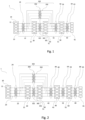
- THE figures 1 to 3 represent architectures of a filling station 1 conforming to the present invention.
- Such a filling station 1 is intended to supply a plurality of vehicles 61 with gas containing hydrogen from a source.
- the vehicles 61 may in particular be land vehicles such as cars, buses, trucks, trains, but also maritime vehicles such as ships or air vehicles such as airships.
- the gas may be pure dihydrogen, or a gas mixture comprising dihydrogen such as a natural gas-dihydrogen mixture for example, comprising at least 5% dihydrogen, and preferably at least 20% dihydrogen.
- a filling station 1 in accordance with the present invention may comprise a supply block 10 comprising at least one gas supply unit 11 and forming the source from which the gas comes.
- the source can be a hydrogen production unit, which can be fixed or mobile.
- the source can be an electrolyzer, making it possible to produce gaseous dihydrogen in situ by electrolysis of water.
- the electrolyser is a high capacity electrolyser, capable of generating from 10 to 1000 Nm3/h, to supply the filling station with gas at medium pressure.
- medium pressure gas we mean a gas having a pressure of between 50 mbar and 60 bar.
- the electrolyser supplies the filling station with gas having a pressure of between 10 and 30 bar, or even a pressure equal to 30 bar.
- the source may be a simple mobile gas storage unit, such as a mobile tank or cylinder.
- a tank can be placed on any means of transport such as a truck, a train or even a boat to transport gas from an external production source to the station.
- the mobile gas storage unit can then contain gas at medium or high pressure.
- high pressure gas we mean a gas having a pressure greater than 60 bar, for example 200, 350, 500 or 1000 bar.
- the supply block 10 comprises a plurality of gas supply units 11.
- a filling station according to the present invention can also be supplied in part by an external source of hydrogen production, via means of gas transport external to the station such as trailers (“trailers” according to the Anglo-Saxon expression frequently used) or a gas pipeline.
- the station filling may also not include a gas supply unit 11 and be supplied exclusively by such an external source.
- a filling station 1 comprises a storage block 30 comprising a plurality of containers 31 for storing the gas at high pressure.
- each container 31 of the storage block 30 is capable of storing gas at a pressure greater than 200 bar, preferably at a maximum pressure of 500 bar or even 1000 bar.
- Each container 31 can contain a volume of high pressure gas greater than 10 L, preferably between 5 and 50 m 3 .
- a container may consist of one or more storage bottles.
- the storage block 30 comprises at least four containers 31, or even at least five containers 31 or more.
- the presence of a plurality of containers 31 makes it possible in particular to carry out successive pressure balancing, for example to carry out cascade fillings as defined in the introduction.
- the filling station 1 further comprises a compression block 20 comprising a plurality of compressors 21 to increase the pressure of the gas destined for the storage block 30.
- Each compressor 21 typically makes it possible to increase the pressure of the gas from a pressure preferably between 10 and 30 bar to a pressure which can go up to 500 bar, or even up to 1000 bar, to supply a container 31 with gas at high pressure.
- the compression block 20 comprises at least four compressors 21, or even at least five compressors 21 or more.
- each block 20 and a storage block 30 each comprising four constituents, this number is in no way limiting. Each block can also contain a different number of constituents.
- the filling station also includes a storage circuit 321 for circulating the gas from the compression block 20 to the storage block 30.
- the storage circuit 321 comprises a network of storage conduits 331 connecting each compressor 21 of the compression block 20 to each container 31 of the storage block 30.
- the storage circuit 321 also includes at least one storage distributor 341 to selectively associate the compressors 21 and the containers 31.
- the storage distributor 341 can be a valve placed on a storage conduit 331 and making it possible to open or close the storage conduit 331.
- a valve can be placed on each storage conduit 331.
- the storage distributor 341 can be a valve with several positions, capable of operating any combination of opening and closing of each storage conduit 331.
- a filling station 1 further comprises control means for controlling the storage dispenser(s) 341.
- the control means can be configured to actuate the closing and/or opening of each storage conduit 331 of the network of storage conduits 331 either on the instruction of an operator, or according to preconfigured conditions.
- the control means may include a computer previously configured to carry out these operations.
- This calculator can be integrated into a control unit of station 1.
- the storage circuit 321 thus makes it possible to supply the plurality of containers 31 with high pressure gas, preferably of the order of 400 to 500 bar, or even 700 bar to 1000 bar.
- the storage distributors 341 make it possible to select at any time, according to predetermined conditions, the compressor(s) 21 used to supply a given container 31, as well as the container(s) 31 to be supplied with high pressure gas.
- a filling station 1 in accordance with the present invention also comprises a recharge circuit 322 for circulating the gas from the storage block 30 to the compression block 20.
- the recharge circuit 322 comprises a network of recharge conduits 332 connecting each container 31 of the storage block 30 to each compressor 21 of the storage block 30.
- the recharging circuit 322 further comprises at least one recharging distributor 342 for selectively associating the containers 31 and the compressors 21.
- the refill dispensers 342 may be similar to the storage dispensers 341 previously described.
- control means are also configured to control the refill dispenser(s) 342.
- the recharge circuit 322 thus makes it possible to carry out pressure consolidation, that is to say to circulate gas from a given container 31 towards one or more compressors 21, which then increases (s) the pressure of the gas received for resupply one or more containers 31 through the storage circuit 321.
- the refill distributors 342 make it possible to select at any time the containers 31 and the compressors 21 to be used to achieve pressure consolidation.
- a recharging station 1 in accordance with the invention makes it possible to reconfigure dynamically and as necessary the association of the compressors 21 of the compression block 20 with the containers 31 of the storage block 30.
- Redundancy means the fact of having several copies of the same equipment with the aim of increasing the total capacity or the performance of a system and /or reduce the risk of breakdown.
- Increasing redundancy helps improve the reliability of a station, but classically requires multiplying the number of each copy.
- a second identical component ensuring only redundancy.
- the possibility of reconfiguration offered by the invention allows several components to participate in the same mechanical solution, increasing redundancy.
- the same component can dynamically be allocated to one function or another, it is possible to increase the redundancy of the equipment constituting station 1 without doubling the number of components necessary to ensure this redundancy.
- a station 1 in accordance with the present invention thus has the advantage of having greater reliability than a station in which each component would have a dedicated functionality, each component of a block being able to be used in addition to or in replacement of another.
- the possibility of dynamic reconfiguration offered by such a station makes it possible to ensure the continuity of activity of the station even in the face of a need for maintenance. It can just as easily be preventive maintenance, i.e. a need to maintain a component before it is damaged, or curative maintenance, i.e. i.e. the failure of a component.
- control means of the corresponding block can reconfigure the corresponding circuit and control the distributors to compensate for the deficiency of the unavailable component by adjusting the operation of the other components of the block as necessary.
- a filling station 1 can also include containers 31 and compressors 21 not belonging to the blocks previously described.
- the station may comprise at least one other container, distinct from the plurality of containers 31 of the storage block 30, the other container not necessarily being fluidly connectable to all the other compressors 21 included in the station 1, and in particular to each compressor 21 of the plurality of compressors 21 of the compression block 20.
- the station 1 can comprise at least one other compressor 21, distinct from the plurality of compressors 21 of the compression block 20, the other compressor 21 not being fluidly connectable to all the other containers included in station 1, and in particular to each container 31 of the plurality of containers 31 of the storage block 30.
- the volume of the containers can be chosen freely, and is in no way limited to specific volumes.
- At least one other container can be provided to contain a smaller volume of gas than those mentioned previously, for example of the order of 1 L.
- Such volumes can in particular be used in the context of so-called filling methods.
- direct compression as opposed to cascade filling.
- gas generally coming from a container in the storage block or directly from the supply block 10, circulates to a compressor.
- the compressor increases the pressure of the gas and circulates it through the low volume container to the vehicle's tank to supply it. The tank is thus supplied as the compressor operates.
- Such a method has the advantage of not requiring a container capable of storing gas at pressures greater than 500 bar.
- the gas compressed by the compressor feeds directly the vehicle's tank by temporarily circulating through the low volume container, which aims to smooth the pressure level at the compressor outlet.
- a container can consist of one or more bottles, but it can also simply be a conduit of suitable diameter and length.
- This method also has the advantage compared to cascade filling of not creating, when filling the tank, heating in the tank by the effect of quasi-adiabatic expansion described in the remainder of the description.
- At least part of the compressors 21 of the compression block 20 is connected to the source.
- the filling station 1 also includes a compression circuit 22 for circulating the gas from the supply block 10 to the compression block 20.
- the compression circuit 22 comprises a network of compression conduits 23 connecting each gas supply unit 11 to each compressor 21 of the compression block 20.
- the compression circuit 22 further comprises at least one compression distributor 24 for selectively associating the gas supply units 11 with the compressors 21.
- the compression distributors 24 may be similar to the storage distributors 341 previously described.
- control means are also configured to control the compression distributor(s) 24.
- the filling station 1 also makes it possible to dynamically reconfigure, according to needs, the quantity of gas coming from the source to supply the storage block 30 via the compression block 20.
- a filling station 1 also comprises a power supply unit 50 comprising at least one feeder 51 intended to supply a vehicle 61 among the plurality of vehicles 61 to be supplied.
- feeder 51 means a means making it possible to regulate the rise in pressure of the tank of the vehicle 61, that is to say, to manage the speed of supply of gas to the vehicle 61.
- a feeder 51 can include a calculation device preconfigured to deliver a regulation command and control the supply flow of a vehicle 61. This calculation device can also be integrated into the control unit of the station 1 .
- the power supply unit 50 comprises a plurality of feeders 51 in order to be able to simultaneously serve a plurality of vehicles 61.
- the filling station 1 also includes a supply circuit 52 for circulating the gas from the storage block 30 to the power supply block 50.
- the power supply circuit 52 comprises a network of supply conduits 53 connecting each container 31 of the storage block 30 to each feeder 51 of the power supply unit 50.
- the power supply circuit 52 further comprises at least one power distributor 54 for selectively associate the containers 31 and the feeders 51.
- the supply distributors 54 may be similar to the storage distributors 341 previously described.
- control means are also configured to control the power distributor(s) 54.
- the filling station 1 also comprises a filling circuit 62, located downstream of the power supply unit 50 for filling the vehicles to be supplied with the gas coming from the power supply unit 50, according to the regulation imposed by the latter.
- the filling circuit 62 comprises a network of filling conduits 63 connecting each feeder 51 to a filling means for filling a vehicle 61, such as a filling gun.
- the station 1 thus comprises a plurality of filling means, each filling means being connected to each feeder 51 of the power supply unit 50 via the filling circuit 62, in order to be able to independently fill the tank of each vehicle 61 with the plurality of vehicles to be powered 61.
- the filling circuit 62 further comprises at least one filling distributor 64 to selectively associate the feeders 51 and the filling means.
- the filling dispensers 64 may be similar to the storage dispensers 341 previously described.
- control means are also configured to control the filling distributor(s) 64.
- the filling station 1 further comprises a cooling block 40 upstream of the power supply block 50, comprising at least one cooler 41 to reduce the temperature of the gas coming from the storage block 30.
- the cooling block 40 is thus located between the storage block 30 and the power supply block 50, the gas coming from the storage block 30 then circulating through the cooling block 40 before joining the power supply block 50.
- cooler is meant in the present description a means for reducing the temperature of the gas circulating in a conduit.
- the structure of the cooler 41 is well known per se, and can typically comprise a buffer tank intended to store and regulate a cooling liquid, for example liquid nitrogen, as well as an electrical management system which can be connected to the station control unit 1.
- a buffer tank intended to store and regulate a cooling liquid, for example liquid nitrogen
- an electrical management system which can be connected to the station control unit 1.
- Cooling the gas makes it possible to reduce its initial temperature before its delivery into the tank of the vehicle 61 leads to it increasing. In this way, it is possible to control this increase in temperature in order to achieve a temperature bearable by the tank at the end of its filling.
- cooling the dihydrogen to an initial temperature of -40°C makes it possible to bring it to a temperature in the tank close to ambient temperature, or at least lower than the thermal resistance of the tank, after filling for 3 to 5 minutes. Cooling the gas therefore makes it possible to accelerate the filling of the tank without risking its deterioration.
- the invention is in no way limited to the type of cooler 41 presented, and can include any means making it possible to reduce the temperature of the gas coming from the storage block 30.
- the filling station 1 also includes a cooling circuit 42 for circulating the gas from the storage block 30 to the cooling block 40.
- the cooling block 40 comprises a plurality of coolers 41.
- the cooling circuit 42 comprises a network of cooling conduits 43 connecting each container 31 of the storage block 30 to each cooler 41 of the cooling block 40.
- the cooling circuit 42 further comprises at least one cooling distributor 44 to selectively associate the containers 31 and the coolers 41.
- the cooling distributors 44 may be similar to the storage distributors 341 previously described.
- control means are also configured to control the cooling distributor(s) 44.
- the filling station 1 also comprises a supply circuit 52 for circulating the gas from the cooling block 40 towards the block power supply 50.
- the power supply circuit 52 comprises a network of supply conduits 53 connecting each cooler 41 of the cooling block 40 to each feeder 51 of the power supply block 50.
- the supply circuit 52 also comprises at least one feeder 51 to selectively associate the coolers 41 and the feeders 51.
- the supply distributors 54 may be similar to the storage distributors 341 previously described.
- control means are also configured to control the power distributor(s) 54.
- the filling circuit 62 as well as the filling means can then be identical to those described in the first mode of implementation.
- the cooling block 40 is located downstream of the power supply block 50, and comprises at least one cooler 41 to reduce the temperature of the gas coming from the power supply block 50.
- the cooling block 40 is thus located between the block supply 50 and the plurality of vehicles 61 to be supplied.
- the gas coming from the power supply unit 50 then circulates in the cooling unit 40 to be cooled there before supplying the vehicles 61.
- the power supply circuit 52 can be identical to that presented in the first mode of implementation.
- the cooling block 40 comprises a plurality of coolers 41.
- the filling station comprises a cooling circuit 42 for circulating the gas from the power supply block 50 to the cooling block 40.
- the cooling circuit 42 comprises a network of cooling conduits 43 connecting each feeder 51 of the power supply unit 50 to each cooler 41 of the cooling block 40.
- the cooling circuit 42 further comprises at least one cooling distributor 44 for selectively associating the feeders 51 and coolers 41.
- the cooling distributors 44 may be similar to the storage distributors 341 previously described.
- control means are also configured to control the cooling distributor(s) 44.
- the filling station also includes a filling circuit 62, located downstream of the cooling block 40 to fill the vehicles to be supplied with the gas cooled in the cooling block 40, according to the regulation imposed by the power supply unit 50 located upstream.
- the filling circuit 62 comprises a network of filling conduits 63 connecting each feeder 51 to a filling means which may be similar to that described in the first mode of implementation.
- the station 1 thus comprises a plurality of filling means, each filling means being connected to each cooler 41 of the cooling block 40 via the filling circuit 62, in order to be able to independently fill the tank of each vehicle 61 of the plurality of vehicles to be supplied 61.
- the filling circuit 62 further comprises at least one filling distributor 64 to selectively associate the feeders 51 and the filling means.
- the filling dispensers 64 may be similar to the storage dispensers 341 previously described.
- control means are also configured to control the filling distributor(s) 64.
- a filling station is supplied with hydrogen by a source having a maximum flow rate of 86 kg/h, or a maximum of 2000 kg/day.
- a fleet of one hundred buses requiring an average of 20 kg per recharge with a target final pressure of 405 bar constitutes the plurality of vehicles to be supplied.
- the station includes six feeders, five compressors, as well as four 450 bar containers with a respective volume of 41, 20, 20 and 7 m 3 .
- the station also includes a container located directly at the outlet of the source, intended to collect the medium pressure gas produced by it, and supply it to the compressors. For the sake of simplification, no cooling block has been provided.
- the station includes a feeder block made up of six feeders, a storage block made up of four containers, a first compression block comprising three compressors dedicated to the compression of the gas from the source and to the storage block, as well as a second compression block comprising two compressors dedicated to pressure consolidation, that is to say the compression of the gas from the storage block and to the storage block.
- FIG 4a represents two chronograms. The first (located at the top of the figure) illustrates the evolution of the final pressure delivered by each of the six feeders (denoted P_fR1 to P_fR6), as well as the pressure of each container (P_S0 to P_S4). The second (located at the bottom of the figure) illustrates the temporal evolution of the use of each compressor.
- n_C1c represents the number of operating compressors used to compress the gas from the source, while n_C2c represents the number of operating compressors used for pressure consolidation.
- the results over five days of station operation are shown in the figure 4a .
- the x-axis represents time (in hh:mm).
- FIG 4b is an enlargement of the first chronogram of the figure 4a , centered around the end of the fifth day.
- This expansion highlights the station's inability to fill all of the reservoirs at a pressure of 405 bar.
- the final pressure reached by the six feeders P_fR1 to P_fR6 no longer reaches 405 bar, the minimum reaching 340 bar, for the feeders referenced P_fR1, P_fR3 and P_fR6.
- each compressor block is not satisfactory for maintaining maximum pressure of the containers of the storage block. This induces a decrease in the maximum pressure delivered by the power supply feeders over time.
- the station is therefore not capable of satisfying the request previously described.
- the filling station comprises components similar to those presented in the counter-example.
- the provision of the source is identical, as are the needs of the vehicle fleet.
- the station also includes six feeders, five compressors and four containers identical to those presented previously, as well as the medium pressure container directly placed at the outlet of the source.
- the station here comprises a single compression block, connected to the storage block in accordance with the present description.
- each block of the station is entirely and dynamically reconfigurable, and each compressor can alternately not operate, operate to compress the gas coming from the source, or operate in pressure consolidation.
- FIG 5a represents two chronograms representing the evolution of the same quantities as those presented in the counter-example, in particular in the figure 4a .
- the station can also include coolers 41 and feeders 51 not belonging to the blocks described.
- the station may comprise at least one other cooler, distinct from the plurality of coolers 41 of the cooling block 40, the other coolers 41 not being systematically connected to the cooling, power and/or circuits. filling previously described.
- the station can include at least one other feeder, distinct from the plurality of feeders 51 of the power supply unit 50.
- At least one feeder or cooler, of the power supply 50 or cooling unit 40 or not, is connected directly to a gas supply unit 11.
- This gas supply unit 11 can be fixed or mobile, and may belong to the supply block 10, or may be another gas supply unit 11, distinct from the supply block 10, or else a gas supply unit 11 external to the station. In this case, the gas from the gas supply unit 11 may not circulate through the storage block 30 and/or the compression block 20.
- the different circuits presented may also include additional components, such as compressors 21 or coolers 41, which may or may not belong to the compression 20 and cooling 40 blocks.
Landscapes
- Engineering & Computer Science (AREA)
- Chemical & Material Sciences (AREA)
- Chemical Kinetics & Catalysis (AREA)
- Electrochemistry (AREA)
- Materials Engineering (AREA)
- Metallurgy (AREA)
- Organic Chemistry (AREA)
- Mechanical Engineering (AREA)
- General Engineering & Computer Science (AREA)
- Inorganic Chemistry (AREA)
- Filling Or Discharging Of Gas Storage Vessels (AREA)
Applications Claiming Priority (3)
| Application Number | Priority Date | Filing Date | Title |
|---|---|---|---|
| FR1903206A FR3094454B1 (fr) | 2019-03-27 | 2019-03-27 | Station de remplissage pour alimenter une pluralité de véhicules avec un gaz contenant de l’hydrogène |
| PCT/FR2020/050595 WO2020193922A1 (fr) | 2019-03-27 | 2020-03-19 | Station de remplissage pour alimenter une pluralité de véhicules avec un gaz contenant de l'hydrogène |
| EP20728115.5A EP3948057B1 (de) | 2019-03-27 | 2020-03-19 | Füllstation zur versorgung mehrerer fahrzeuge mit einem wasserstoffhaltigen gas |
Related Parent Applications (1)
| Application Number | Title | Priority Date | Filing Date |
|---|---|---|---|
| EP20728115.5A Division EP3948057B1 (de) | 2019-03-27 | 2020-03-19 | Füllstation zur versorgung mehrerer fahrzeuge mit einem wasserstoffhaltigen gas |
Publications (4)
| Publication Number | Publication Date |
|---|---|
| EP4310388A2 true EP4310388A2 (de) | 2024-01-24 |
| EP4310388A3 EP4310388A3 (de) | 2024-04-24 |
| EP4310388C0 EP4310388C0 (de) | 2025-08-27 |
| EP4310388B1 EP4310388B1 (de) | 2025-08-27 |
Family
ID=67262685
Family Applications (2)
| Application Number | Title | Priority Date | Filing Date |
|---|---|---|---|
| EP23215132.4A Active EP4310388B1 (de) | 2019-03-27 | 2020-03-19 | Füllstation zum versorgen einer vielzahl von fahrzeugen mit einem wasserstoffhaltigen gas |
| EP20728115.5A Active EP3948057B1 (de) | 2019-03-27 | 2020-03-19 | Füllstation zur versorgung mehrerer fahrzeuge mit einem wasserstoffhaltigen gas |
Family Applications After (1)
| Application Number | Title | Priority Date | Filing Date |
|---|---|---|---|
| EP20728115.5A Active EP3948057B1 (de) | 2019-03-27 | 2020-03-19 | Füllstation zur versorgung mehrerer fahrzeuge mit einem wasserstoffhaltigen gas |
Country Status (8)
| Country | Link |
|---|---|
| US (1) | US12025278B2 (de) |
| EP (2) | EP4310388B1 (de) |
| CN (1) | CN113631852A (de) |
| AU (1) | AU2020247536A1 (de) |
| CA (1) | CA3134868A1 (de) |
| ES (1) | ES2974258T3 (de) |
| FR (1) | FR3094454B1 (de) |
| WO (1) | WO2020193922A1 (de) |
Families Citing this family (4)
| Publication number | Priority date | Publication date | Assignee | Title |
|---|---|---|---|---|
| WO2023004314A1 (en) * | 2021-07-19 | 2023-01-26 | FirstElement Fuel, Inc. | Hydrogen fueling station priority panel with cooling |
| US11598485B2 (en) | 2021-07-20 | 2023-03-07 | FirstElement Fuel, Inc. | LH2 offloading with auto-purge and pre-cooling |
| DK202270049A1 (en) * | 2022-02-04 | 2023-11-06 | Everfuel Europe As | Synchronous refueling of a plurality of fuel cell vehicles from a mobile refueling station |
| DK181943B1 (en) * | 2023-05-16 | 2025-04-07 | Cavendish Hydrogen As | A hydrogen refueling system |
Citations (2)
| Publication number | Priority date | Publication date | Assignee | Title |
|---|---|---|---|---|
| US20090151809A1 (en) | 2007-12-14 | 2009-06-18 | Texaco Inc. | Method for filling gaseous hydrogen storage tanks |
| EP3249281A1 (de) | 2016-05-23 | 2017-11-29 | Air Products And Chemicals, Inc. | Druckgasausgabe |
Family Cites Families (30)
| Publication number | Priority date | Publication date | Assignee | Title |
|---|---|---|---|---|
| JP2001295994A (ja) | 2000-04-11 | 2001-10-26 | Air Liquide Japan Ltd | 圧縮ガスの移充填方法 |
| US6779568B2 (en) | 2002-07-16 | 2004-08-24 | General Hydrogen Corporation | Gas distribution system |
| JP2004079262A (ja) * | 2002-08-13 | 2004-03-11 | Mitsubishi Heavy Ind Ltd | 水素供給システム及び移動式水素製造装置 |
| US7624770B2 (en) * | 2004-09-23 | 2009-12-01 | The Boc Group, Inc. | Intelligent compressor strategy to support hydrogen fueling |
| CN100575770C (zh) * | 2006-05-29 | 2009-12-30 | 新疆新捷燃气有限责任公司 | Cng直充加气工艺及cng直充加气子站 |
| US8020589B2 (en) | 2007-01-04 | 2011-09-20 | Air Products And Chemicals, Inc. | Hydrogen dispensing station and method of operating the same |
| US7967036B2 (en) * | 2007-02-16 | 2011-06-28 | Clean Energy Fuels Corp. | Recipicating compressor with inlet booster for CNG station and refueling motor vehicles |
| CA2695146A1 (en) | 2007-07-11 | 2009-01-15 | Benjamin Moore & Co. | Color selection system |
| US7987877B2 (en) * | 2007-12-14 | 2011-08-02 | Texaco Inc. | Method for managing storage of gaseous hydrogen |
| CN101418907B (zh) * | 2008-11-11 | 2011-12-07 | 同济大学 | 外供氢型加氢站的高压供氢系统 |
| CN201330929Y (zh) * | 2009-01-04 | 2009-10-21 | 重庆四联油气设备制造有限公司 | 一种压缩天然气优化子站系统 |
| WO2011013214A1 (ja) * | 2009-07-29 | 2011-02-03 | トヨタ自動車株式会社 | ガス充填システム |
| CN202091765U (zh) * | 2010-04-28 | 2011-12-28 | 周犇 | 天然气加气站 |
| US9618158B2 (en) * | 2011-05-02 | 2017-04-11 | New Gas Industries, L.L.C. | Method and apparatus for compressing gas in a plurality of stages to a storage tank array having a plurality of storage tanks |
| CN103244825A (zh) * | 2012-02-13 | 2013-08-14 | 北京久安通氢能科技有限公司 | 一种氢气的快速充装系统与方法 |
| US20130233388A1 (en) * | 2012-03-06 | 2013-09-12 | General Electric Company | Modular compressed natural gas system |
| CN202691587U (zh) * | 2012-05-24 | 2013-01-23 | 北京普发兴业动力科技发展有限责任公司 | 压缩天然气加气站 |
| US20140130938A1 (en) * | 2012-11-15 | 2014-05-15 | Michael J. Luparello | Natural gas home fast fill refueling station |
| US9856142B2 (en) * | 2013-02-12 | 2018-01-02 | Shell Oil Company | Hydrogen quality differentiation at refueling station |
| CA2912650A1 (en) * | 2013-05-31 | 2014-12-04 | Nuvera Fuel Cells, Inc. | Distributed hydrogen refueling cascade method and system |
| FR3008473B1 (fr) * | 2013-07-11 | 2015-07-17 | Air Liquide | Procede et station de remplissage de gaz |
| FR3033866B1 (fr) * | 2015-03-17 | 2017-03-10 | Air Liquide | Procede et dispositif de remplissage de reservoirs |
| JP2016176592A (ja) * | 2015-03-23 | 2016-10-06 | 株式会社日立プラントメカニクス | 水素プレクールシステム |
| US10551001B2 (en) * | 2015-09-03 | 2020-02-04 | J-W Power Company | Flow control system |
| US10240721B2 (en) * | 2015-10-08 | 2019-03-26 | Oneh2, Inc. | Method, apparatus, and system for refueling hydrogen vehicles |
| CN205137058U (zh) * | 2015-11-06 | 2016-04-06 | 中交煤气热力研究设计院有限公司 | 一种压缩天然气加气站回收压缩机卸载气的净化装置 |
| ES2837249T3 (es) | 2016-05-23 | 2021-06-29 | Air Prod & Chem | Distribución de gas comprimido |
| RS20170683A1 (sr) * | 2017-07-05 | 2019-01-31 | Pgt Doo Beograd Stari Grad | Mobilna stanica za snadbevanje gasom |
| CN107477355B (zh) * | 2017-09-21 | 2023-09-19 | 厚普清洁能源(集团)股份有限公司 | 一种带残余氢气放散功能加氢装置及其控制方法 |
| DK180560B1 (en) | 2019-01-18 | 2021-06-23 | Nel Hydrogen As | Large-scale hydrogen refueling station |
-
2019
- 2019-03-27 FR FR1903206A patent/FR3094454B1/fr active Active
-
2020
- 2020-03-19 CA CA3134868A patent/CA3134868A1/fr active Pending
- 2020-03-19 EP EP23215132.4A patent/EP4310388B1/de active Active
- 2020-03-19 CN CN202080024712.0A patent/CN113631852A/zh active Pending
- 2020-03-19 AU AU2020247536A patent/AU2020247536A1/en not_active Abandoned
- 2020-03-19 US US17/440,640 patent/US12025278B2/en active Active
- 2020-03-19 EP EP20728115.5A patent/EP3948057B1/de active Active
- 2020-03-19 WO PCT/FR2020/050595 patent/WO2020193922A1/fr not_active Ceased
- 2020-03-19 ES ES20728115T patent/ES2974258T3/es active Active
Patent Citations (2)
| Publication number | Priority date | Publication date | Assignee | Title |
|---|---|---|---|---|
| US20090151809A1 (en) | 2007-12-14 | 2009-06-18 | Texaco Inc. | Method for filling gaseous hydrogen storage tanks |
| EP3249281A1 (de) | 2016-05-23 | 2017-11-29 | Air Products And Chemicals, Inc. | Druckgasausgabe |
Also Published As
| Publication number | Publication date |
|---|---|
| AU2020247536A1 (en) | 2021-11-11 |
| CN113631852A (zh) | 2021-11-09 |
| EP3948057C0 (de) | 2024-01-10 |
| FR3094454B1 (fr) | 2021-04-16 |
| FR3094454A1 (fr) | 2020-10-02 |
| ES2974258T3 (es) | 2024-06-26 |
| WO2020193922A1 (fr) | 2020-10-01 |
| EP3948057A1 (de) | 2022-02-09 |
| CA3134868A1 (fr) | 2020-10-01 |
| US12025278B2 (en) | 2024-07-02 |
| EP4310388C0 (de) | 2025-08-27 |
| EP4310388A3 (de) | 2024-04-24 |
| US20220154882A1 (en) | 2022-05-19 |
| EP4310388B1 (de) | 2025-08-27 |
| EP3948057B1 (de) | 2024-01-10 |
Similar Documents
| Publication | Publication Date | Title |
|---|---|---|
| EP3948057B1 (de) | Füllstation zur versorgung mehrerer fahrzeuge mit einem wasserstoffhaltigen gas | |
| EP2174057B1 (de) | Verfahren zum füllen eines tanks mit unter druck stehendem gas | |
| EP1931911B1 (de) | Verfahren und vorrichtung zur tankfüllung mit druckgas | |
| CA2910293C (fr) | Procede et dispositif de ravitaillement en liquide cryogenique, notamment en gaz naturel liquefie | |
| EP1779026B1 (de) | Gaslagerungssystem, verfahren damit und fahrzeug damit | |
| FR2971011A1 (fr) | Systeme pour reguler l'alimentation en combustible d'un moteur a turbine a gaz. | |
| EP3280946A1 (de) | Station und verfahren zur tankbefüllung mit einem flüssiggas | |
| FR2928716A1 (fr) | Dispositif et procede de remplissage d'un gaz sous pression dans un reservoir | |
| EP3510317A1 (de) | Anlage, verfahren zur lagerung und verflüssigung eines verflüssigten gases und zugehöriges transportfahrzeug | |
| WO2018206511A1 (fr) | Dispositif et procede d'alimentation en combustible d'une installation de production d'energie | |
| FR3069237B1 (fr) | Dispositif de production et de distribution d'azote, en particulier pour un navire de transport de gaz liquefie | |
| FR3017184A1 (fr) | Installation de delivrance et de traitement de liquide cryogenique | |
| BE1019090A3 (fr) | Dispositif pour l'alimentation en combustible d'une installation de production d'energie d'un navire. | |
| EP2524871B1 (de) | Autonomes system zur stromerzeugung für luftfahrzeug und entsprechende steuerungsmethode | |
| WO2015118261A1 (fr) | Procede d'approvisionnement d'une station de distribution d'hydrogene gazeux a pression constante - station associee | |
| FR2927402A1 (fr) | Procede de remplissage d'un reservoir avec de l'hydrogene gazeux sous pression | |
| WO2020109607A1 (fr) | Dispositif de generation de gaz sous forme gazeuse a partir de gaz liquefie | |
| FR2942459A1 (fr) | Engin et procede de couplage d'un systeme de propulsion et d'un systeme de pile a combustible regeneratrice | |
| EP4019745B1 (de) | Verfahren zum speichern von energie in einem dampfakkumulator | |
| WO2018015641A1 (fr) | Purge anticipée d'un réservoir cryogénique |
Legal Events
| Date | Code | Title | Description |
|---|---|---|---|
| PUAI | Public reference made under article 153(3) epc to a published international application that has entered the european phase |
Free format text: ORIGINAL CODE: 0009012 |
|
| STAA | Information on the status of an ep patent application or granted ep patent |
Free format text: STATUS: THE APPLICATION HAS BEEN PUBLISHED |
|
| AC | Divisional application: reference to earlier application |
Ref document number: 3948057 Country of ref document: EP Kind code of ref document: P |
|
| AK | Designated contracting states |
Kind code of ref document: A2 Designated state(s): AL AT BE BG CH CY CZ DE DK EE ES FI FR GB GR HR HU IE IS IT LI LT LU LV MC MK MT NL NO PL PT RO RS SE SI SK SM TR |
|
| STAA | Information on the status of an ep patent application or granted ep patent |
Free format text: STATUS: REQUEST FOR EXAMINATION WAS MADE |
|
| 17P | Request for examination filed |
Effective date: 20240201 |
|
| RBV | Designated contracting states (corrected) |
Designated state(s): AL AT BE BG CH CY CZ DE DK EE ES FI FR GB GR HR HU IE IS IT LI LT LU LV MC MK MT NL NO PL PT RO RS SE SI SK SM TR |
|
| PUAL | Search report despatched |
Free format text: ORIGINAL CODE: 0009013 |
|
| AK | Designated contracting states |
Kind code of ref document: A3 Designated state(s): AL AT BE BG CH CY CZ DE DK EE ES FI FR GB GR HR HU IE IS IT LI LT LU LV MC MK MT NL NO PL PT RO RS SE SI SK SM TR |
|
| RIC1 | Information provided on ipc code assigned before grant |
Ipc: F17C 5/06 20060101AFI20240320BHEP |
|
| RAP1 | Party data changed (applicant data changed or rights of an application transferred) |
Owner name: ATAWEY |
|
| GRAP | Despatch of communication of intention to grant a patent |
Free format text: ORIGINAL CODE: EPIDOSNIGR1 |
|
| STAA | Information on the status of an ep patent application or granted ep patent |
Free format text: STATUS: GRANT OF PATENT IS INTENDED |
|
| INTG | Intention to grant announced |
Effective date: 20250114 |
|
| GRAS | Grant fee paid |
Free format text: ORIGINAL CODE: EPIDOSNIGR3 |
|
| GRAA | (expected) grant |
Free format text: ORIGINAL CODE: 0009210 |
|
| STAA | Information on the status of an ep patent application or granted ep patent |
Free format text: STATUS: THE PATENT HAS BEEN GRANTED |
|
| AC | Divisional application: reference to earlier application |
Ref document number: 3948057 Country of ref document: EP Kind code of ref document: P |
|
| AK | Designated contracting states |
Kind code of ref document: B1 Designated state(s): AL AT BE BG CH CY CZ DE DK EE ES FI FR GB GR HR HU IE IS IT LI LT LU LV MC MK MT NL NO PL PT RO RS SE SI SK SM TR |
|
| REG | Reference to a national code |
Ref country code: CH Ref legal event code: EP |
|
| REG | Reference to a national code |
Ref country code: DE Ref legal event code: R096 Ref document number: 602020057819 Country of ref document: DE |
|
| REG | Reference to a national code |
Ref country code: IE Ref legal event code: FG4D Free format text: LANGUAGE OF EP DOCUMENT: FRENCH |
|
| U01 | Request for unitary effect filed |
Effective date: 20250924 |
|
| U07 | Unitary effect registered |
Designated state(s): AT BE BG DE DK EE FI FR IT LT LU LV MT NL PT RO SE SI Effective date: 20251002 |
|
| PG25 | Lapsed in a contracting state [announced via postgrant information from national office to epo] |
Ref country code: IS Free format text: LAPSE BECAUSE OF FAILURE TO SUBMIT A TRANSLATION OF THE DESCRIPTION OR TO PAY THE FEE WITHIN THE PRESCRIBED TIME-LIMIT Effective date: 20251227 |
|
| PG25 | Lapsed in a contracting state [announced via postgrant information from national office to epo] |
Ref country code: NO Free format text: LAPSE BECAUSE OF FAILURE TO SUBMIT A TRANSLATION OF THE DESCRIPTION OR TO PAY THE FEE WITHIN THE PRESCRIBED TIME-LIMIT Effective date: 20251127 |
|
| PG25 | Lapsed in a contracting state [announced via postgrant information from national office to epo] |
Ref country code: HR Free format text: LAPSE BECAUSE OF FAILURE TO SUBMIT A TRANSLATION OF THE DESCRIPTION OR TO PAY THE FEE WITHIN THE PRESCRIBED TIME-LIMIT Effective date: 20250827 |
|
| PG25 | Lapsed in a contracting state [announced via postgrant information from national office to epo] |
Ref country code: GR Free format text: LAPSE BECAUSE OF FAILURE TO SUBMIT A TRANSLATION OF THE DESCRIPTION OR TO PAY THE FEE WITHIN THE PRESCRIBED TIME-LIMIT Effective date: 20251128 |
|
| PG25 | Lapsed in a contracting state [announced via postgrant information from national office to epo] |
Ref country code: PL Free format text: LAPSE BECAUSE OF FAILURE TO SUBMIT A TRANSLATION OF THE DESCRIPTION OR TO PAY THE FEE WITHIN THE PRESCRIBED TIME-LIMIT Effective date: 20250827 |
|
| PG25 | Lapsed in a contracting state [announced via postgrant information from national office to epo] |
Ref country code: RS Free format text: LAPSE BECAUSE OF FAILURE TO SUBMIT A TRANSLATION OF THE DESCRIPTION OR TO PAY THE FEE WITHIN THE PRESCRIBED TIME-LIMIT Effective date: 20251127 |
|
| PG25 | Lapsed in a contracting state [announced via postgrant information from national office to epo] |
Ref country code: ES Free format text: LAPSE BECAUSE OF FAILURE TO SUBMIT A TRANSLATION OF THE DESCRIPTION OR TO PAY THE FEE WITHIN THE PRESCRIBED TIME-LIMIT Effective date: 20250827 |
|
| PG25 | Lapsed in a contracting state [announced via postgrant information from national office to epo] |
Ref country code: SM Free format text: LAPSE BECAUSE OF FAILURE TO SUBMIT A TRANSLATION OF THE DESCRIPTION OR TO PAY THE FEE WITHIN THE PRESCRIBED TIME-LIMIT Effective date: 20250827 |
|
| PG25 | Lapsed in a contracting state [announced via postgrant information from national office to epo] |
Ref country code: CZ Free format text: LAPSE BECAUSE OF FAILURE TO SUBMIT A TRANSLATION OF THE DESCRIPTION OR TO PAY THE FEE WITHIN THE PRESCRIBED TIME-LIMIT Effective date: 20250827 |
|
| PG25 | Lapsed in a contracting state [announced via postgrant information from national office to epo] |
Ref country code: SK Free format text: LAPSE BECAUSE OF FAILURE TO SUBMIT A TRANSLATION OF THE DESCRIPTION OR TO PAY THE FEE WITHIN THE PRESCRIBED TIME-LIMIT Effective date: 20250827 |