EP4314655B1 - Brûleur - Google Patents
Brûleur Download PDFInfo
- Publication number
- EP4314655B1 EP4314655B1 EP22716206.2A EP22716206A EP4314655B1 EP 4314655 B1 EP4314655 B1 EP 4314655B1 EP 22716206 A EP22716206 A EP 22716206A EP 4314655 B1 EP4314655 B1 EP 4314655B1
- Authority
- EP
- European Patent Office
- Prior art keywords
- supply line
- secondary air
- air supply
- fuel
- burner
- Prior art date
- Legal status (The legal status is an assumption and is not a legal conclusion. Google has not performed a legal analysis and makes no representation as to the accuracy of the status listed.)
- Active
Links
Images


Classifications
-
- F—MECHANICAL ENGINEERING; LIGHTING; HEATING; WEAPONS; BLASTING
- F23—COMBUSTION APPARATUS; COMBUSTION PROCESSES
- F23L—SUPPLYING AIR OR NON-COMBUSTIBLE LIQUIDS OR GASES TO COMBUSTION APPARATUS IN GENERAL ; VALVES OR DAMPERS SPECIALLY ADAPTED FOR CONTROLLING AIR SUPPLY OR DRAUGHT IN COMBUSTION APPARATUS; INDUCING DRAUGHT IN COMBUSTION APPARATUS; TOPS FOR CHIMNEYS OR VENTILATING SHAFTS; TERMINALS FOR FLUES
- F23L9/00—Passages or apertures for delivering secondary air for completing combustion of fuel
- F23L9/06—Passages or apertures for delivering secondary air for completing combustion of fuel by discharging the air into the fire bed
-
- F—MECHANICAL ENGINEERING; LIGHTING; HEATING; WEAPONS; BLASTING
- F23—COMBUSTION APPARATUS; COMBUSTION PROCESSES
- F23D—BURNERS
- F23D14/00—Burners for combustion of a gas, e.g. of a gas stored under pressure as a liquid
- F23D14/20—Non-premix gas burners, i.e. in which gaseous fuel is mixed with combustion air on arrival at the combustion zone
- F23D14/22—Non-premix gas burners, i.e. in which gaseous fuel is mixed with combustion air on arrival at the combustion zone with separate air and gas feed ducts, e.g. with ducts running parallel or crossing each other
- F23D14/24—Non-premix gas burners, i.e. in which gaseous fuel is mixed with combustion air on arrival at the combustion zone with separate air and gas feed ducts, e.g. with ducts running parallel or crossing each other at least one of the fluids being submitted to a swirling motion
-
- F—MECHANICAL ENGINEERING; LIGHTING; HEATING; WEAPONS; BLASTING
- F23—COMBUSTION APPARATUS; COMBUSTION PROCESSES
- F23D—BURNERS
- F23D14/00—Burners for combustion of a gas, e.g. of a gas stored under pressure as a liquid
- F23D14/02—Premix gas burners, i.e. in which gaseous fuel is mixed with combustion air upstream of the combustion zone
- F23D14/04—Premix gas burners, i.e. in which gaseous fuel is mixed with combustion air upstream of the combustion zone induction type, e.g. Bunsen burner
-
- F—MECHANICAL ENGINEERING; LIGHTING; HEATING; WEAPONS; BLASTING
- F23—COMBUSTION APPARATUS; COMBUSTION PROCESSES
- F23C—METHODS OR APPARATUS FOR COMBUSTION USING FLUID FUEL OR SOLID FUEL SUSPENDED IN A CARRIER GAS OR AIR
- F23C9/00—Combustion apparatus characterised by arrangements for returning combustion products or flue gases to the combustion chamber
- F23C9/08—Combustion apparatus characterised by arrangements for returning combustion products or flue gases to the combustion chamber for reducing temperature in combustion chamber, e.g. for protecting walls of combustion chamber
-
- F—MECHANICAL ENGINEERING; LIGHTING; HEATING; WEAPONS; BLASTING
- F23—COMBUSTION APPARATUS; COMBUSTION PROCESSES
- F23D—BURNERS
- F23D14/00—Burners for combustion of a gas, e.g. of a gas stored under pressure as a liquid
- F23D14/02—Premix gas burners, i.e. in which gaseous fuel is mixed with combustion air upstream of the combustion zone
- F23D14/04—Premix gas burners, i.e. in which gaseous fuel is mixed with combustion air upstream of the combustion zone induction type, e.g. Bunsen burner
- F23D14/08—Premix gas burners, i.e. in which gaseous fuel is mixed with combustion air upstream of the combustion zone induction type, e.g. Bunsen burner with axial outlets at the burner head
- F23D14/085—Premix gas burners, i.e. in which gaseous fuel is mixed with combustion air upstream of the combustion zone induction type, e.g. Bunsen burner with axial outlets at the burner head with injector axis inclined to the burner head axis
-
- F—MECHANICAL ENGINEERING; LIGHTING; HEATING; WEAPONS; BLASTING
- F23—COMBUSTION APPARATUS; COMBUSTION PROCESSES
- F23D—BURNERS
- F23D14/00—Burners for combustion of a gas, e.g. of a gas stored under pressure as a liquid
- F23D14/46—Details
- F23D14/48—Nozzles
-
- F—MECHANICAL ENGINEERING; LIGHTING; HEATING; WEAPONS; BLASTING
- F23—COMBUSTION APPARATUS; COMBUSTION PROCESSES
- F23D—BURNERS
- F23D14/00—Burners for combustion of a gas, e.g. of a gas stored under pressure as a liquid
- F23D14/46—Details
- F23D14/48—Nozzles
- F23D14/58—Nozzles characterised by the shape or arrangement of the outlet or outlets from the nozzle, e.g. of annular configuration
-
- F—MECHANICAL ENGINEERING; LIGHTING; HEATING; WEAPONS; BLASTING
- F23—COMBUSTION APPARATUS; COMBUSTION PROCESSES
- F23D—BURNERS
- F23D14/00—Burners for combustion of a gas, e.g. of a gas stored under pressure as a liquid
- F23D14/46—Details
- F23D14/62—Mixing devices; Mixing tubes
- F23D14/64—Mixing devices; Mixing tubes with injectors
-
- F—MECHANICAL ENGINEERING; LIGHTING; HEATING; WEAPONS; BLASTING
- F23—COMBUSTION APPARATUS; COMBUSTION PROCESSES
- F23D—BURNERS
- F23D14/00—Burners for combustion of a gas, e.g. of a gas stored under pressure as a liquid
- F23D14/46—Details
- F23D14/66—Preheating the combustion air or gas
-
- F—MECHANICAL ENGINEERING; LIGHTING; HEATING; WEAPONS; BLASTING
- F23—COMBUSTION APPARATUS; COMBUSTION PROCESSES
- F23J—REMOVAL OR TREATMENT OF COMBUSTION PRODUCTS OR COMBUSTION RESIDUES; FLUES
- F23J11/00—Devices for conducting smoke or fumes, e.g. flues
-
- F—MECHANICAL ENGINEERING; LIGHTING; HEATING; WEAPONS; BLASTING
- F23—COMBUSTION APPARATUS; COMBUSTION PROCESSES
- F23J—REMOVAL OR TREATMENT OF COMBUSTION PRODUCTS OR COMBUSTION RESIDUES; FLUES
- F23J15/00—Arrangements of devices for treating smoke or fumes
-
- F—MECHANICAL ENGINEERING; LIGHTING; HEATING; WEAPONS; BLASTING
- F23—COMBUSTION APPARATUS; COMBUSTION PROCESSES
- F23K—FEEDING FUEL TO COMBUSTION APPARATUS
- F23K5/00—Feeding or distributing other fuel to combustion apparatus
- F23K5/002—Gaseous fuel
- F23K5/007—Details
-
- F—MECHANICAL ENGINEERING; LIGHTING; HEATING; WEAPONS; BLASTING
- F23—COMBUSTION APPARATUS; COMBUSTION PROCESSES
- F23L—SUPPLYING AIR OR NON-COMBUSTIBLE LIQUIDS OR GASES TO COMBUSTION APPARATUS IN GENERAL ; VALVES OR DAMPERS SPECIALLY ADAPTED FOR CONTROLLING AIR SUPPLY OR DRAUGHT IN COMBUSTION APPARATUS; INDUCING DRAUGHT IN COMBUSTION APPARATUS; TOPS FOR CHIMNEYS OR VENTILATING SHAFTS; TERMINALS FOR FLUES
- F23L11/00—Arrangements of valves or dampers after the fire
-
- F—MECHANICAL ENGINEERING; LIGHTING; HEATING; WEAPONS; BLASTING
- F23—COMBUSTION APPARATUS; COMBUSTION PROCESSES
- F23L—SUPPLYING AIR OR NON-COMBUSTIBLE LIQUIDS OR GASES TO COMBUSTION APPARATUS IN GENERAL ; VALVES OR DAMPERS SPECIALLY ADAPTED FOR CONTROLLING AIR SUPPLY OR DRAUGHT IN COMBUSTION APPARATUS; INDUCING DRAUGHT IN COMBUSTION APPARATUS; TOPS FOR CHIMNEYS OR VENTILATING SHAFTS; TERMINALS FOR FLUES
- F23L15/00—Heating of air supplied for combustion
-
- F—MECHANICAL ENGINEERING; LIGHTING; HEATING; WEAPONS; BLASTING
- F23—COMBUSTION APPARATUS; COMBUSTION PROCESSES
- F23L—SUPPLYING AIR OR NON-COMBUSTIBLE LIQUIDS OR GASES TO COMBUSTION APPARATUS IN GENERAL ; VALVES OR DAMPERS SPECIALLY ADAPTED FOR CONTROLLING AIR SUPPLY OR DRAUGHT IN COMBUSTION APPARATUS; INDUCING DRAUGHT IN COMBUSTION APPARATUS; TOPS FOR CHIMNEYS OR VENTILATING SHAFTS; TERMINALS FOR FLUES
- F23L9/00—Passages or apertures for delivering secondary air for completing combustion of fuel
- F23L9/02—Passages or apertures for delivering secondary air for completing combustion of fuel by discharging the air above the fire
-
- F—MECHANICAL ENGINEERING; LIGHTING; HEATING; WEAPONS; BLASTING
- F23—COMBUSTION APPARATUS; COMBUSTION PROCESSES
- F23D—BURNERS
- F23D2203/00—Gaseous fuel burners
- F23D2203/007—Mixing tubes, air supply regulation
-
- F—MECHANICAL ENGINEERING; LIGHTING; HEATING; WEAPONS; BLASTING
- F23—COMBUSTION APPARATUS; COMBUSTION PROCESSES
- F23D—BURNERS
- F23D2204/00—Burners adapted for simultaneous or alternative combustion having more than one fuel supply
- F23D2204/10—Burners adapted for simultaneous or alternative combustion having more than one fuel supply gaseous and liquid fuel
-
- F—MECHANICAL ENGINEERING; LIGHTING; HEATING; WEAPONS; BLASTING
- F23—COMBUSTION APPARATUS; COMBUSTION PROCESSES
- F23D—BURNERS
- F23D2204/00—Burners adapted for simultaneous or alternative combustion having more than one fuel supply
- F23D2204/20—Burners adapted for simultaneous or alternative combustion having more than one fuel supply gaseous and pulverulent fuel
-
- F—MECHANICAL ENGINEERING; LIGHTING; HEATING; WEAPONS; BLASTING
- F23—COMBUSTION APPARATUS; COMBUSTION PROCESSES
- F23D—BURNERS
- F23D2214/00—Cooling
-
- F—MECHANICAL ENGINEERING; LIGHTING; HEATING; WEAPONS; BLASTING
- F23—COMBUSTION APPARATUS; COMBUSTION PROCESSES
- F23D—BURNERS
- F23D2900/00—Special features of, or arrangements for burners using fluid fuels or solid fuels suspended in a carrier gas
- F23D2900/11403—Flame surrounding tubes in front of burner nozzle
-
- F—MECHANICAL ENGINEERING; LIGHTING; HEATING; WEAPONS; BLASTING
- F23—COMBUSTION APPARATUS; COMBUSTION PROCESSES
- F23D—BURNERS
- F23D2900/00—Special features of, or arrangements for burners using fluid fuels or solid fuels suspended in a carrier gas
- F23D2900/14—Special features of gas burners
- F23D2900/14021—Premixing burners with swirling or vortices creating means for fuel or air
-
- F—MECHANICAL ENGINEERING; LIGHTING; HEATING; WEAPONS; BLASTING
- F23—COMBUSTION APPARATUS; COMBUSTION PROCESSES
- F23J—REMOVAL OR TREATMENT OF COMBUSTION PRODUCTS OR COMBUSTION RESIDUES; FLUES
- F23J2215/00—Preventing emissions
- F23J2215/10—Nitrogen; Compounds thereof
-
- F—MECHANICAL ENGINEERING; LIGHTING; HEATING; WEAPONS; BLASTING
- F23—COMBUSTION APPARATUS; COMBUSTION PROCESSES
- F23J—REMOVAL OR TREATMENT OF COMBUSTION PRODUCTS OR COMBUSTION RESIDUES; FLUES
- F23J2215/00—Preventing emissions
- F23J2215/10—Nitrogen; Compounds thereof
- F23J2215/101—Nitrous oxide (N2O)
-
- F—MECHANICAL ENGINEERING; LIGHTING; HEATING; WEAPONS; BLASTING
- F23—COMBUSTION APPARATUS; COMBUSTION PROCESSES
- F23J—REMOVAL OR TREATMENT OF COMBUSTION PRODUCTS OR COMBUSTION RESIDUES; FLUES
- F23J2215/00—Preventing emissions
- F23J2215/40—Carbon monoxide
-
- F—MECHANICAL ENGINEERING; LIGHTING; HEATING; WEAPONS; BLASTING
- F23—COMBUSTION APPARATUS; COMBUSTION PROCESSES
- F23J—REMOVAL OR TREATMENT OF COMBUSTION PRODUCTS OR COMBUSTION RESIDUES; FLUES
- F23J2219/00—Treatment devices
-
- F—MECHANICAL ENGINEERING; LIGHTING; HEATING; WEAPONS; BLASTING
- F23—COMBUSTION APPARATUS; COMBUSTION PROCESSES
- F23J—REMOVAL OR TREATMENT OF COMBUSTION PRODUCTS OR COMBUSTION RESIDUES; FLUES
- F23J2219/00—Treatment devices
- F23J2219/20—Non-catalytic reduction devices
-
- F—MECHANICAL ENGINEERING; LIGHTING; HEATING; WEAPONS; BLASTING
- F23—COMBUSTION APPARATUS; COMBUSTION PROCESSES
- F23J—REMOVAL OR TREATMENT OF COMBUSTION PRODUCTS OR COMBUSTION RESIDUES; FLUES
- F23J2900/00—Special arrangements for conducting or purifying combustion fumes; Treatment of fumes or ashes
- F23J2900/15081—Reheating of flue gases
-
- F—MECHANICAL ENGINEERING; LIGHTING; HEATING; WEAPONS; BLASTING
- F23—COMBUSTION APPARATUS; COMBUSTION PROCESSES
- F23J—REMOVAL OR TREATMENT OF COMBUSTION PRODUCTS OR COMBUSTION RESIDUES; FLUES
- F23J99/00—Subject matter not provided for in other groups of this subclass
-
- F—MECHANICAL ENGINEERING; LIGHTING; HEATING; WEAPONS; BLASTING
- F23—COMBUSTION APPARATUS; COMBUSTION PROCESSES
- F23K—FEEDING FUEL TO COMBUSTION APPARATUS
- F23K2400/00—Pretreatment and supply of gaseous fuel
- F23K2400/20—Supply line arrangements
- F23K2400/201—Control devices
-
- F—MECHANICAL ENGINEERING; LIGHTING; HEATING; WEAPONS; BLASTING
- F23—COMBUSTION APPARATUS; COMBUSTION PROCESSES
- F23L—SUPPLYING AIR OR NON-COMBUSTIBLE LIQUIDS OR GASES TO COMBUSTION APPARATUS IN GENERAL ; VALVES OR DAMPERS SPECIALLY ADAPTED FOR CONTROLLING AIR SUPPLY OR DRAUGHT IN COMBUSTION APPARATUS; INDUCING DRAUGHT IN COMBUSTION APPARATUS; TOPS FOR CHIMNEYS OR VENTILATING SHAFTS; TERMINALS FOR FLUES
- F23L2900/00—Special arrangements for supplying or treating air or oxidant for combustion; Injecting inert gas, water or steam into the combustion chamber
- F23L2900/07005—Injecting pure oxygen or oxygen enriched air
Definitions
- This invention relates to a burner producing an exhaust gas with a low NOx content and to a method for burning fuel with a low proportion of NOx in the exhaust gas.
- Nitrogen oxides chemically represented by the general formula NOx for various nitrogen oxides, are an environmentally harmful exhaust gas for which strict emission limits apply.
- Nitrogen oxides (NOx) are formed at high combustion temperatures from the nitrogen N2 in the air. These limits must be adhered to under all circumstances. The NOx limits can be achieved either on the burner side by controlling the combustion of the fuel and the air supply, or on the exhaust side by subsequently removing NOx produced during combustion.
- DE102004059888A1 describes a burner for dusty, liquid and gaseous fuels with a tubular primary air and dust supply, which forms a primary air and dust nozzle at its front end, an annular secondary air supply surrounding this with an annular secondary air nozzle through which part of the combustion air can be introduced in a swirled manner, a tertiary air nozzle ring arranged in a ring outside the secondary air supply and a conical burner block, wherein the conical burner block is directly connected to the secondary air nozzle and is designed as a half combustor, and the tertiary air nozzle ring is arranged outside the conical funnel-shaped opening of the burner block and comprises several individual nozzles.
- DE112011103913T5 describes a fuel dust-fired boiler system in which a first nozzle for shooting out fuel dust to a furnace wall of a furnace and a second nozzle for shooting out air for high-temperature combustion as air for combustion are arranged alternately in the horizontal direction.
- DE3623103A1 describes a flow-through or storage water heater with a combustion chamber heated by an atmospheric gas burner, via which heat is exchanged with the water and which is connected to a supply air supply and flue gas discharge line via a fan, the flue gas discharge line being directly connected to the supply air line via a branch line.
- DE3832016A1 describes a process for the combustion of liquid or gaseous fuels, whereby a mixture consisting of fuel and primary air as well as secondary air is supplied to this combustion, whereby a portion of the exhaust gases produced during combustion is added to the primary air and a portion of the fuel is added to the secondary air.
- DE4133176A1 describes a burner for liquid and/or gaseous fuels, which has in a burner housing a primary air pipe with a fuel supply having a fuel outlet head and coaxial to the primary air pipe a secondary air pipe with a secondary air outlet at its free end, wherein the secondary air pipe delimits the secondary air outlet by a secondary air duct reducing ring whose diameter tapers towards the burner axis.
- DE4435640A1 describes a method for the combustion of pulverulent fuel, in particular coal, by means of a burner with a primary air pipe carrying a mixture of air and fuel (primary air) and a jacket air pipe carrying and surrounding the primary air pipe, in which the primary air and swirled jacket air exits into a burner muffle to form a primary combustion zone with an internal recirculation area, in which, when the primary air exits, the coal dust concentration in the edge region of the primary air tube is torn apart to create vortices, and in which swirled stage air is fed to the primary flame, wherein before the coal dust concentration in the edge region is torn apart, the flow velocity of the primary air is changed and the stage air is introduced in a ring of individual jets surrounding the primary combustion zone in such a way that a swirl is imposed on the overall stage air.
- EP2498002B1 describes an industrial burner of a thermal processing plant for the direct or indirect heating of a furnace chamber, which has a combustion chamber with at least one opening opening into a heating chamber, through which a material flow from the combustion chamber enters the heating chamber, and at least one heat exchange device which cools exhaust gas conveyed from the heating chamber into the heat exchange device by heat exchange with combustion air, wherein the at least one heat exchange device extends at least partially along the combustion chamber in the axial direction, wherein thermal insulation is arranged between the combustion chamber and the at least one heat exchange device.
- US6652268B1 describes a burner assembly comprising a housing with an air inlet and a burner end.
- An impeller mounted in the housing communicates with the air inlet and is adapted to direct air to the burner end of the housing.
- the burner assembly further comprises an inner air tube mounted on the burner end of the housing to define an inner and an outer combustion zone.
- the assembly further comprises a plurality of radiant plates mounted on the burner end of the housing adjacent to the outer combustion zone, an inner air swirl vane mounted on the inner air tube to direct a portion of the air from the impeller into the inner combustion zone, an inner gas injector mounted on the inner air tube to direct gaseous fuel into the inner combustion zone, an outer air swirl vane mounted on the burner end of the casing to direct a portion of the air from the impeller into the outer combustion zone, and a plurality of outer gas injectors mounted on the burner end of the casing to direct gaseous fuel into the outer combustion zone.
- a first crenellation ring is mounted around the circumference of the inner air tube
- a second crenellation ring is mounted around the circumference of the burner end of the casing.
- US5807094A describes an air-premixed natural gas burner with reduced thermal and instantaneous NOx emissions, utilizing a central cylindrical core chamber and an outer annular chamber separated by a hollow cylinder having a plurality of gas nozzles at a forward end of the burner adjacent to a burner throat.
- the plurality of gas nozzles introduce natural gas into a core chamber, with airflow passing through a fixed swirler and controlled by a slidable airflow damper connected to the central cylindrical core chamber.
- a reduced stoichiometric air-fuel ratio (of approximately 0.6) is preferably maintained at an outlet of the central cylindrical core chamber.
- the remainder of the combustion air is supplied through the outer annular chamber to maintain a total or cumulative burner stoichiometric ratio of about 1.05.
- the aim of the present invention is to provide a burner that produces a low NOx content in the exhaust gas.
- This burner design achieves effective fuel combustion with low NOx content in the exhaust gas.
- the secondary air is preheated in the dome-shaped closure located on the hot gas side and enters the combustion chamber preheated.
- the swirl vanes in the outermost tube of the secondary air supply line ensure an even distribution of the secondary air around the circumference of the outermost tube, so that a uniform secondary air flow enters the combustion chamber (i.e., the hot gas side) over the entire circumference of the opening.
- the swirl vanes force a vortex flow that stabilizes the flame.
- the "primary air supply line” can also be called “primary air supply line”
- the “secondary air supply line” can also be called “secondary air supply line”
- the "fuel supply line” can also be called “fuel supply line”.
- the outermost pipe of the secondary air supply line and/or the dome-shaped closure of the middle pipe of the secondary air supply line may be coated with heat-resistant material or be made of heat-resistant material, e.g. ceramic.
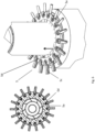
- the nozzle design in the fuel supply line ensures even fuel distribution across the entire circumference of the fuel supply line.
- the nozzle design consists of an annular orifice with holes through which the fuel is fed into the combustion chamber, and injector intake nozzles for intake of exhaust gas from the immediate vicinity, which are built into this annular orifice.
- the injector intake nozzles are positioned along the fuel flow channels.
- the injectors have tubular, elongated intake nozzles on the intake side. The length of the injector intake nozzles is longer on the intake side than the thickness of the primary air supply line, i.e., the injector intake nozzles can intake exhaust gas from the immediate vicinity of the burner directly into the gaseous fuel stream.
- the intake openings of the injector intake nozzles are directed inwards and are in fluid communication with the exhaust gas volume surrounding the secondary air nozzle.
- the design of the exhaust gas intake from the inside or outside depends on the structural conditions of the thermal processing plant to be fired.
- the design with external extraction offers the advantage that the exhaust gas drawn in is cooled in the injector intake pipes by the outflowing primary air.
- the drawn-in and cooled exhaust gas stream is introduced into the fuel stream. This creates a fuel-exhaust gas mixture at the fuel nozzle outlet, which is converted into oxygen in a combustion reaction.
- the exhaust gas component in the fuel stream has a NOx-reducing effect because the peak temperature in the flame remains low, thus producing less thermal NOx.
- the first dead volume serves for thermal insulation and can be filled with a suitable material for thermal insulation between the secondary air and fuel areas.
- the conical taper in the primary air supply line serves to accelerate the primary air flow.
- the adjustable ring orifice and the swirl vanes with adjustable angle of attack serve to uniform distribution of the primary air over the entire circumference of the supply line or to create a vortex structure in the outflowing fluid.
- this arrangement allows the secondary air flow to be fed into the combustion reaction with the fuel at a location offset along the longitudinal axis.
- This arrangement concept enables staged combustion based on air staging.
- a burner can cover a capacity range from 10 kWh to 100,000 kWh, corresponding to an hourly natural gas consumption of 1 m3 to 10,000 m3 .
- the burner can be operated with any gaseous fuel, such as natural gas, methane, ethane, propane, butane, etc., as well as with pulverized solid fuels, such as coal dust, or gasified liquid fuels, such as hydrazine.
- the secondary air supply line can be length-adjustable, with the pipe-in-pipe system for supplying the secondary air extending into the combustion chamber by a length L.
- D the outer diameter of the primary air supply line
- f 0 ⁇ f ⁇ 3.
- approximately one-third of the secondary air supply line can extend into the hot gas side area. This ensures good heat transfer to the secondary air. Preheating the secondary air ensures more stable and complete combustion of the remaining fuel.
- the ratio of (outer diameter of innermost tube of the secondary air supply line) (hereinafter: ADi) : (outer diameter of middle tube of the secondary air supply line) (hereinafter: ADm) : (outer diameter of outermost tube of the secondary air supply line) (hereinafter: ADa) can be approximately 0.7-1.3 : 1.26-2.34 : 1.82-3.38, preferably approximately 1 : 1.8 : 2.6. This represents an excellent geometry that delivers improved combustion results.
- the second dead volume can be approximately 1/5 of the length of the secondary air supply line. This serves to provide thermal insulation between the secondary air area and the fuel supply line.
- the ratio of (inner diameter of the fuel supply line) (hereinafter: IDZ) : (outer diameter of the fuel supply line) (hereinafter: ADZ) can be approximately 0.7-1.3 : 0.98-1.82, preferably approximately 1 : 1.4. This represents an excellent geometry that delivers improved combustion results.
- the ratio of (inner diameter of the primary air supply line) (hereinafter: IDP) : (outer diameter of the primary air supply line) (hereinafter: ADP) can be approximately 0.7-1.3 : 0.91-1.69, preferably approximately 1 : 1.3. This represents an excellent geometry that delivers improved combustion results.
- the first dead volume may have a vacuum or thermal insulation. This ensures that the fuel does not heat up before entering the hot gas side.
- the outermost tube of the secondary air supply line can have overflow channels that open into the first dead volume, and the first dead volume can have partitions that reduce the first dead volume.
- the annular orifice can be adjustable and have passages on the inside. This creates a tertiary air flow that flows into the hot gas side region via an adjustable annular orifice on the inside of the fuel nozzle. This achieves more efficient and stable combustion.
- the radially aligned injector intake nozzle can have at least one guide plate aligned in the same direction as the swirl plate in the primary air supply line. This imparts additional swirl to the primary air. The formation of a vortex flow of the primary air is thereby further supported.
- the outermost pipe of the supply line for secondary air can have a nozzle ring with radially or radially and axially aligned outflow openings at the outlet into the hot gas side region.
- pipe sections can be arranged in the dome-shaped closure of the middle pipe of the secondary air supply line. These pipe sections protrude through the dome-shaped closure at one end and through a dust baffle at the opposite end.
- the backflowing secondary air by means of an injector effect, "carries" exhaust gas from the combustion chamber and mixes it with the secondary air. This gas mixture is combusted with the fuel at the outlet openings of the secondary air supply line.
- the dust baffle creates the back pressure necessary for the injector effect and the associated downstream pressure drop.
- the cross section of the natural gas-carrying annular orifice has an outwardly directed cone, over which the primary air flows.
- This geometry of the annular baffle forces an inward flow of the primary air.
- a cylindrical annular baffle can be placed on the cone to better direct the primary air flow.
- holes can be arranged on the inner side of the annular orifice, which are in fluid communication with the holes in the annular orifice. This allows exhaust gas to be drawn into the fuel stream from the inner side via the injector intake nozzle.
- a supply line for additives can be arranged centrally along the burner axis and protrude through the dome-shaped closure of the middle pipe of the secondary air supply line, which supply line has a nozzle on the hot gas side area.
- the supply line can also be arranged radially around the burner.
- flammable or non-flammable additives such as waste oils and heating oils, fatty solutions of animal or plant origin, organic waste materials and solvents, waste acids and alkalis, wastewater, sulfur-containing liquids, chlorinated and halogenated gases and liquids, can be co-combusted via this additional injection system.
- These substances are fed into the combustion chamber via the additional supply line, which is arranged centrally along the burner axis or radially around the burner.
- the additives are finely atomized and injected into the burner flame via a nozzle. Exhaust gas can also be extracted to the outside through this supply line in countercurrent to the secondary air, thereby preheating the secondary air stream.
- the outlet openings of the pipe sections on the side of the baffles can be narrowed by a longitudinally adjustable cone (valve). This allows the total exhaust gas mass flow in the secondary air flow to be regulated.
- an outer annular gap can be formed by two tubes that surround the burner on the outside, the inner of the two tubes having an opening and the outer of the two tubes having an outlet. Exhaust gas can be drawn out through the outer annular gap in counterflow to the primary air via the outlet located in the outer of the two tubes, thereby preheating the primary air flow.
- the interior of the two tubes creates a closed combustion chamber in which the staged combustion takes place and the hot gases can flow out through the opening located on the interior of the two tubes.
- Another aspect of the invention relates to a method for combustion of fuel in a burner as defined above, wherein secondary air is introduced into the secondary air supply line in a burner as defined above, the secondary air being swirled by the swirl vanes; fuel is introduced into the fuel supply line, the fuel being injected through the holes in the annular orifice at an outward angle of attack into the swirled primary air; primary air is introduced into the primary air supply line, the primary air being swirled by the swirl vanes.
- the proportion of secondary air can be 20-50 vol.% and the proportion of primary air 50-80 vol.% of the total air required for combustion. This distribution ratio results in excellent exhaust gas behavior.
- the total air ratio for the sum of primary and secondary air ⁇ can be about 1.0 to 2.0, preferably about 1.0 to 1.5, in particular about 1.0 to 1.1. This allows a stoichiometric excess of air or oxygen to be used.
- the oxygen concentration in the secondary air and primary air can range from 21 vol.% to 100 vol.%. Accordingly, the nitrogen content decreases with increasing oxygen concentrations. Higher oxygen concentrations allow combustion processes to be conducted much more efficiently, since the combustion temperature and heat transfer based on gas radiation increase significantly with increasing oxygen concentrations in the oxidizer stream. Thus, this burner can achieve increased energy efficiency while simultaneously achieving low NOx emissions.
- the primary air and secondary air can be an air-exhaust gas mixture, an air-oxygen mixture, or an exhaust gas-oxygen mixture.
- the present burner can be used to implement a process for external exhaust gas circulation with oxygen enrichment. A partial exhaust gas flow is diverted from the main flow, enriched with oxygen, and fed to the burner at the primary and secondary air inlets as air replacement. The enthalpy of the recirculated exhaust gas-oxygen mass flow can then be used directly for energy savings. Based on this concept, not only NOx but also CO2 emissions can be drastically reduced.
- the fuel may comprise nitrogen.
- Nitrogen-containing fuels such as hydrazine may be used.
- Hydrocarbons used as fuels may also contain small amounts of nitrogen. With this burner, these nitrogen-laden fuels can be combusted without causing significant NOx emissions.
- the fuel may comprise or be gaseous hydrocarbons, hydrogen, biogases, coal dust-air mixtures, hydrogen sulfides, carbon monoxide gas, carbon monoxide-hydrogen mixtures, coke oven gases, tail gases.
- exhaust gas can be drawn directly into the fuel stream through the injector effect. This results in more efficient NOx reduction.
- the outward-facing injector intake nozzles can be cooled by the outflowing primary air. This minimizes the thermal load on the injector intake nozzles.
- the intake exhaust gas stream can be cooled inside the injector intake nozzles below the condensation temperature (dew point) for the exhaust gas moisture, whereby water in the exhaust stream condenses and the liquid water is introduced into the fuel stream. This also achieves a lower combustion temperature, thereby suppressing thermal NOx formation.
- exhaust gas can be drawn into the secondary air stream, and subsequently an air-exhaust gas mixture is brought to the secondary air nozzle opening for combustion with the injected fuel.
- the introduced exhaust gas reduces the combustion temperature and thus NOx emissions.
- the quantities of the material flows can be automatically controlled for low NOx and CO emissions based on a rigidly functioning programmed logic or a neural network individually trained for the respective process conditions. This makes it easy to comply with legal limits.
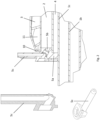
- Fig. 1 shows a cross section of a burner of the invention.
- Fig. 2 shows a cross section of a nozzle construction of the invention.
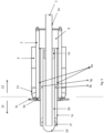
- Fig. 3 shows a burner of the invention with an axial outflow of the secondary air into the hot gas area.
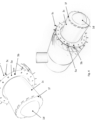
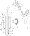
- Fig. 4 shows a three-dimensional view of a burner of the invention.
- Fig. 5 shows an embodiment of the invention with overflow openings and partitions.
- Fig. 6 shows a nozzle construction of an embodiment of the invention.
- Fig. 7 shows another embodiment of the invention with integrated guide vanes on the injector intake nozzles.
- Fig. 8 shows yet another embodiment of the invention with a supply line for additives.
- Fig. 9 shows yet another embodiment of the invention with injector intake pipes for mixing exhaust gas from the combustion chamber into the secondary air flow.
- Fig. 10 shows another embodiment of the invention with an adjustable ring aperture in the primary air supply line.
- Fig. 11 shows a serrated nozzle gap that allows the secondary air to flow out both axially and radially in relation to the longitudinal axis.
- Fig. 12 shows a control concept for regulating the low-NOx burner.
- the secondary air supply line 1a, 1b, 1c is adjustable in length. Approximately 1/3 of the secondary air supply line 1 extends into the hot gas side area 21.
- the ratio of the outer diameter of the innermost pipe 1a of the secondary air supply line : the outer diameter of the middle pipe 1b of the secondary air supply line : the outer diameter of the outermost pipe 1c of the secondary air supply line is approximately 1 : 1.8 : 2.6.
- the second dead volume 9 is approximately 1/5 of the length of the secondary air supply line 1.
- the ratio of the inner diameter of the supply line for fuel 2 : the outer diameter of the supply line for fuel 2 is approximately 1 : 1.4.
- the ratio of the inner diameter of the supply line for primary air 3 : the outer diameter of the supply line for primary air 3 is approximately 1 : 1.3.
- the first dead volume 4 has vacuum or thermal insulation.
- the burner as described in Example 1 is modified as follows: the outermost pipe of the supply line for secondary air 1c has overflow channels 1g, which open into the first dead volume 4, and the first dead volume 4 has partitions 4a, which reduce the first dead volume 4, and the annular orifice 5a is adjustable and has passages 5d on the inside.
- the burner as described in Example 1 or Example 2 has the following modification: the radially aligned injector intake nozzle 5c has at least one guide plate 5e which is aligned in the same way as the swirl plate 11 in the primary air supply line 3.
- the burner as shown in one of the above examples has the following modification: the outermost pipe of the secondary air supply line 1c has a nozzle ring 1h with radially or radially and axially aligned outflow openings at the outlet into the hot gas side region 21.
- the burner as shown in one of the above examples has the following modification: in the dome-shaped closure 1d of the middle pipe of the secondary air supply line 1b, pipe pieces 1i are arranged, which protrude at one end through the dome-shaped closure 1d and at the opposite end through a dust baffle 1j.
- a feed line for additives 2a is arranged centrally along the burner axis and protrudes through the dome-shaped closure of the middle pipe of the feed line for Secondary air 1d, which supply line 2a has a nozzle 2b on the hot gas side area 21.
- secondary air is introduced into the secondary air supply line 1, the secondary air being swirled by the swirl plates 1f; fuel is introduced into the fuel supply line 2, the fuel being injected into the swirled primary air at an outward angle of attack through the holes in the annular orifice 5a; Primary air is introduced into the primary air supply line 3, whereby the primary air is swirled by the swirl plates 11.
- the proportion of secondary air is 40 vol.% and the proportion of primary air is 60 vol.% of the total air required for combustion.
- the total air ratio for the sum of primary and secondary air ⁇ is approximately 1.1.
- the primary air and secondary air is an air-exhaust gas mixture.
- the fuel is natural gas.
- the outwardly directed injector intake nozzles 5c are cooled by the outflowing primary air.
- the quantities of the material flows are controlled based on a rigidly functioning programmed logic for low NOx and CO emissions.
Landscapes
- Engineering & Computer Science (AREA)
- Mechanical Engineering (AREA)
- General Engineering & Computer Science (AREA)
- Chemical & Material Sciences (AREA)
- Combustion & Propulsion (AREA)
Claims (18)
- Brûleur, comprenant une zone côté gaz chaud (21) et une zone extérieure (22), une conduite pour air primaire (3), une conduite pour air secondaire (1), une conduite pour combustible (2), ladite conduite pour air secondaire (1) comprenant trois tuyaux cylindriques disposés de façon concentrique (un tuyau (1a) situé le plus à l'intérieur, un tuyau (1b) central et un tuyau (1c) situé le plus à l'extérieur),ladite conduite pour air secondaire (1) faisant saillie dans ladite zone côté gaz chaud (21) ;ledit tuyau (1a) situé le plus à l'intérieur étant ouvert vers ladite zone extérieure (22) et ouvert vers ledit côté gaz chaud (21) ;ledit tuyau (1b) central étant disposé de façon concentrique autour dudit tuyau (1a) situé le plus à l'intérieur, et présentant une fermeture (1d) en forme de dôme, qui encapsule ledit tuyau (1a) situé le plus à l'intérieur à la manière d'un dôme dudit côté gaz chaud (21), et étant fermé vers ledit côté (22) extérieur ;ledit tuyau (1b) central présentant des canaux de trop-plein (1e), disposés dans ladite zone extérieure (22), présentant des alésages et étant ouverts vers ledit tuyau (1c) situé le plus à l'extérieur ;ledit tuyau (1c) situé le plus à l'extérieur étant fermé vers ladite zone extérieure (22) et ouvert dudit côté (21) gaz chaud et présentant, au niveau de ladite ouverture dudit côté (21) gaz chaud, des aubes de turbulence (1f) ajustables présentant un angle d'attaque compris entre 15 ° et 80 ° ;dans ladite fermeture (1d) en forme de dôme dudit tuyau central de ladite conduite pour air secondaire (1b) étant éventuellement disposés des éléments de tuyau (1i), faisant saillie à travers ladite fermeture (1d) en forme de dôme à l'une des extrémités et faisant saillie à travers une plaque (1j) de restriction à l'extrémité opposée ;ladite conduite pour combustible (2) étant disposée de façon concentrique autour de ladite conduite pour air secondaire (1), qui s'arrête immédiatement après son entrée dans ladite zone côté gaz chaud (21) ;un premier volume mort (4) étant prévu dans l'intérieur dudit brûleur entre ladite conduite pour air secondaire (1) et ladite conduite pour combustible (2) etladite conduite pour combustible (2) présentant, sur ledit côté gaz chaud (21), une construction de buse (5) comprenant le suivant :une plaque annulaire (5a) ayant des orifices (5b) ;des buses (5c) d'injection à aspiration orientées radialement, en communication fluidique avec lesdits orifices (5b) et faisant saillie au-delà du diamètre extérieur de ladite conduite pour air primaire (3) du coté aspiration ;les orifices (5b) dans ladite plaque annulaire (5a) présentant un angle d'attaque de 0 ° à 60 °, de préférence de 10 ° à 45 ° et plus particulièrement de 45 ° ;ladite plaque annulaire (5a) formant un cône tronqué présentant un angle d'attaque de 0 ° à 70 °, de préférence de 20 ° à 45 °, la base du cône étant orientée vers ladite zone extérieure (22) ;un deuxième volume mort (9) étant disposé entre ladite conduite pour air secondaire (1) et ladite conduite pour combustible (2) du côté de ladite zone extérieure (22) ;ladite conduite pour air primaire (3) étant disposée de façon concentrique autour de ladite conduite pour combustible (2), qui s'arrête immédiatement après son entrée dans ladite zone côté gaz chaud (21) et présente le suivant :au niveau de ladite ouverture dudit côté gaz chaud (21), une diminution conique du diamètre, ladite diminution conique formant un cône tronqué présentant un angle de 0 ° à 20 ° ;une plaque annulaire (10) ajustable au niveau de ladite ouverture de ladite diminution conique orientée vers ledit côté gaz chaud (21) ;des aubes de turbulence (11) ajustables par rapport à l'angle d'attaque, disposées selon un angle de 10 ° à 90 °, de préférence de 40 ° à 70 °.
- Brûleur selon la revendication 1, ladite conduite pour air secondaire (1a, 1b, 1c) pouvant être déplacée dans le sens de la longueur, le système tuyau-dans-tuyau pour la conduite d'air secondaire faisant saillie dans la chambre de combustion sur une longueur L, la longueur L satisfaisant la relation L = D * f, D représentant le diamètre extérieur de ladite conduite d'air primaire et f ayant une valeur de 0 ≤ f ≤ 3, ou environ 1/3 de ladite conduite pour air secondaire (1) faisant saillie dans ladite zone (21) côté gaz chaud.
- Brûleur selon l'une des revendications 1 ou 2,le rapport ADi:ADm:ADa étant d'environ 0,7-1,3:1,26-2,34:1,82-3,38, de préférence d'environ 1:1,8:2,6,dans lequel ADi représente le diamètre extérieur dudit tuyau (1a) de ladite conduite pour air secondaire situé le plus à l'intérieur, ADm représente le diamètre extérieur dudit tuyau (1b) central de ladite conduite pour air secondaire et ADa représentant le diamètre extérieur dudit tuyau (1c) de ladite conduite pour air secondaire situé le plus à l'extérieur.
- Brûleur selon l'une quelconque parmi les revendications précédentes,le rapport IDZ:ADZ étant d'environ 0,7-1,3:0,98-1,82, de préférence d'environ 1:1,4,dans lequel IDZ représente le diamètre intérieur de ladite conduite pour combustion (2) et ADZ représente le diamètre extérieur de ladite conduite pour combustion (2).
- Brûleur selon l'une quelconque parmi les revendications précédentes,le rapport IDP:ADP étant d'environ 0,7-1,3:0,91-1,69, de préférence d'environ 1:1,3,dans lequel IDP représente le diamètre intérieur de ladite conduite pour air primaire (3) et ADP représente le diamètre extérieur de ladite conduite pour air primaire (3).
- Brûleur selon l'une quelconque parmi les revendications précédentes,
ledit tuyau (1c) de ladite conduite d'air secondaire situé le plus à l'extérieur présentant des canaux de trop-plein (1g) débouchant dans ledit premier volume mort (4), et ledit premier volume mort (4) présentant des cloisonnements (4a), qui diminuent ledit premier volume mort (4), et ladite plaque annulaire (5a) étant ajustable et présentant des passages (5d) sur sa face interne. - Brûleur selon l'une quelconque parmi les revendications précédentes,
ladite buse (5c) d'injection à aspiration orientée radialement présentant au moins un déflecteur (5e) orienté de la même façon que ladite aube de turbulence (11) dans ladite conduite pour air primaire (3). - Brûleur selon l'une quelconque parmi les revendications précédentes,
ledit tuyau (1c) de ladite conduite d'air secondaire situé le plus à l'extérieur présentant une couronne (1h) de buse ayant des ouvertures d'écoulement orientées radialement ou radialement et axialement au niveau de la sortie dans ladite zone (21) côté gaz chaud. - Brûleur selon l'une quelconque parmi les revendications précédentes,
la section de ladite plaque annulaire (5a), qui conduit du combustible, présentant un cône orienté vers l'extérieur, au-dessus duquel passe l'air primaire. - Brûleur selon l'une quelconque parmi les revendications précédentes,
sur la face intérieure de ladite plaque annulaire (5a) étant disposés des orifices (5f) en communication fluidique avec lesdits orifices (5b) dans ladite plaque annulaire - Brûleur selon l'une quelconque parmi les revendications précédentes,
une conduite pour additifs (2a) étant disposée centralement le long de l'axe dudit brûleur et faisant saillie à travers la fermeture (1d) dudit tuyau central de ladite conduite pour air secondaire en forme de dôme, ladite conduite (2a) présentant une buse (2b) dans ladite zone (21) côté gaz chaud. - Brûleur selon l'une quelconque parmi les revendications précédentes,
les ouvertures d'écoulement desdits éléments de tuyau (1i) pouvant être rétrécies du côté desdites plaques de restriction (1j) par un cône ajustable (vanne) dans le sens de sa longueur. - Brûleur selon l'une quelconque parmi les revendications précédentes,
un interstice annulaire extérieur (1k) étant formé par deux tuyaux (1m, 1n) entourant de l'extérieur ledit brûleur, le plus intérieur desdits deux tuyaux (1m) présentant une ouverture (1o) et le plus extérieur desdits deux tuyaux (1n) présentant une sortie (11). - Procédé pour combustion de combustible, dans lequelde l'air secondaire est introduit dans un brûleur selon l'une quelconque parmi les revendications 1 à 13 dans ladite conduite pour air secondaire (1), l'air secondaire étant mis en rotation par lesdites aubes de turbulence (1f) ;du combustible est introduit dans ladite conduite pour combustible (2), le combustible étant injecté, à travers des orifices dans ladite plaque annulaire (5a), dans l'air primaire mis en rotation, selon un angle d'attaque orienté vers l'extérieur;l'air primaire est introduit dans ladite conduite pour air primaire (3), l'air primaire étant mis en rotation par lesdites aubes de turbulence (11) ;éventuellement le taux d'air secondaire correspondant à 20-50 % en volume et le taux d'air primaire correspondant à 50-80 % en volume par rapport au total d'air nécessaire à la combustion.
- Procédé selon la revendication 14, dans lequella valeur d'air total pour l'ensemble d'air primaire et secondaire λ est d'environ 1,0 à 2,0, de préférence de 1,0 à 1,5 et plus particulièrement d'environ 1,0 à 1,1 ; et/oula concentration d'oxygène dans l'air secondaire et primaire est de 21 % en volume à 100 % en volume ; et/oul'air primaire et secondaire sont un mélange air/gaz d'échappement, un mélange air/oxygène ou un mélange gaz d'échappement/oxygène.
- Procédé selon l'une des revendications 14 ou 15,
le combustible comprenant des composés azotés, des hydrocarbures gazeux, de l'hydrogène, des biogaz, des mélanges poussière de charbon/air, des sulfures d'hydrogène, du gaz de monoxyde de carbone, des mélanges monoxyde de carbone/hydrogène, des gaz de cokerie, des gaz résiduaires ou leur mélanges. - Procédé selon l'une quelconque parmi des revendications 14 à 16,
du gaz d'échappement étant aspiré directement dans le courant de combustible par l'action d'injection. - Procédé selon l'une quelconque parmi des revendications 14 à 17,lesdites buses (5c) d'injection à aspiration étant refroidies par l'air primaire sortant ;le courant de gaz d'échappement aspiré à l'intérieur desdites buses (5c) d'injection à aspiration étant éventuellement refroidi à une température inférieure à la température de condensation (point de condensation) de l'humidité du gaz d'échappement, de l'eau étant condensée dans le courant de gaz d'échappement et l'eau liquide étant introduite dans le courant du combustible.
Applications Claiming Priority (2)
| Application Number | Priority Date | Filing Date | Title |
|---|---|---|---|
| ATA61/2021A AT524888A1 (de) | 2021-03-23 | 2021-03-23 | Ultra-Low-NOx-Brenner |
| PCT/EP2022/057025 WO2022200174A1 (fr) | 2021-03-23 | 2022-03-17 | Brûleur |
Publications (3)
| Publication Number | Publication Date |
|---|---|
| EP4314655A1 EP4314655A1 (fr) | 2024-02-07 |
| EP4314655B1 true EP4314655B1 (fr) | 2025-04-23 |
| EP4314655C0 EP4314655C0 (fr) | 2025-04-23 |
Family
ID=81307457
Family Applications (1)
| Application Number | Title | Priority Date | Filing Date |
|---|---|---|---|
| EP22716206.2A Active EP4314655B1 (fr) | 2021-03-23 | 2022-03-17 | Brûleur |
Country Status (4)
| Country | Link |
|---|---|
| US (1) | US20240175576A1 (fr) |
| EP (1) | EP4314655B1 (fr) |
| AT (1) | AT524888A1 (fr) |
| WO (1) | WO2022200174A1 (fr) |
Families Citing this family (2)
| Publication number | Priority date | Publication date | Assignee | Title |
|---|---|---|---|---|
| CN116576483B (zh) * | 2023-05-16 | 2025-12-02 | 北京航空航天大学 | 一种用于氢燃料亚燃冲压发动机的支板火焰稳定装置 |
| CN120043117B (zh) * | 2025-03-06 | 2025-12-05 | 北京科技大学 | 一种小型低氮燃烧器及燃烧方法 |
Family Cites Families (19)
| Publication number | Priority date | Publication date | Assignee | Title |
|---|---|---|---|---|
| FR1518756A (fr) * | 1967-01-18 | 1968-03-29 | Pillard Chauffage | Brûleur à gaz à flamme rayonnante |
| JPS6086312A (ja) * | 1983-10-19 | 1985-05-15 | Daido Steel Co Ltd | 微粉炭バ−ナ− |
| DE3623103A1 (de) | 1985-07-11 | 1987-03-26 | Vaillant Joh Gmbh & Co | Durchlauf- oder speicherwasserheizer |
| US4659305A (en) * | 1985-12-30 | 1987-04-21 | Aqua-Chem, Inc. | Flue gas recirculation system for fire tube boilers and burner therefor |
| AT391195B (de) | 1987-09-21 | 1990-08-27 | Vaillant Gmbh | Verfahren zur verbrennung fluessiger oder gasfoermiger brennstoffe und vorrichtung zur durchfuehrung des verfahrens |
| DE4133176A1 (de) | 1991-10-07 | 1993-04-08 | Wulff Maschf Appbau Gmbh | Brenner fuer fluessige und/oder gasfoermige brennstoffe |
| DE4435640C2 (de) * | 1994-10-06 | 2001-01-04 | Steinmueller Gmbh L & C | Brenner zur Verbrennung von staubförmigem Brennstoff |
| US5709541A (en) * | 1995-06-26 | 1998-01-20 | Selas Corporation Of America | Method and apparatus for reducing NOx emissions in a gas burner |
| US5807094A (en) * | 1997-08-08 | 1998-09-15 | Mcdermott Technology, Inc. | Air premixed natural gas burner |
| US6652268B1 (en) * | 2003-01-31 | 2003-11-25 | Astec, Inc. | Burner assembly |
| DE102004010063A1 (de) * | 2004-03-02 | 2005-09-22 | Khd Humboldt Wedag Ag | Drehofenbrenner |
| DE102004059888A1 (de) | 2004-12-10 | 2006-06-22 | Dr. Wiedmann Kg | Brenner |
| DE102006060867B4 (de) * | 2006-12-22 | 2020-07-02 | Khd Humboldt Wedag Gmbh | Drehofenbrenner |
| JP5707897B2 (ja) | 2010-11-25 | 2015-04-30 | 株式会社Ihi | 微粉燃料焚きボイラ装置 |
| EP2498002B1 (fr) | 2011-03-08 | 2016-05-11 | Elster GmbH | Brûleur industriel à haute efficacité |
| US8920159B2 (en) * | 2011-11-23 | 2014-12-30 | Honeywell International Inc. | Burner with oxygen and fuel mixing apparatus |
| US20130255551A1 (en) * | 2012-03-27 | 2013-10-03 | American Air Liquide, Inc. | Biomass Combustion |
| US20140182491A1 (en) * | 2012-12-31 | 2014-07-03 | Air Liquide, Societe Anonyme pour Etude et Exploitation des Procedes Gorges Claude | Biomass combustion |
| EP3217094B2 (fr) * | 2016-03-11 | 2023-06-28 | Air Products And Chemicals, Inc. | Brûleur et procédé de combustion |
-
2021
- 2021-03-23 AT ATA61/2021A patent/AT524888A1/de unknown
-
2022
- 2022-03-17 EP EP22716206.2A patent/EP4314655B1/fr active Active
- 2022-03-17 US US18/283,500 patent/US20240175576A1/en active Pending
- 2022-03-17 WO PCT/EP2022/057025 patent/WO2022200174A1/fr not_active Ceased
Also Published As
| Publication number | Publication date |
|---|---|
| AT524888A1 (de) | 2022-10-15 |
| US20240175576A1 (en) | 2024-05-30 |
| EP4314655C0 (fr) | 2025-04-23 |
| WO2022200174A1 (fr) | 2022-09-29 |
| EP4314655A1 (fr) | 2024-02-07 |
Similar Documents
| Publication | Publication Date | Title |
|---|---|---|
| DE2461078C2 (de) | Verfahren zur Verringerung des Gehalts an Stickstoffoxiden, Kohlenmonoxid und Kohlenstoff in einem Abgas, sowie Feuerungsanlage zur Durchführung des Verfahrens | |
| DE2415036C2 (de) | Brennkammer für Gasturbinentriebwerke mit Regenerativ-Wärmetauschern | |
| DE69828916T2 (de) | Emissionsarmes Verbrennungssystem für Gasturbinentriebwerke | |
| DE69303617T2 (de) | BRENNER ZUR NOx-ARMEN VERBRENNUNG MIT GESTUFTER LUFTZUFUHR UND ABGASRÜCKFÜHRUNG | |
| DE102011008009B4 (de) | Verfahren zum Betreiben einer Gasturbine und Gasturbine | |
| DE2940431A1 (de) | Brennkammer mit abgestufter brennstoffeinspritzung und verfahren zum betreiben einer hochtemperaturbrennkammer | |
| EP0463218A1 (fr) | Procédé et dispositif de combustion du combustible dans une chambre de combustion | |
| CH680014A5 (fr) | ||
| DE2841637A1 (de) | Brenneranlage zum verbrennen gasfoermiger oder fluessiger brennstoffe | |
| DE3041177A1 (de) | Brenner | |
| DE112011103722T5 (de) | Brennkammer für Gasturbine für niederkalorischen Teibstoff | |
| EP4314655B1 (fr) | Brûleur | |
| DE10055613A1 (de) | Verfahren zur Zufuhr von Brennstoff und/oder thermischer Energie in einen Gasstrom | |
| WO2017140631A1 (fr) | Unité brûleur et dispositif de mise en température d'objets | |
| EP0040690B1 (fr) | Dispositif pour la combustion de matières oxydables dans les gaz d'échappement | |
| EP0602396B1 (fr) | Méthode de exploitation d'un générateur de chaleur | |
| EP0484777B1 (fr) | Procédé pour la stabilisation d'un processus de combustion | |
| EP1754937B1 (fr) | Tête de brûleur et procédé pour brûler du combustible | |
| DE4422535A1 (de) | Verfahren zum Betrieb einer Feuerungsanlage | |
| DE3043286A1 (de) | Verbrennungseinrichtung zur verbrennung von stoerstoffen in abgasen | |
| DE19542644B4 (de) | Vormischverbrennung | |
| EP2453174B1 (fr) | Dispositif de brûleur a tube rayonnant avec récupération interne et externe | |
| DE4436728A1 (de) | Verfahren und Vorrichtung für eine schadstoffarme gestufte Verbrennung | |
| EP0543155B1 (fr) | Procédé pour une combustion peu polluante dans une chaudère de centrale électrique | |
| DE4417539A1 (de) | Verfahren zur luftgeblasenen Vergasung von kohlenstoffhaltigen Brennstoffen |
Legal Events
| Date | Code | Title | Description |
|---|---|---|---|
| STAA | Information on the status of an ep patent application or granted ep patent |
Free format text: STATUS: UNKNOWN |
|
| STAA | Information on the status of an ep patent application or granted ep patent |
Free format text: STATUS: THE INTERNATIONAL PUBLICATION HAS BEEN MADE |
|
| PUAI | Public reference made under article 153(3) epc to a published international application that has entered the european phase |
Free format text: ORIGINAL CODE: 0009012 |
|
| STAA | Information on the status of an ep patent application or granted ep patent |
Free format text: STATUS: REQUEST FOR EXAMINATION WAS MADE |
|
| 17P | Request for examination filed |
Effective date: 20231023 |
|
| AK | Designated contracting states |
Kind code of ref document: A1 Designated state(s): AL AT BE BG CH CY CZ DE DK EE ES FI FR GB GR HR HU IE IS IT LI LT LU LV MC MK MT NL NO PL PT RO RS SE SI SK SM TR |
|
| DAV | Request for validation of the european patent (deleted) | ||
| DAX | Request for extension of the european patent (deleted) | ||
| GRAP | Despatch of communication of intention to grant a patent |
Free format text: ORIGINAL CODE: EPIDOSNIGR1 |
|
| STAA | Information on the status of an ep patent application or granted ep patent |
Free format text: STATUS: GRANT OF PATENT IS INTENDED |
|
| INTG | Intention to grant announced |
Effective date: 20241119 |
|
| GRAS | Grant fee paid |
Free format text: ORIGINAL CODE: EPIDOSNIGR3 |
|
| GRAA | (expected) grant |
Free format text: ORIGINAL CODE: 0009210 |
|
| STAA | Information on the status of an ep patent application or granted ep patent |
Free format text: STATUS: THE PATENT HAS BEEN GRANTED |
|
| AK | Designated contracting states |
Kind code of ref document: B1 Designated state(s): AL AT BE BG CH CY CZ DE DK EE ES FI FR GB GR HR HU IE IS IT LI LT LU LV MC MK MT NL NO PL PT RO RS SE SI SK SM TR |
|
| REG | Reference to a national code |
Ref country code: GB Ref legal event code: FG4D Free format text: NOT ENGLISH |
|
| REG | Reference to a national code |
Ref country code: CH Ref legal event code: EP |
|
| REG | Reference to a national code |
Ref country code: DE Ref legal event code: R096 Ref document number: 502022003676 Country of ref document: DE |
|
| REG | Reference to a national code |
Ref country code: IE Ref legal event code: FG4D Free format text: LANGUAGE OF EP DOCUMENT: GERMAN |
|
| U01 | Request for unitary effect filed |
Effective date: 20250515 |
|
| U07 | Unitary effect registered |
Designated state(s): AT BE BG DE DK EE FI FR IT LT LU LV MT NL PT RO SE SI Effective date: 20250521 |
|
| PG25 | Lapsed in a contracting state [announced via postgrant information from national office to epo] |
Ref country code: ES Free format text: LAPSE BECAUSE OF FAILURE TO SUBMIT A TRANSLATION OF THE DESCRIPTION OR TO PAY THE FEE WITHIN THE PRESCRIBED TIME-LIMIT Effective date: 20250423 |
|
| PG25 | Lapsed in a contracting state [announced via postgrant information from national office to epo] |
Ref country code: NO Free format text: LAPSE BECAUSE OF FAILURE TO SUBMIT A TRANSLATION OF THE DESCRIPTION OR TO PAY THE FEE WITHIN THE PRESCRIBED TIME-LIMIT Effective date: 20250723 Ref country code: GR Free format text: LAPSE BECAUSE OF FAILURE TO SUBMIT A TRANSLATION OF THE DESCRIPTION OR TO PAY THE FEE WITHIN THE PRESCRIBED TIME-LIMIT Effective date: 20250724 |
|
| PG25 | Lapsed in a contracting state [announced via postgrant information from national office to epo] |
Ref country code: PL Free format text: LAPSE BECAUSE OF FAILURE TO SUBMIT A TRANSLATION OF THE DESCRIPTION OR TO PAY THE FEE WITHIN THE PRESCRIBED TIME-LIMIT Effective date: 20250423 |
|
| PG25 | Lapsed in a contracting state [announced via postgrant information from national office to epo] |
Ref country code: HR Free format text: LAPSE BECAUSE OF FAILURE TO SUBMIT A TRANSLATION OF THE DESCRIPTION OR TO PAY THE FEE WITHIN THE PRESCRIBED TIME-LIMIT Effective date: 20250423 |
|
| PG25 | Lapsed in a contracting state [announced via postgrant information from national office to epo] |
Ref country code: RS Free format text: LAPSE BECAUSE OF FAILURE TO SUBMIT A TRANSLATION OF THE DESCRIPTION OR TO PAY THE FEE WITHIN THE PRESCRIBED TIME-LIMIT Effective date: 20250723 |
|
| PG25 | Lapsed in a contracting state [announced via postgrant information from national office to epo] |
Ref country code: IS Free format text: LAPSE BECAUSE OF FAILURE TO SUBMIT A TRANSLATION OF THE DESCRIPTION OR TO PAY THE FEE WITHIN THE PRESCRIBED TIME-LIMIT Effective date: 20250823 |
|
| PG25 | Lapsed in a contracting state [announced via postgrant information from national office to epo] |
Ref country code: SM Free format text: LAPSE BECAUSE OF FAILURE TO SUBMIT A TRANSLATION OF THE DESCRIPTION OR TO PAY THE FEE WITHIN THE PRESCRIBED TIME-LIMIT Effective date: 20250423 |
|
| PG25 | Lapsed in a contracting state [announced via postgrant information from national office to epo] |
Ref country code: CZ Free format text: LAPSE BECAUSE OF FAILURE TO SUBMIT A TRANSLATION OF THE DESCRIPTION OR TO PAY THE FEE WITHIN THE PRESCRIBED TIME-LIMIT Effective date: 20250423 |
|
| PG25 | Lapsed in a contracting state [announced via postgrant information from national office to epo] |
Ref country code: SK Free format text: LAPSE BECAUSE OF FAILURE TO SUBMIT A TRANSLATION OF THE DESCRIPTION OR TO PAY THE FEE WITHIN THE PRESCRIBED TIME-LIMIT Effective date: 20250423 |
|
| PLBE | No opposition filed within time limit |
Free format text: ORIGINAL CODE: 0009261 |
|
| STAA | Information on the status of an ep patent application or granted ep patent |
Free format text: STATUS: NO OPPOSITION FILED WITHIN TIME LIMIT |
|
| REG | Reference to a national code |
Ref country code: CH Ref legal event code: L10 Free format text: ST27 STATUS EVENT CODE: U-0-0-L10-L00 (AS PROVIDED BY THE NATIONAL OFFICE) Effective date: 20260304 |
|
| 26N | No opposition filed |
Effective date: 20260126 |