EP4316271A2 - Procédé de fabrication de tabac reconstitué - Google Patents
Procédé de fabrication de tabac reconstitué Download PDFInfo
- Publication number
- EP4316271A2 EP4316271A2 EP23209014.2A EP23209014A EP4316271A2 EP 4316271 A2 EP4316271 A2 EP 4316271A2 EP 23209014 A EP23209014 A EP 23209014A EP 4316271 A2 EP4316271 A2 EP 4316271A2
- Authority
- EP
- European Patent Office
- Prior art keywords
- strip
- subjected
- mixture
- tobacco
- lamination
- Prior art date
- Legal status (The legal status is an assumption and is not a legal conclusion. Google has not performed a legal analysis and makes no representation as to the accuracy of the status listed.)
- Pending
Links
Images



Classifications
-
- A—HUMAN NECESSITIES
- A24—TOBACCO; CIGARS; CIGARETTES; SIMULATED SMOKING DEVICES; SMOKERS' REQUISITES
- A24B—MANUFACTURE OR PREPARATION OF TOBACCO FOR SMOKING OR CHEWING; TOBACCO; SNUFF
- A24B3/00—Preparing tobacco in the factory
- A24B3/14—Forming reconstituted tobacco products, e.g. wrapper materials, sheets, imitation leaves, rods, cakes; Forms of such products
-
- A—HUMAN NECESSITIES
- A24—TOBACCO; CIGARS; CIGARETTES; SIMULATED SMOKING DEVICES; SMOKERS' REQUISITES
- A24B—MANUFACTURE OR PREPARATION OF TOBACCO FOR SMOKING OR CHEWING; TOBACCO; SNUFF
- A24B15/00—Chemical features or treatment of tobacco; Tobacco substitutes, e.g. in liquid form
- A24B15/10—Chemical features of tobacco products or tobacco substitutes
- A24B15/12—Chemical features of tobacco products or tobacco substitutes of reconstituted tobacco
- A24B15/14—Chemical features of tobacco products or tobacco substitutes of reconstituted tobacco made of tobacco and a binding agent not derived from tobacco
-
- A—HUMAN NECESSITIES
- A24—TOBACCO; CIGARS; CIGARETTES; SIMULATED SMOKING DEVICES; SMOKERS' REQUISITES
- A24B—MANUFACTURE OR PREPARATION OF TOBACCO FOR SMOKING OR CHEWING; TOBACCO; SNUFF
- A24B3/00—Preparing tobacco in the factory
- A24B3/04—Humidifying or drying tobacco bunches or cut tobacco
-
- A—HUMAN NECESSITIES
- A24—TOBACCO; CIGARS; CIGARETTES; SIMULATED SMOKING DEVICES; SMOKERS' REQUISITES
- A24B—MANUFACTURE OR PREPARATION OF TOBACCO FOR SMOKING OR CHEWING; TOBACCO; SNUFF
- A24B3/00—Preparing tobacco in the factory
- A24B3/08—Blending tobacco
-
- A—HUMAN NECESSITIES
- A24—TOBACCO; CIGARS; CIGARETTES; SIMULATED SMOKING DEVICES; SMOKERS' REQUISITES
- A24B—MANUFACTURE OR PREPARATION OF TOBACCO FOR SMOKING OR CHEWING; TOBACCO; SNUFF
- A24B3/00—Preparing tobacco in the factory
- A24B3/10—Roasting or cooling tobacco
-
- A—HUMAN NECESSITIES
- A24—TOBACCO; CIGARS; CIGARETTES; SIMULATED SMOKING DEVICES; SMOKERS' REQUISITES
- A24B—MANUFACTURE OR PREPARATION OF TOBACCO FOR SMOKING OR CHEWING; TOBACCO; SNUFF
- A24B3/00—Preparing tobacco in the factory
- A24B3/12—Steaming, curing, or flavouring tobacco
-
- A—HUMAN NECESSITIES
- A24—TOBACCO; CIGARS; CIGARETTES; SIMULATED SMOKING DEVICES; SMOKERS' REQUISITES
- A24B—MANUFACTURE OR PREPARATION OF TOBACCO FOR SMOKING OR CHEWING; TOBACCO; SNUFF
- A24B5/00—Stripping tobacco; Treatment of stems or ribs
- A24B5/10—Stripping tobacco; Treatment of stems or ribs by crushing the leaves with subsequent separating
-
- A—HUMAN NECESSITIES
- A24—TOBACCO; CIGARS; CIGARETTES; SIMULATED SMOKING DEVICES; SMOKERS' REQUISITES
- A24B—MANUFACTURE OR PREPARATION OF TOBACCO FOR SMOKING OR CHEWING; TOBACCO; SNUFF
- A24B7/00—Cutting tobacco
-
- A—HUMAN NECESSITIES
- A24—TOBACCO; CIGARS; CIGARETTES; SIMULATED SMOKING DEVICES; SMOKERS' REQUISITES
- A24B—MANUFACTURE OR PREPARATION OF TOBACCO FOR SMOKING OR CHEWING; TOBACCO; SNUFF
- A24B9/00—Control of the moisture content of tobacco products, e.g. cigars, cigarettes, pipe tobacco
Definitions
- the present invention relates to a method for producing reconstituted tobacco, both of the conventional type and of the non-conventional type, the latter also referred to as H N B (Heat Not Burn).
- the reconstituted tobacco is obtained by using tobacco by-products and processing waste (ribs, small pieces of leaves, dust, etc.) which, properly shredded until they are practically reduced to powder and mixed with water, glycerine binders and other liquid additives, allow to obtain an extremely fluid mixture (slurry) having a liquid content of about 70% by weight, which is then poured into a veil on a steel belt and with this transferred into a drying oven.
- slurry extremely fluid mixture
- the evaporation of the liquid fraction of the mixture takes place, so that the solid residue forms a sort of continuous tobacco strip having approximately the same width as the steel belt.
- the strip of dried mixture is separated from the steel belt and is cut into pieces of various sizes depending on the request.
- the reconstituted tobacco is distinguished as conventional or unconventional.
- WO 2016/050469 , WO 2016/050470 , WO 2016/050471 , WO 2016/050472 describe known techniques of production of reconstituted tobacco, which require plants of considerable size and involve high energy consumption to bring the mixture, which when it is produced is rather fluid, to the consistency of a tobacco sheet. It is sufficient to point out that a drying oven can reach 100 m in length.
- the object of the invention is to eliminate these drawbacks and to produce reconstituted tobacco of both conventional and unconventional types, with implants of much smaller dimensions.
- Another object of the invention is to produce reconstituted tobacco with limited energy consumption.
- Another object of the invention is to produce reconstituted tobacco using equipment partly already available on the market, even if never used in this specific technical field.
- Another object of the invention is to produce reconstituted tobacco which is alternative to traditional methods.
- Another object of the invention is to produce reconstituted tobacco with characteristics suitable for satisfying different market demands.
- Another object of the invention is to produce reconstituted tobacco operating at low temperature and thus preserving all the aromas of tobacco.
- the method according to the invention for producing reconstituted tobacco is characterized in that it comprises the carrying out, in sequence, of the following steps:
- a plant for producing reconstituted tobacco which can be used to carry out the method according to the invention, comprises several sections arranged in series and aimed at operating on the input raw materials until they are transformed into a continuous strip of reconstituted tobacco to be sent for subsequent packaging operations of the cigarettes.
- the plant for the production of reconstituted tobacco comprises:
- the plant 1 also comprises a mixture forming unit 92 for forming a plurality of portions 97 of said mixture; suitably, therefore, the first lamination unit 100 is configured to obtain, from the portions 97 of said mixture, a continuous strip having a thickness of about 1-20 mm, preferably of about 1-10 mm.
- the plant comprises:
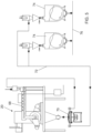
- the section for preparing and pre-treating the starting solid products is different depending on whether the implant is intended to produce reconstituted conventional tobacco ( fig. 2 ) or non- conventional type ( fig. 3 ).
- it may be provided also a section of preparation and pre-treatment of the tobacco ribs ( fig. 4 ), to be used for the production of reconstituted tobacco both conventional type that unconventional type.
- the preparation and pre-treatment section in the case in which the preparation and pre-treatment section is intended to supply a plant for the production of reconstituted tobacco of the conventional type ( fig. 2 ), it includes a tilter 2 of cartons containing tobacco products, to overturn their contents on a feeder 4 of a vibrating conveyor 6, which separates any heavy bodies from the product to be treated.
- the heavy bodies are collected in a suitable container 8, while the product to be treated is transferred, through a pneumatic conveyor line 10, to a cyclone 12, a conveyor belt 14, provided with metal detector 16 for the removal of any metal bodies, and a pneumatic conveying line or 18, to a mill 20, advantageously of the cryogenic type.
- the preparation and pre-treatment section is provided for the preparation of reconstituted tobacco of an unconventional type ( fig. 3 ), it comprises a feeding station with a counter 22 for unloading the bales of tobacco leaves from cartons of approximately 200 kg, which typically contain them, and the transfer of these to a grinder 24.
- the output of this grinder 24 is connected, through a pneumatic conveying line 26, to a cyclone 28, in which the transport air is separated from the solid product, which is transferred to a vibrating sieve 30 for the separation of the fine parts from the remaining parts of the product.
- the output of the fine parts is directly connected with the cryogenic mill 20, while the output of the remaining parts of the product feeds a conventional twine remove machine 32, which provides for eliminating any twine previously not removed from the bales of tobacco leaves.
- the exit of the twine remove machine 32 feeds a separation chamber 34 for the separation of any heavy foreign bodies from the ground tobacco leaves, which through a pneumatic conveyor line 36, a cyclone 38, a strip conveyor 40, provided with metal detectors 42 for removing any metal bodies, and a pneumatic conveyor line 44, are transferred to the cryogenic mill 20.
- the preparation and pre - treatment section is provided for the preparation of the tobacco ribs to be used for the production of reconstituted tobacco of both the conventional and the non-conventional type ( Fig. 4 ), it comprises a tipper 46 for cartons containing the ribs of tobacco, feeder 48 for the ribs to a vibrating conveyor 50, for the separation from these of any heavy bodies, and a pneumatic transport line 52 for their movement to a hammer mill 54, where they are comminuted.
- the hammer mill 54 has its output connected, via a pneumatic conveyor line 56 provided with cyclone filters 58, to one or more storage silos 60.
- the output of the of the storage silo or silos 60 is in turn connected, by means of a screw conveyor 62, to a metering device 64, which provides for dosing the shredded ribs before sending them to the mill 20, preferably cryogenic, through a pneumatic line of transport 66.
- the plant also includes the mill 20 ( Fig. 5 ), which carries out the grinding of various products received to bring them to an average particle size of about 20 - 220 ⁇ m, preferably about 80-180 ⁇ m.
- the mill 20 Fig. 5
- Various types of mills can be used, although it is more advantageous to use a cryogenic rungs mill, which allows the product to be kept at low process temperatures and therefore to retain tobacco aromas.
- the pinned-disk mill is in itself conventional and includes a closed structure with inside a fixed and a rotating disc or two counter-rotating discs, provided with rungs facing and partially interpenetrating each other. Being an apparatus in itself traditional, it has been globally indicated with 20 in fig. 5 but is not shown in its internal construction characteristics or in its operating modes.
- the rungs mill 20 is predisposed to make a cryogenic grinding, namely a grinding in the presence of liquid nitrogen.
- a cryogenic pin mill is somewhat more advantageous than a traditional mill, essentially due to the different ways in which the products to be ground are treated. In fact, grinding at room temperature can lead to obtaining products of poor quality, while grinding in the presence of liquid nitrogen preserves the physical properties and the chemical and organoleptic characteristics of the products.
- the amount of liquid nitrogen used in cryogenic grinding processes is a fundamental part to consider when the pros and cons of the process are studied and may vary depending on the materials processed.
- the liquid nitrogen at a temperature of -175°C is injected onto the product inside the chamber of a screw conveyor 68 which feeds the mill 20 and its residence time in contact with nitrogen is about 2 to 5 sec., which is also the transit time of the product inside the cochlea that feeds the pin mill.
- the temperature of the product coming out of the mill 20 is advantageously less than 10°C, in a way that the nitrogen vapours, which are released almost instantaneously upon contact with the tobacco to be cooled, travel upstream all of mill feed system, performing the desired pre-cooling effect.
- thermocouples that make the cryogenically grinding process fully automatic.
- cryogenic grinding the positive factors of cryogenic grinding are:
- the output of the rungs cryogenic mill 20 is connected to a fluidized sieve bed 70, which has the function of separating the ground product, which exits from the mill itself and typically has an average particle size of about 20 - 220 ⁇ m, preferably about 80-180 ⁇ m, from particles of larger sizes, inevitably present.
- the sieve with a fluidized bed therefore has the function of sorting the product and put back into the cycle in the mill 20 the one with fractions greater than 120 ⁇ m, after having them separated from those comprised between 20 ⁇ m and 120 ⁇ m, that through a line of pneumatic conveying 72 are sent to one or more mixing and storage silos 74.
- the output of the of mixing and storage silos 74 feeds, via a pneumatic transport line 76, and a cyclone filter 78, which has the function of breaking down the dusty air and more specifically to separate the dust, which then is recovered and fed back into the cycle, from the air, which can then be ejected.
- the output of the cyclone filter 78 feeds, through a continuous dosing system, preferably with a screw, the kneader 80, which can be of various types, for example of a horizontal type with overturning or a vertical spiral type.
- the kneading machine 80 is fed with a quantity of minced tobacco, water, at least one binding agent and at least one material to form an aerosol and is configured to obtain a mixture with a liquid content of about 30-50%, preferably by about 35-40%.
- the values of liquid or humidity are intended to be determined according to the measurement system on a wet basis.
- the humidity values are defined as the percentage of water contained in the total mass of the corresponding product and, in other words, it is the percentage ratio between the quantity of water and the total mass of the mixture.
- these values are obtained using the traditional methods provided in the literature for measuring the quantity of water in a product, such as those presented in " Tobacco Moisture, Water and Oven Volatiles - A status report of common moisture methods used within the tobacco industry" By Nils Rose ET AL. in “Analytical and bioanalytical chemistry” (1 July 2014, pages 1-16 ).
- to kneader 80 is headed at least a duct or water inlet, of a material for the formation of aerosols (e.g. glycerine) and at least one binding agent (binder).
- a material for the formation of aerosols e.g. glycerine
- binding agent e.g. glycerine
- one or more inlet ducts can be provided for other additives required by the particular recipe to be prepared.
- the system includes one or more tanks 82 for the storage of material for the formation of aerosols and one or more pre-mixers 84, in which can be entered said material for the formation of aerosols and, preferably, a plurality of additives dosed in the right proportions to form the liquid to be introduced into the mixer 80.
- preferred materials for the formation of the aerosol include polyhydric alcohols (e.g. Glycerol, propylene glycol, triethylene glycol and tetraethylene glycol), aliphatic esters of mono-, di- or poly-carboxylic acids (e.g.
- glycerine, propylene glycol, triethylene glycol and tetraethylene glycol can be mixed together to form an aerosol forming material.
- the aerosol forming material can also be supplied as a portion of the binding agent (e.g., when the binding agent is alginate propylene glycol).
- suitable combinations of materials for the formation of the aerosol can also be provided.
- said at least one agent and a binder comprises at least one of hydroxypropyl cellulose, hydroxypropyl methylcellulose, hydroxyethyl cellulose, microcrystalline cellulose, methylcellulose, carboxymethylcellulose (CMC), corn starch, potato starch, guar gum, carob seed flour, pectins and alginates (for example ammonium alginate and sodium alginate).
- CMC carboxymethylcellulose
- pectins and alginates for example ammonium alginate and sodium alginate.
- the output of the pre-mixer the 84 is connected with the input of a hydrator 86, having other inputs connected with a line 88 of water and with a supply line 90 to supply compressed air.
- the output of the mixer 80 feeds to the forming units 92 the mixture to obtain a plurality of portions 97, preferably conformed to breads/loaves and separated from each other.
- the forming unit 92 includes a pair of forming rollers 96, presenting grooves preferably parallel to the axis of cylinders and configured to pick up the incoming mixture and to output the portions 97.
- the forming unit 92 is also configured to perform a roughing mixture and for this purpose, preferably, comprises a hopper 94 provided with a break lumps in its interior and of said pair of forming rollers 96 on the bottom.
- the first lamination unit 100 comprises a lobed feeder 102.
- a further metal detector 104 along the transfer path from the forming unit 92 to the lobed feeder 102 may be provided a further metal detector 104, whose function is to remove any metal parts, that may still be present in the mixture and may damage the subsequent processing units. These metal parts are conveyed along a distinctive path to the inlet of the lobed feeder 102 and are collected within a suitable container 106.
- the lobed feeder 102 comprises a series of feeding lobed rollers, between which are conveyed the portions 97 (which come from the forming rollers 96 of the forming unit 92) so as to push them between a displaced couple of rolling cylinders 108, which are configured so as to form a continuous strip having a thickness of about 1-20 mm, preferably of about 1-10 mm.
- the rolling line 116 may be provided directly downstream of the lobed feeder 102.
- the rolling line receives the continuous strip input, having thickness of about 1-20 mm, preferably of about 1-10 mm, which exits from the first lamination unit 100 provided in the lobed feeder 102.
- a stratification unit 110 downstream of the first lamination unit 100 and upstream of the rolling line 116, a stratification unit 110 can be provided downstream of the first lamination unit 100 and upstream of the rolling line 116.
- said stratification unit 110 consists of an upstream conveyor belt 112, which has the function of depositing on a lower downstream conveyor belt 114, preferably belonging to the rolling line 116, the product strip arranging it so that it is stratified on said downstream conveyor belt 114, for example folding it several times on itself.
- the upstream conveyor belt 112 is raised above the downstream conveyor belt 114 and is provided with a continuous advancement movement with respect to its supporting structure, and at the same time with a reciprocating motion with its supporting structure, parallel to the its longitudinal axis.
- the stratification unit 110 feeds the lower successive rolling line 116 and depending on the type of plant the upstream conveyor belt 112 stratification unit 110 may be arranged parallel or perpendicular to the rolling line 116.
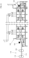
- the upstream conveyor belt 112 is disposed parallel to the downstream conveyor belt 114 provided it the rolling line 116 ( fig. 1 ), while if the downstream conveyor belt 114 of the rolling line 116 are wider than the product that exits the stratification unit 110, it is preferable that the upstream conveyor belt 112 is arranged orthogonally to the downstream conveyor belt 114 provided of the rolling line 116 ( fig. 8 ), so that with its movements can distribute the product strip on the whole useful width of the rolling line 116.
- the reciprocating movement of the structure supporting the upstream conveyor belt 112 stratification unit 110 causes a stratification of the strip of product, which exits from the first lamination unit 100 on the underlying first downstream conveyor belt 114 of the rolling line 116 and the formation of a stratified strip of width substantially equal to the useful width of the rolling line itself.
- the rolling line 116 is formed by several lamination stations, each comprising a pair of cylinders 118, which delimit between them an increasingly narrow passage to gradually reduce the strip thickness of the product being processed.
- the rolling line 116 is configured to progressively bring the endless strip to a thickness of 90-280 ⁇ m, preferably about 140-200 ⁇ m.
- a downstream conveyor belt 114 having a length of preferably about 1.5-2 m, which has the function to rest the product before it is subjected to the next step of lamination.
- the rolling line 116 is then completed with one or more calibration stations, each formed by a pair of calibrating cylinders 120.
- the laminating cylinders 118 and possibly also the calibrating cylinders 120 can be heated, so as to be able to start the drying step already during the rolling.
- the dryer 122 can be divided into two units 124, 126, placed in series with respect to each other. More particularly, the upstream unit 124 is provided to perform the first drying step and it presents in its interior a carrier made steel sheet or of a mesh conveyor belt for the transport of the product that comes out of the rolling line 16; the downstream unit 126 is provided to perform the second drying step and the subsequent cooling step and is provided inside with a mesh conveyor belt.
- the dryer 122 is advantageously provided at the entrance and exit of sensors 128, preferably with infrared rays, which control the product along its entire length.
- the containers of tobacco scraps are placed on the tipper 2, which reverses the products on the feeder 4, which transfers them to the vibrating conveyor 6.
- the separation of heavy bodies from the tobacco by-products the former are collected in the container 8 while the latter are transferred by an air flux along the pneumatic conveying line 10 up to the cyclone 12, which separates the air from solid products and let these fall on the conveyor 14, for their transfer, through the pneumatic line 18, to the cryogenic mill 20.
- the cartons containing the tobacco leaves are placed in the unpacking bench 22, where the individual bales of tobacco leaves are removed from the cartons and sent to the grinder 24, which reduces the leaves themselves to a substantially uniform size of between 5 and 10 mm.
- the thus comminuted product is then transferred along the pneumatic conveying line 26 to the cyclone 28, which separates it from the air and makes it fall on the vibrating sieve 30.
- cryogenic mill 20 can also be transferred, if the recipe requires it, the shredded tobacco ribs, which can be used for the production of reconstituted tobacco of both conventional and non-conventional type.
- the containers with the ribs are placed on the tilter 46, which feeds the ribs themselves to the vibrating conveyor 50 for the removal of any heavy bodies.
- the ribs are then transferred through the pneumatic line 52 to the hammer mill 54, which shreds them to reduce them to a size between 5 and 8 mm.
- the shredded ribs, separated in the cyclones 58 by the conveying air, are transferred to the storage silos 60, from which the different types of ribs, coming from different qualities of tobacco, can be withdrawn and transferred through the screw conveyor 62 to the doser of the ribs 64, which doses them according to the particular recipe to be prepared.
- the ribs, shredded and dosed in the correct quantities, are transferred via the pneumatic line transport 66 to the cryogenic mill 20.
- a ground product with an average particle size of approximately 20 - 220 ⁇ m, preferably about 80-180 ⁇ m.
- the ground product which comes out of the sieve with a fluid bed fed by the cryogenic mill 20, has an average particle size of about 20 - 220 ⁇ m, preferably about 80-180 ⁇ m.
- the product thus ground is sent to the mixing and storage silos 60, from which the products can then be taken according to requirements and transferred to the kneading machine 80.
- the mixer 80 in addition to the ground tobacco (and preferably the solid products from blending silos and storage 60), also water, at least one binding agent and at least one material to form an aerosol are introduced. Preferably, compressed air and other additives are also added.
- the whole is then mixed together to form a mixture having a percentage of liquids (humidity) of about 30-50%, preferably of about 35-40%, by weight on a wet basis, i.e. a rather dense consistency.
- the mixture thus obtained is transferred to the forming unit 92, from which a plurality of portions 97 emerge, preferably shaped like loaves.
- the portions 97 of mixture, which emerge from the forming unit 92 are transferred at the first lamination unit 100 which is configured to output a continuous ribbon thickness of about 1-20 mm, preferably about 1-10 mm.
- This continuous strip which comes from the first lamination unit 100, is directly transferred to the rolling line 116 or - by means of the stratification unit 110 - is folded onto itself so as to be deposited in stratified form on the input strip 114 of the rolling line 116.
- the stratification is obtained by dropping the continuous strip on the conveyor belt 112, which is made to advance with respect to its support structure, which moves of reciprocating motion, so as to have more than one layer of the product strip on said downstream conveyor belt 114.
- the product strip can be arranged on several layers parallel to the longitudinal direction of the rolling line 116 or orthogonally to it.
- the strip of product undergoes a reduction in thickness, up to reach, in correspondence with the displaced output calibrating cylinders 120, the desired thickness, which has a value substantially constant of about 90-280 ⁇ m, preferably of about 140-200 ⁇ m.
- the strip has a liquid content lower to 20% or even 15%, in case the displaced cylinders 118 are heated and the water is removed already during the rolling process.
- the product strip coming out of the rolling line 116 is then subjected to drying in the dryer 122, where its liquid content is brought to about 8-15%.
- the dryer 122 is in air recirculation, which compared to the driers traditionally used in production systems of reconstituted tobacco is more advantageous in terms of complexity both in terms of encumbrance and in terms of energy consumption. This is because the traditional systems treat a product (mixture) very fluid and little stable, unlike the treated product from the plant according to the invention, which is much denser and much more stable.
- the plant can advantageously use an air recirculating dryer 122 with a net conveyor or a combined system of steel belt conveyors for the first drying step and mesh strip conveyors for the second drying step and the cooling step.
- reduced size about 45 m compared to more than 100 m of a traditional drier
- lower energy consumption given the lower amount of water to be removed (using approximately 1000 kg/hour of steam/hour compared to over 5000 kg/hour of steam from a traditional dryer).
- the product is ready to be wound in a reel or to be shredded into strands of the prescribed size, to be used for the packaging of cigarettes.
- the plant in case the plant is provided for the production of reconstituted tobacco of the unconventional type, in addition to using the different preparation and treatment section already described, it uses, as an alternative to the forming unit 92 or in addition and upstream of this, a refiner to cylinder refiner 130 which has the task of bringing the solid components of the mixture to a particle size of not more than 20 ⁇ m.
- the refiner ( fig. 6 ) comprises within a closed container a plurality of cylinders 132 arranged in sequence in narrow closeness between them, so as to delimit the corresponding milling gaps.
- the lower cylinder 132 is mounted with the axis outside the plane containing the axis of all the other cylinders 132 and functions as a feeder of the mixture which is taken from the bottom of the container and made re rise upwards so as to pass between the lower cylinder and the one immediately above and then to follow among all the others.
- the various pairs of cylinders 132 between which the mixture passes rotate at different speeds, in the sense that the upper cylinder rotates at a speed greater than the lower cylinder, with which it cooperates, in order to subject the mixture to a stretch during the passing between the cylinders 132 of each pair and thereby reducing the particle size of the mixture itself.
- One of the fundamental parameters for the success of the refining process is precisely the different speeds of the different cylinders 132, from which depends the passage of the entire mass of the mixture which has passed through the milling gap.
- the pressure between the cylinders is hydraulically controlled.
- All cylinders 132 are cooled with cold water that circulates inside each cylinder and thereby counteracts the heat which is developed from mixing due to friction due to both the movement of the cylinders itself and the rubbing with the product. In this way the temperature of the product is reduced to 25°C.
- the action of friction which is exerted on the mixture by the cylinders 132 of the former, develops a considerable binding action of the cellulose fibres contained in tobacco and in particular in its ribs, and this generates the double advantage of developing the aromatic components of the product and eliminating the need to introduce other fiber into the mixture to obtain the required bonding effect.
- the operation of the plant in this different embodiment requires that the shredded leaves and chopped ribs coming from the preparation and pre-treatment stations are fed to a rungs cryogenic mill 20 in an amount proportionally metered according to the recipe to obtain, and from this are brought to a particle size of about 20 - 220 ⁇ m, preferably about 80-180 ⁇ m.
- the product is then transferred in the manner already described in the mixer 80, in which a product mixture is formed as described above.
- the mixture thus obtained is then fed to the cylinder refiner 130, which has the task of bringing the solid components of the mixture to a particle size not exceeding 20 ⁇ m.
- the action of friction exerted on the mixture by the cylinders 132 of the cylinder refiner 130 develops a considerable binding action of the cellulose fibers contained in the tobacco and in particular in its ribs, and this causes the dual advantage of developing, on one hand, the aromatic components of the product and, on the other hand, eliminating the need to introduce other fibers into the mixture to obtain the required bonding effect.
- Fig. 1 schematically indicates the position of the cylinder refiner 130 between the kneading machine 80 and the forming unit 92, but the invention also provides that the cylinder refiner 130 can be an alternative to the forming unit 92, and in this case the mixture which exits from the cylinder refiner 130 is transferred directly to the first lamination unit 100, for the continuation of the processing cycle according to the methods already described.
Landscapes
- Chemical & Material Sciences (AREA)
- Chemical Kinetics & Catalysis (AREA)
- General Chemical & Material Sciences (AREA)
- Manufacture Of Tobacco Products (AREA)
- Manufacturing Of Cigar And Cigarette Tobacco (AREA)
Applications Claiming Priority (3)
| Application Number | Priority Date | Filing Date | Title |
|---|---|---|---|
| IT201800008652 | 2018-09-17 | ||
| EP19783692.7A EP3852554B1 (fr) | 2018-09-17 | 2019-09-12 | Procédé et appareil pour la production de tabac reconstitué |
| PCT/IB2019/057713 WO2020058814A1 (fr) | 2018-09-17 | 2019-09-12 | Production et usine pour la production de tabac reconstitué |
Related Parent Applications (2)
| Application Number | Title | Priority Date | Filing Date |
|---|---|---|---|
| EP19783692.7A Division EP3852554B1 (fr) | 2018-09-17 | 2019-09-12 | Procédé et appareil pour la production de tabac reconstitué |
| EP19783692.7A Division-Into EP3852554B1 (fr) | 2018-09-17 | 2019-09-12 | Procédé et appareil pour la production de tabac reconstitué |
Publications (2)
| Publication Number | Publication Date |
|---|---|
| EP4316271A2 true EP4316271A2 (fr) | 2024-02-07 |
| EP4316271A3 EP4316271A3 (fr) | 2024-03-27 |
Family
ID=64744796
Family Applications (2)
| Application Number | Title | Priority Date | Filing Date |
|---|---|---|---|
| EP23209014.2A Pending EP4316271A3 (fr) | 2018-09-17 | 2019-09-12 | Procédé de fabrication de tabac reconstitué |
| EP19783692.7A Active EP3852554B1 (fr) | 2018-09-17 | 2019-09-12 | Procédé et appareil pour la production de tabac reconstitué |
Family Applications After (1)
| Application Number | Title | Priority Date | Filing Date |
|---|---|---|---|
| EP19783692.7A Active EP3852554B1 (fr) | 2018-09-17 | 2019-09-12 | Procédé et appareil pour la production de tabac reconstitué |
Country Status (10)
| Country | Link |
|---|---|
| US (1) | US20220030927A1 (fr) |
| EP (2) | EP4316271A3 (fr) |
| JP (1) | JP7512259B2 (fr) |
| KR (1) | KR102907842B1 (fr) |
| CN (1) | CN112888322B (fr) |
| HR (1) | HRP20241111T1 (fr) |
| HU (1) | HUE067968T2 (fr) |
| LT (1) | LT3852554T (fr) |
| PL (1) | PL3852554T3 (fr) |
| WO (1) | WO2020058814A1 (fr) |
Families Citing this family (30)
| Publication number | Priority date | Publication date | Assignee | Title |
|---|---|---|---|---|
| HUE067968T2 (hu) | 2018-09-17 | 2024-12-28 | Comas Costruzioni Macch Speciali S P A | Eljárás és üzem helyreállított dohány elõállítására |
| PL3897225T3 (pl) * | 2018-12-18 | 2023-03-20 | Philip Morris Products S.A. | Sposób i urządzenie do wytwarzania arkusza materiału zawierającego alkaloidy |
| EP4090177B1 (fr) * | 2020-01-16 | 2026-04-08 | Körber Technologies S.p.A. | Procédé de fabrication de substances végétales et / ou alcaloïdes reconstituées et installation de mise en oeuvre dudit procédé |
| IT202000005503A1 (it) * | 2020-03-13 | 2021-09-13 | Comas Costruzioni Macch Speciali S P A | Metodo ed impianto di produzione di tabacco ricostituito. |
| CN113693260B (zh) * | 2020-05-20 | 2023-02-21 | 秦皇岛烟草机械有限责任公司 | 一种形成均质化烟草薄片的方法 |
| WO2021233372A1 (fr) * | 2020-05-20 | 2021-11-25 | 秦皇岛烟草机械有限责任公司 | Système de production de feuilles de tabac homogénéisées et procédé de production |
| CN113772387A (zh) * | 2020-05-20 | 2021-12-10 | 秦皇岛烟草机械有限责任公司 | 一种均质化烟草薄片生产系统 |
| JPWO2022230885A1 (fr) | 2021-04-26 | 2022-11-03 | ||
| CN117597034A (zh) | 2021-04-27 | 2024-02-23 | 日本烟草产业株式会社 | 非燃烧加热型香味抽吸器用烟草片、非燃烧加热型香味抽吸器、以及非燃烧加热型香味抽吸系统 |
| EP4331387A4 (fr) | 2021-04-27 | 2025-04-30 | Japan Tobacco Inc. | Feuille de tabac pour inhalateur d'arôme de type à chauffage sans combustion, inhalateur d'arôme de type à chauffage sans combustion, et système d'inhalation d'arôme de type à chauffage sans combustion |
| WO2023033054A1 (fr) | 2021-09-01 | 2023-03-09 | 日本たばこ産業株式会社 | Feuille de tabac pour inhalateur d'arôme de type chauffage sans combustion, inhalateur d'arôme de type chauffage sans combustion, et système d'inhalation d'arôme de type chauffage sans combustion |
| JP2024540833A (ja) | 2021-10-21 | 2024-11-06 | ジェイティー インターナショナル エスエイ | エアロゾル生成デバイスで使用するためのタバコ基材、消耗物品、並びに関連する製造方法及び最適化方法 |
| CN113876019B (zh) * | 2021-10-26 | 2023-01-31 | 湖北中烟工业有限责任公司 | 一种以烟草边角料为原料制备加热不燃烧卷烟薄片的方法 |
| KR20240153318A (ko) | 2022-02-21 | 2024-10-22 | 제이티 인터내셔널 소시에떼 아노님 | 에어로졸 생성 물품 |
| IT202200003467A1 (it) * | 2022-02-24 | 2023-08-24 | Comas Costruzioni Macch Speciali S P A | Metodo ed impianto per la produzione di un nastro di materiale ricostituito |
| IT202200003446A1 (it) | 2022-02-24 | 2023-08-24 | Comas Costruzioni Macch Speciali S P A | Metodo ed unita' per la raffinazione di uno strato di materiale ricostituito |
| IT202200014227A1 (it) * | 2022-07-06 | 2024-01-06 | Comas Costruzioni Macch Speciali S P A | Metodo per la produzione di uno strato in materiale ricostituito di origine vegetale |
| IT202200021042A1 (it) | 2022-10-12 | 2024-04-12 | Comas Costruzioni Macch Speciali S P A | Metodo ed impianto per la produzione di un nastro di materiale ricostituito |
| KR20250094660A (ko) | 2022-10-24 | 2025-06-25 | 제이티 인터내셔널 소시에떼 아노님 | 에어로졸 생성 장치용 평면형 소모품, 및 연관된 에어로졸 생성 조립체 및 제조 방법 |
| CN116076770B (zh) * | 2023-02-15 | 2026-03-13 | 江苏中烟工业有限责任公司 | 提升辊压法薄片均质化的方法 |
| CN115969077B (zh) * | 2023-02-15 | 2025-11-28 | 江苏中烟工业有限责任公司 | 提升辊压法薄片均质化的系统 |
| JP2026506817A (ja) | 2023-03-10 | 2026-02-26 | ジェイティー インターナショナル エスエイ | 複数の平板状エアロゾル発生基材の製造方法及び関連するたばこ物品 |
| EP4681556A1 (fr) | 2023-03-13 | 2026-01-21 | Japan Tobacco Inc. | Feuille de tabac pour inhalateur d'arôme de type à chauffage sans combustion, inhalateur d'arôme de type à chauffage sans combustion et système d'inhalation d'arôme de type à chauffage sans combustion |
| IT202300006300A1 (it) | 2023-03-31 | 2024-10-01 | Comas Costruzioni Macch Speciali S P A | Metodo ed impianto per la produzione di un nastro a base di cellulosa. |
| CN121001585A (zh) | 2023-04-07 | 2025-11-21 | 菲利普莫里斯生产公司 | 用于生产用于气溶胶生成制品的气溶胶生成基质片材的方法 |
| GB202306392D0 (en) * | 2023-04-28 | 2023-06-14 | Nicoventures Trading Ltd | Aerosol generating material |
| CN121487647A (zh) | 2023-07-17 | 2026-02-06 | 菲利普莫里斯生产公司 | 用于生产用于气溶胶生成制品的气溶胶生成基质片材的设备及方法 |
| WO2025061381A1 (fr) | 2023-09-22 | 2025-03-27 | Philip Morris Products S.A. | Appareil et procédé de production d'une feuille coulée pour un article à fumer |
| WO2025190930A1 (fr) | 2024-03-12 | 2025-09-18 | Jt International Sa | Procédé de production d'un substrat pour un article de génération d'aérosol et substrat associé |
| WO2026012644A1 (fr) | 2024-07-12 | 2026-01-15 | Philip Morris Products S.A. | Appareil et procédé de production d'une feuille de substrat de génération d'aérosol pour articles de génération d'aérosol |
Citations (7)
| Publication number | Priority date | Publication date | Assignee | Title |
|---|---|---|---|---|
| WO2016050470A1 (fr) | 2014-09-30 | 2016-04-07 | Philip Morris Products S.A. | Procédé pour la production de matière à base de tabac homogénéisée |
| WO2016050469A1 (fr) | 2014-09-30 | 2016-04-07 | Philip Morris Products S.A. | Procédé pour la production d'un produit à base de tabac homogénéisé |
| WO2016050472A1 (fr) | 2014-09-30 | 2016-04-07 | Philip Morris Products S.A. | Procédé de production d'un matériau de tabac homogénéisé, et matériau de tabac homogénéisé |
| WO2016050471A1 (fr) | 2014-09-30 | 2016-04-07 | Philip Morris Products S.A. | Substance de tabac homogénéisée et procédé de production de substance de tabac homogénéisée |
| EP3075266A1 (fr) | 2015-04-02 | 2016-10-05 | PT. Gudang Garam Tbk. | Procédé de production d'un article générant un aérosol contenant un matériau à base de tabac reconstitué, article générant un aérosol contenant un matériau à base de tabac reconstitué et utilisation d'un article générant un aérosol contenant un matériau à base de tabac reconstitué |
| WO2019157576A1 (fr) | 2018-02-16 | 2019-08-22 | Ioto International Indústria E Comércio De Produtos Aromáticos Ltda | Procédé et système pour la production de films végétaux reconstitués |
| EP3852554A1 (fr) | 2018-09-17 | 2021-07-28 | COMAS - COSTRUZIONI MACCHINE SPECIALI - S.p.A. | Production et usine pour la production de tabac reconstitué |
Family Cites Families (39)
| Publication number | Priority date | Publication date | Assignee | Title |
|---|---|---|---|---|
| US2708175A (en) | 1954-05-28 | 1955-05-10 | Max M Samfield | Composition of matter consisting chiefly of fragmented tobacco and galactomannan plant gum |
| US2845933A (en) | 1954-05-28 | 1958-08-05 | Liggett & Myers Tobacco Co | Process of converting fragmented tobacco into coherent sheets |
| US2769734A (en) | 1955-07-14 | 1956-11-06 | Int Cigar Mach Co | Tobacco sheet material and method of forming |
| US3009835A (en) | 1960-04-06 | 1961-11-21 | Liggett & Myers Tobacco Co | Novel reconstituted tobacco compositions |
| DE1215567B (de) | 1963-12-06 | 1966-04-28 | Heinr Borgwaldt Fa | Verfahren zur Herstellung von folien- oder blattartigen Gebilden (Flakes) aus zerkleinertem Tabak, Tabakmischungen oder anderen Pflanzenteilen |
| DE1532042B2 (de) | 1966-01-20 | 1977-04-14 | Borgwaldt geb. Murken, Ilse; Grunwald, Georg, Dr.; Otto, Hans-Dietrich, Dr.; 2000 Hamburg | Vorrichtung zur herstellung von folien- oder blattartigen tabakgebilden |
| SE343749B (fr) * | 1969-12-15 | 1972-03-20 | Arenco Ab | |
| US3897791A (en) * | 1971-08-12 | 1975-08-05 | Asahi Chemical Ind | Substitute smoking material employing degraded cellulose |
| BE788844A (fr) * | 1971-09-23 | 1973-01-02 | Imp Tobacco Group Ltd | Renforcement de la nicotine des produits a fumer |
| GB1459218A (en) * | 1973-04-13 | 1976-12-22 | Imp Group Ltd | Method and apparatus for making a web of reconstituted tobacco |
| DE2421652C3 (de) * | 1974-05-04 | 1984-01-19 | Eduard Gerlach GmbH Chemische Fabrik, 4990 Lübbecke | Verfahren zur Herstellung von Tabakfolien und Anlage zur Durchführung des Verfahrens |
| GB1531463A (en) * | 1975-07-08 | 1978-11-08 | Molins Ltd | Manufacture of smokers' articles |
| LU74233A1 (fr) * | 1976-01-23 | 1977-07-27 | ||
| US4270552A (en) * | 1977-10-04 | 1981-06-02 | Brown & Williamson Tobacco Corporation | Process and apparatus for producing paper reconstituted tobacco |
| US4325391A (en) * | 1979-01-05 | 1982-04-20 | Amf Incorporated | Instantaneous slurry preparation on a continuous basis |
| US4446678A (en) * | 1980-09-24 | 1984-05-08 | Smith Teddy V | Material processing machinery |
| JPS6039423B2 (ja) * | 1982-11-13 | 1985-09-05 | 増幸産業株式会社 | 低温摩砕装置 |
| GB8910279D0 (en) * | 1989-05-04 | 1989-06-21 | Gbe International Plc | Improvements in or relating to apparatus for treating tobacco |
| US5247947A (en) * | 1990-02-27 | 1993-09-28 | R. J. Reynolds Tobacco Company | Cigarette |
| US5584306A (en) | 1994-11-09 | 1996-12-17 | Beauman; Emory | Reconstituted tobacco material and method of its production |
| CN1041490C (zh) * | 1994-11-24 | 1999-01-06 | 中国科学院安徽光学精密机械研究所 | 一种高效自动化辊压法烟草薄片生产设备 |
| ATE228781T1 (de) * | 1996-02-02 | 2002-12-15 | British American Tobacco Co | Verfahren und einrichtung zur kurzzeitigen trocknung von tabak |
| CN1290453C (zh) * | 2003-05-21 | 2006-12-20 | 南昌卷烟厂 | 烟草皱纹薄片的制造方法 |
| DE102004008642A1 (de) * | 2004-02-19 | 2005-09-08 | Hauni Primary Gmbh | Verfahren und Vorrichtung zum Entfernen von Fremdstoffen aus zu verarbeitendem Tabak |
| GB2414393B (en) * | 2004-05-24 | 2008-06-11 | Natraceutical Sa | Process for producing cocoa polyphenol concentrate |
| CN1903043A (zh) * | 2005-07-27 | 2007-01-31 | 北京腾威机械有限公司 | 一种面片压延方法、面片压延机组及其面片和面食品 |
| US7861728B2 (en) | 2006-02-10 | 2011-01-04 | R.J. Reynolds Tobacco Company | Smokeless tobacco composition having an outer and inner pouch |
| US7608164B2 (en) * | 2007-02-27 | 2009-10-27 | Georgia-Pacific Consumer Products Lp | Fabric-crepe process with prolonged production cycle and improved drying |
| WO2012131918A1 (fr) * | 2011-03-29 | 2012-10-04 | 日本たばこ産業株式会社 | Procédé de fabrication de côtes broyées, appareil pour fabriquer des côtes broyées et côtes broyées |
| US20130340773A1 (en) * | 2012-06-22 | 2013-12-26 | R.J. Reynolds Tobacco Company | Composite tobacco-containing materials |
| WO2014020699A1 (fr) * | 2012-07-31 | 2014-02-06 | 日本たばこ産業株式会社 | Dispositif de mesure de poids de tabac en feuille, procédé de mesure de celui-ci, système de fabrication de tabac en feuille et procédé de fabrication de celui-ci |
| CN117502539A (zh) | 2013-08-02 | 2024-02-06 | 施韦特-莫迪国际公司 | 包含经重构植物材料的可食用产品 |
| KR101679531B1 (ko) * | 2014-05-14 | 2016-11-24 | 필립모리스 프로덕츠 에스.에이. | 담배 시트들을 결합하기 위한 장치 및 방법 |
| CN105286076B (zh) * | 2014-07-07 | 2019-11-15 | Comas-建设专用机股份公司 | 用于处理烟草肋的方法 |
| WO2016067226A1 (fr) * | 2014-10-29 | 2016-05-06 | Recon Inc. | Tabac reconstitué par nano-stratification |
| WO2016073211A1 (fr) * | 2014-11-04 | 2016-05-12 | Alliance Machine Systems International, Llc | Système d'élimination de rebuts |
| JP7022059B2 (ja) | 2015-11-27 | 2022-02-17 | フィリップ・モーリス・プロダクツ・ソシエテ・アノニム | 均質化したたばこ材料の生産ライン、および均質化したたばこ材料のインライン生産のための方法 |
| CN106235376A (zh) * | 2016-09-30 | 2016-12-21 | 湖北中烟工业有限责任公司 | 一种适用于加热非燃烧型卷烟的再造烟叶 |
| KR102638408B1 (ko) * | 2017-05-24 | 2024-02-21 | 필립모리스 프로덕츠 에스.에이. | 염기성 ph 조절제를 포함하는 균질화된 식물 재료 |
-
2019
- 2019-09-12 HU HUE19783692A patent/HUE067968T2/hu unknown
- 2019-09-12 KR KR1020217011312A patent/KR102907842B1/ko active Active
- 2019-09-12 US US17/276,125 patent/US20220030927A1/en active Pending
- 2019-09-12 EP EP23209014.2A patent/EP4316271A3/fr active Pending
- 2019-09-12 HR HRP20241111TT patent/HRP20241111T1/hr unknown
- 2019-09-12 EP EP19783692.7A patent/EP3852554B1/fr active Active
- 2019-09-12 WO PCT/IB2019/057713 patent/WO2020058814A1/fr not_active Ceased
- 2019-09-12 LT LTEPPCT/IB2019/057713T patent/LT3852554T/lt unknown
- 2019-09-12 PL PL19783692.7T patent/PL3852554T3/pl unknown
- 2019-09-12 JP JP2021513991A patent/JP7512259B2/ja active Active
- 2019-09-12 CN CN201980069126.5A patent/CN112888322B/zh active Active
Patent Citations (8)
| Publication number | Priority date | Publication date | Assignee | Title |
|---|---|---|---|---|
| WO2016050470A1 (fr) | 2014-09-30 | 2016-04-07 | Philip Morris Products S.A. | Procédé pour la production de matière à base de tabac homogénéisée |
| WO2016050469A1 (fr) | 2014-09-30 | 2016-04-07 | Philip Morris Products S.A. | Procédé pour la production d'un produit à base de tabac homogénéisé |
| WO2016050472A1 (fr) | 2014-09-30 | 2016-04-07 | Philip Morris Products S.A. | Procédé de production d'un matériau de tabac homogénéisé, et matériau de tabac homogénéisé |
| WO2016050471A1 (fr) | 2014-09-30 | 2016-04-07 | Philip Morris Products S.A. | Substance de tabac homogénéisée et procédé de production de substance de tabac homogénéisée |
| EP3075266A1 (fr) | 2015-04-02 | 2016-10-05 | PT. Gudang Garam Tbk. | Procédé de production d'un article générant un aérosol contenant un matériau à base de tabac reconstitué, article générant un aérosol contenant un matériau à base de tabac reconstitué et utilisation d'un article générant un aérosol contenant un matériau à base de tabac reconstitué |
| WO2019157576A1 (fr) | 2018-02-16 | 2019-08-22 | Ioto International Indústria E Comércio De Produtos Aromáticos Ltda | Procédé et système pour la production de films végétaux reconstitués |
| US20210244069A1 (en) | 2018-02-16 | 2021-08-12 | Ioto International Indústria E Comércio De Produtos Aromáticos Ltd | Method and System For Producing of Reconstituted Vegetable Films |
| EP3852554A1 (fr) | 2018-09-17 | 2021-07-28 | COMAS - COSTRUZIONI MACCHINE SPECIALI - S.p.A. | Production et usine pour la production de tabac reconstitué |
Non-Patent Citations (1)
| Title |
|---|
| NILS ROSE ET AL., ANALYTICAL AND BIOANALYTICAL CHEMISTRY, 1 July 2014 (2014-07-01), pages 1 - 16 |
Also Published As
| Publication number | Publication date |
|---|---|
| BR112021004940A2 (pt) | 2021-06-01 |
| HUE067968T2 (hu) | 2024-12-28 |
| JP2022500043A (ja) | 2022-01-04 |
| EP4316271A3 (fr) | 2024-03-27 |
| JP7512259B2 (ja) | 2024-07-08 |
| CN112888322A (zh) | 2021-06-01 |
| LT3852554T (lt) | 2024-09-25 |
| WO2020058814A1 (fr) | 2020-03-26 |
| KR102907842B1 (ko) | 2026-01-05 |
| EP3852554B1 (fr) | 2024-06-12 |
| CN112888322B (zh) | 2023-03-28 |
| PL3852554T3 (pl) | 2024-11-25 |
| US20220030927A1 (en) | 2022-02-03 |
| HRP20241111T1 (hr) | 2024-11-08 |
| EP3852554A1 (fr) | 2021-07-28 |
| KR20210075095A (ko) | 2021-06-22 |
Similar Documents
| Publication | Publication Date | Title |
|---|---|---|
| EP3852554B1 (fr) | Procédé et appareil pour la production de tabac reconstitué | |
| EP4117459B1 (fr) | Procédé et installation de production de tabac reconstitué | |
| EP4120851B1 (fr) | Procédé de production de feuilles homogènes de fibres végétales sans nicotine | |
| CZ452190A3 (cs) | Způsob zpracování tabákových listů | |
| CN114901085A (zh) | 用于生产再造植物物质和/或再造生物碱物质的方法和实施该方法的设备 | |
| RS59242B1 (sr) | Postupak za obradu trave ili sena | |
| WO1994010864A1 (fr) | Cigarette et procede de preparation | |
| RU73590U1 (ru) | Линия по переработке продуктов пчеловодства (варианты) | |
| DE10214644A1 (de) | Instantierte modifizierte Mehle | |
| KR100792011B1 (ko) | 고춧가루 제조 시스템 | |
| HK40086608A (en) | Method and plant for producing reconstituted tobacco | |
| HK40086608B (en) | Method and plant for producing reconstituted tobacco | |
| HK40086607A (en) | Method of producing homogeneous sheets of nicotine-free vegetable fibers | |
| HK40086607B (en) | Method of producing homogeneous sheets of nicotine-free vegetable fibers | |
| BR112021004940B1 (pt) | Método e planta para a produção de tabaco reconstituído | |
| CN105710953A (zh) | 农作物秸秆原料加工方法 | |
| RU19251U1 (ru) | Комплекс по переработке водорослей | |
| CN116491679B (zh) | 再造烟叶薄片制造方法和装置 | |
| WO2024079646A1 (fr) | Procédé et installation de production d'une bande de matériau reconstitué | |
| DE29817434U1 (de) | Anlage zur Aufbereitung von Altbackwaren |
Legal Events
| Date | Code | Title | Description |
|---|---|---|---|
| PUAI | Public reference made under article 153(3) epc to a published international application that has entered the european phase |
Free format text: ORIGINAL CODE: 0009012 |
|
| STAA | Information on the status of an ep patent application or granted ep patent |
Free format text: STATUS: THE APPLICATION HAS BEEN PUBLISHED |
|
| AC | Divisional application: reference to earlier application |
Ref document number: 3852554 Country of ref document: EP Kind code of ref document: P |
|
| AK | Designated contracting states |
Kind code of ref document: A2 Designated state(s): AL AT BE BG CH CY CZ DE DK EE ES FI FR GB GR HR HU IE IS IT LI LT LU LV MC MK MT NL NO PL PT RO RS SE SI SK SM TR |
|
| PUAL | Search report despatched |
Free format text: ORIGINAL CODE: 0009013 |
|
| AK | Designated contracting states |
Kind code of ref document: A3 Designated state(s): AL AT BE BG CH CY CZ DE DK EE ES FI FR GB GR HR HU IE IS IT LI LT LU LV MC MK MT NL NO PL PT RO RS SE SI SK SM TR |
|
| RIC1 | Information provided on ipc code assigned before grant |
Ipc: A24B 3/14 20060101AFI20240220BHEP |
|
| STAA | Information on the status of an ep patent application or granted ep patent |
Free format text: STATUS: REQUEST FOR EXAMINATION WAS MADE |
|
| 17P | Request for examination filed |
Effective date: 20240924 |
|
| RBV | Designated contracting states (corrected) |
Designated state(s): AL AT BE BG CH CY CZ DE DK EE ES FI FR GB GR HR HU IE IS IT LI LT LU LV MC MK MT NL NO PL PT RO RS SE SI SK SM TR |
|
| TPAC | Observations filed by third parties |
Free format text: ORIGINAL CODE: EPIDOSNTIPA |
|
| STAA | Information on the status of an ep patent application or granted ep patent |
Free format text: STATUS: EXAMINATION IS IN PROGRESS |
|
| 17Q | First examination report despatched |
Effective date: 20260219 |