EP4317704A1 - Fluidkreislauf - Google Patents
Fluidkreislauf Download PDFInfo
- Publication number
- EP4317704A1 EP4317704A1 EP22780186.7A EP22780186A EP4317704A1 EP 4317704 A1 EP4317704 A1 EP 4317704A1 EP 22780186 A EP22780186 A EP 22780186A EP 4317704 A1 EP4317704 A1 EP 4317704A1
- Authority
- EP
- European Patent Office
- Prior art keywords
- pressure
- accumulator
- oil passage
- throttle valve
- pressure detector
- Prior art date
- Legal status (The legal status is an assumption and is not a legal conclusion. Google has not performed a legal analysis and makes no representation as to the accuracy of the status listed.)
- Pending
Links
Images




Classifications
-
- F—MECHANICAL ENGINEERING; LIGHTING; HEATING; WEAPONS; BLASTING
- F15—FLUID-PRESSURE ACTUATORS; HYDRAULICS OR PNEUMATICS IN GENERAL
- F15B—SYSTEMS ACTING BY MEANS OF FLUIDS IN GENERAL; FLUID-PRESSURE ACTUATORS, e.g. SERVOMOTORS; DETAILS OF FLUID-PRESSURE SYSTEMS, NOT OTHERWISE PROVIDED FOR
- F15B1/00—Installations or systems with accumulators; Supply reservoir or sump assemblies
- F15B1/02—Installations or systems with accumulators
- F15B1/024—Installations or systems with accumulators used as a supplementary power source, e.g. to store energy in idle periods to balance pump load
-
- F—MECHANICAL ENGINEERING; LIGHTING; HEATING; WEAPONS; BLASTING
- F15—FLUID-PRESSURE ACTUATORS; HYDRAULICS OR PNEUMATICS IN GENERAL
- F15B—SYSTEMS ACTING BY MEANS OF FLUIDS IN GENERAL; FLUID-PRESSURE ACTUATORS, e.g. SERVOMOTORS; DETAILS OF FLUID-PRESSURE SYSTEMS, NOT OTHERWISE PROVIDED FOR
- F15B2201/00—Accumulators
- F15B2201/50—Monitoring, detection and testing means for accumulators
- F15B2201/51—Pressure detection
-
- F—MECHANICAL ENGINEERING; LIGHTING; HEATING; WEAPONS; BLASTING
- F15—FLUID-PRESSURE ACTUATORS; HYDRAULICS OR PNEUMATICS IN GENERAL
- F15B—SYSTEMS ACTING BY MEANS OF FLUIDS IN GENERAL; FLUID-PRESSURE ACTUATORS, e.g. SERVOMOTORS; DETAILS OF FLUID-PRESSURE SYSTEMS, NOT OTHERWISE PROVIDED FOR
- F15B2211/00—Circuits for servomotor systems
- F15B2211/20—Fluid pressure source, e.g. accumulator or variable axial piston pump
- F15B2211/205—Systems with pumps
- F15B2211/2053—Type of pump
- F15B2211/20546—Type of pump variable capacity
-
- F—MECHANICAL ENGINEERING; LIGHTING; HEATING; WEAPONS; BLASTING
- F15—FLUID-PRESSURE ACTUATORS; HYDRAULICS OR PNEUMATICS IN GENERAL
- F15B—SYSTEMS ACTING BY MEANS OF FLUIDS IN GENERAL; FLUID-PRESSURE ACTUATORS, e.g. SERVOMOTORS; DETAILS OF FLUID-PRESSURE SYSTEMS, NOT OTHERWISE PROVIDED FOR
- F15B2211/00—Circuits for servomotor systems
- F15B2211/20—Fluid pressure source, e.g. accumulator or variable axial piston pump
- F15B2211/21—Systems with pressure sources other than pumps, e.g. with a pyrotechnical charge
- F15B2211/212—Systems with pressure sources other than pumps, e.g. with a pyrotechnical charge the pressure sources being accumulators
-
- F—MECHANICAL ENGINEERING; LIGHTING; HEATING; WEAPONS; BLASTING
- F15—FLUID-PRESSURE ACTUATORS; HYDRAULICS OR PNEUMATICS IN GENERAL
- F15B—SYSTEMS ACTING BY MEANS OF FLUIDS IN GENERAL; FLUID-PRESSURE ACTUATORS, e.g. SERVOMOTORS; DETAILS OF FLUID-PRESSURE SYSTEMS, NOT OTHERWISE PROVIDED FOR
- F15B2211/00—Circuits for servomotor systems
- F15B2211/30—Directional control
- F15B2211/305—Directional control characterised by the type of valves
- F15B2211/30505—Non-return valves, i.e. check valves
-
- F—MECHANICAL ENGINEERING; LIGHTING; HEATING; WEAPONS; BLASTING
- F15—FLUID-PRESSURE ACTUATORS; HYDRAULICS OR PNEUMATICS IN GENERAL
- F15B—SYSTEMS ACTING BY MEANS OF FLUIDS IN GENERAL; FLUID-PRESSURE ACTUATORS, e.g. SERVOMOTORS; DETAILS OF FLUID-PRESSURE SYSTEMS, NOT OTHERWISE PROVIDED FOR
- F15B2211/00—Circuits for servomotor systems
- F15B2211/40—Flow control
- F15B2211/41—Flow control characterised by the positions of the valve element
- F15B2211/413—Flow control characterised by the positions of the valve element the positions being continuously variable, e.g. as realised by proportional valves
-
- F—MECHANICAL ENGINEERING; LIGHTING; HEATING; WEAPONS; BLASTING
- F15—FLUID-PRESSURE ACTUATORS; HYDRAULICS OR PNEUMATICS IN GENERAL
- F15B—SYSTEMS ACTING BY MEANS OF FLUIDS IN GENERAL; FLUID-PRESSURE ACTUATORS, e.g. SERVOMOTORS; DETAILS OF FLUID-PRESSURE SYSTEMS, NOT OTHERWISE PROVIDED FOR
- F15B2211/00—Circuits for servomotor systems
- F15B2211/40—Flow control
- F15B2211/415—Flow control characterised by the connections of the flow control means in the circuit
- F15B2211/41509—Flow control characterised by the connections of the flow control means in the circuit being connected to a pressure source and a directional control valve
-
- F—MECHANICAL ENGINEERING; LIGHTING; HEATING; WEAPONS; BLASTING
- F15—FLUID-PRESSURE ACTUATORS; HYDRAULICS OR PNEUMATICS IN GENERAL
- F15B—SYSTEMS ACTING BY MEANS OF FLUIDS IN GENERAL; FLUID-PRESSURE ACTUATORS, e.g. SERVOMOTORS; DETAILS OF FLUID-PRESSURE SYSTEMS, NOT OTHERWISE PROVIDED FOR
- F15B2211/00—Circuits for servomotor systems
- F15B2211/40—Flow control
- F15B2211/42—Flow control characterised by the type of actuation
- F15B2211/426—Flow control characterised by the type of actuation electrically or electronically
-
- F—MECHANICAL ENGINEERING; LIGHTING; HEATING; WEAPONS; BLASTING
- F15—FLUID-PRESSURE ACTUATORS; HYDRAULICS OR PNEUMATICS IN GENERAL
- F15B—SYSTEMS ACTING BY MEANS OF FLUIDS IN GENERAL; FLUID-PRESSURE ACTUATORS, e.g. SERVOMOTORS; DETAILS OF FLUID-PRESSURE SYSTEMS, NOT OTHERWISE PROVIDED FOR
- F15B2211/00—Circuits for servomotor systems
- F15B2211/60—Circuit components or control therefor
- F15B2211/625—Accumulators
-
- F—MECHANICAL ENGINEERING; LIGHTING; HEATING; WEAPONS; BLASTING
- F15—FLUID-PRESSURE ACTUATORS; HYDRAULICS OR PNEUMATICS IN GENERAL
- F15B—SYSTEMS ACTING BY MEANS OF FLUIDS IN GENERAL; FLUID-PRESSURE ACTUATORS, e.g. SERVOMOTORS; DETAILS OF FLUID-PRESSURE SYSTEMS, NOT OTHERWISE PROVIDED FOR
- F15B2211/00—Circuits for servomotor systems
- F15B2211/60—Circuit components or control therefor
- F15B2211/63—Electronic controllers
- F15B2211/6303—Electronic controllers using input signals
- F15B2211/6306—Electronic controllers using input signals representing a pressure
-
- F—MECHANICAL ENGINEERING; LIGHTING; HEATING; WEAPONS; BLASTING
- F15—FLUID-PRESSURE ACTUATORS; HYDRAULICS OR PNEUMATICS IN GENERAL
- F15B—SYSTEMS ACTING BY MEANS OF FLUIDS IN GENERAL; FLUID-PRESSURE ACTUATORS, e.g. SERVOMOTORS; DETAILS OF FLUID-PRESSURE SYSTEMS, NOT OTHERWISE PROVIDED FOR
- F15B2211/00—Circuits for servomotor systems
- F15B2211/60—Circuit components or control therefor
- F15B2211/63—Electronic controllers
- F15B2211/6303—Electronic controllers using input signals
- F15B2211/6306—Electronic controllers using input signals representing a pressure
- F15B2211/6309—Electronic controllers using input signals representing a pressure the pressure being a pressure source supply pressure
-
- F—MECHANICAL ENGINEERING; LIGHTING; HEATING; WEAPONS; BLASTING
- F15—FLUID-PRESSURE ACTUATORS; HYDRAULICS OR PNEUMATICS IN GENERAL
- F15B—SYSTEMS ACTING BY MEANS OF FLUIDS IN GENERAL; FLUID-PRESSURE ACTUATORS, e.g. SERVOMOTORS; DETAILS OF FLUID-PRESSURE SYSTEMS, NOT OTHERWISE PROVIDED FOR
- F15B2211/00—Circuits for servomotor systems
- F15B2211/60—Circuit components or control therefor
- F15B2211/665—Methods of control using electronic components
-
- F—MECHANICAL ENGINEERING; LIGHTING; HEATING; WEAPONS; BLASTING
- F15—FLUID-PRESSURE ACTUATORS; HYDRAULICS OR PNEUMATICS IN GENERAL
- F15B—SYSTEMS ACTING BY MEANS OF FLUIDS IN GENERAL; FLUID-PRESSURE ACTUATORS, e.g. SERVOMOTORS; DETAILS OF FLUID-PRESSURE SYSTEMS, NOT OTHERWISE PROVIDED FOR
- F15B2211/00—Circuits for servomotor systems
- F15B2211/60—Circuit components or control therefor
- F15B2211/665—Methods of control using electronic components
- F15B2211/6652—Control of the pressure source, e.g. control of the swash plate angle
-
- F—MECHANICAL ENGINEERING; LIGHTING; HEATING; WEAPONS; BLASTING
- F15—FLUID-PRESSURE ACTUATORS; HYDRAULICS OR PNEUMATICS IN GENERAL
- F15B—SYSTEMS ACTING BY MEANS OF FLUIDS IN GENERAL; FLUID-PRESSURE ACTUATORS, e.g. SERVOMOTORS; DETAILS OF FLUID-PRESSURE SYSTEMS, NOT OTHERWISE PROVIDED FOR
- F15B2211/00—Circuits for servomotor systems
- F15B2211/60—Circuit components or control therefor
- F15B2211/665—Methods of control using electronic components
- F15B2211/6653—Pressure control
-
- F—MECHANICAL ENGINEERING; LIGHTING; HEATING; WEAPONS; BLASTING
- F15—FLUID-PRESSURE ACTUATORS; HYDRAULICS OR PNEUMATICS IN GENERAL
- F15B—SYSTEMS ACTING BY MEANS OF FLUIDS IN GENERAL; FLUID-PRESSURE ACTUATORS, e.g. SERVOMOTORS; DETAILS OF FLUID-PRESSURE SYSTEMS, NOT OTHERWISE PROVIDED FOR
- F15B2211/00—Circuits for servomotor systems
- F15B2211/70—Output members, e.g. hydraulic motors or cylinders or control therefor
- F15B2211/705—Output members, e.g. hydraulic motors or cylinders or control therefor characterised by the type of output members or actuators
- F15B2211/7051—Linear output members
- F15B2211/7053—Double-acting output members
-
- F—MECHANICAL ENGINEERING; LIGHTING; HEATING; WEAPONS; BLASTING
- F15—FLUID-PRESSURE ACTUATORS; HYDRAULICS OR PNEUMATICS IN GENERAL
- F15B—SYSTEMS ACTING BY MEANS OF FLUIDS IN GENERAL; FLUID-PRESSURE ACTUATORS, e.g. SERVOMOTORS; DETAILS OF FLUID-PRESSURE SYSTEMS, NOT OTHERWISE PROVIDED FOR
- F15B2211/00—Circuits for servomotor systems
- F15B2211/80—Other types of control related to particular problems or conditions
- F15B2211/86—Control during or prevention of abnormal conditions
- F15B2211/8613—Control during or prevention of abnormal conditions the abnormal condition being oscillations
-
- F—MECHANICAL ENGINEERING; LIGHTING; HEATING; WEAPONS; BLASTING
- F15—FLUID-PRESSURE ACTUATORS; HYDRAULICS OR PNEUMATICS IN GENERAL
- F15B—SYSTEMS ACTING BY MEANS OF FLUIDS IN GENERAL; FLUID-PRESSURE ACTUATORS, e.g. SERVOMOTORS; DETAILS OF FLUID-PRESSURE SYSTEMS, NOT OTHERWISE PROVIDED FOR
- F15B2211/00—Circuits for servomotor systems
- F15B2211/80—Other types of control related to particular problems or conditions
- F15B2211/88—Control measures for saving energy
Definitions
- the present invention relates to a fluid circuit, especially a fluid circuit including a fluid supply device and an accumulator.
- a fluid circuit that drives an actuator using a working fluid such as working oil delivered from a fluid supply device such as a pump.
- a fluid circuit includes an accumulator capable of accumulating the working fluid that is increased in pressure, and is controllable based on pressure on a fluid supply device side and on pressure on an accumulator side.
- a fluid circuit disclosed in Patent Citation 1 includes a flow passage extending from a pump to an accumulator.
- a switching valve is provided in the flow passage between the pump and the accumulator.
- a first pressure detector is provided between the switching valve and the accumulator, and a second pressure detector is provided between the pump and the switching valve.
- the switching valve can switch between a non-return state where a working fluid can pass from a pump side to an accumulator side and an open state where the working fluid can pass in both directions.
- a working fluid which is increased in pressure, in the accumulator
- the working fluid delivered by the pump is accumulated in the accumulator by switching the switching valve to a non-return state.
- the working fluid is delivered from the accumulator to the pump side by switching the switching valve to an open state.
- Patent Citation 1 JP H10-175459 A (PAGES 5 and 6, FIG. 1 )
- the fluid supply device and the accumulator may be cooperated from the viewpoint of energy saving.
- the flow rate of the working fluid to be delivered from the accumulator can be adjusted by controlling an opening degree of the switching valve based on a pressure difference between a pressure detected by the first pressure detector and a pressure detected by the second pressure detector.
- the working fluid in an open state of the switching valve, the working fluid can pass in both directions between the pump and the accumulator. Therefore, the working fluid in a branch flow passage may be pushed back in an opposite direction or may be pulled in a positive direction due to the flow or pressure of the working fluid in a main flow passage, and the flow of the working fluid flowing into the actuator is not stabilized, which is a problem.
- a pressure difference between a discharge pressure of the pump and a pressure of the working fluid accumulated in the accumulator is small, the flow of the working fluid flowing into the actuator is not stabilized, which is a problem.
- the present invention is conceived in view of such problems, and an object of the present invention is to provide a fluid circuit capable of stabilizing the flow of a working fluid flowing into an actuator.
- a fluid circuit including: a fluid supply device that delivers a working fluid; an accumulator that accumulates the working fluid which is increased in pressure; a variable throttle valve, the accumulator and the variable throttle valve being disposed in a branch flow passage branched from a main flow passage extending from the fluid supply device to an actuator; a first pressure detector provided between the variable throttle valve and the accumulator; and a second pressure detector provided in the branch flow passage between the main flow passage and the variable throttle valve, wherein the variable throttle valve is controllable based on pressures detected by the first pressure detector and the second pressure detector, and a check valve is provided in the branch flow passage.
- the variable throttle valve in an open state where the variable throttle valve is opened and the working fluid is delivered from the accumulator to the main flow passage, when the working fluid delivered from the fluid supply device is prevented from flowing into an accumulator side by the check valve, and a pressure difference obtained by subtracting a pressure on a fluid supply device side from a pressure on the accumulator side is a predetermined value or less, the movement of the working fluid from the accumulator to the fluid supply device side is restricted, so that the flow of the working fluid flowing into the actuator can be stabilized.
- the check valve is provided between the first pressure detector and the second pressure detector. According to this preferable configuration, when the pressure difference between the accumulator side and the fluid supply device side with respect to the check valve is small, a flow from the accumulator to the fluid supply device side is stopped by the check valve, so that a subtle fluctuation of the working fluid can be prevented from acting on the first pressure detector, and detection accuracy thereof can be improved.
- the check valve is provided between the variable throttle valve and the first pressure detector. According to this preferable configuration, a pressure fluctuation or pressure loss caused by operation of the variable throttle valve can be prevented from affecting the first pressure detector.
- FIGS. 1 to 6 A fluid circuit according to a first embodiment of the present invention will be described with reference to FIGS. 1 to 6 .
- the fluid circuit can be applied to, for example, hydraulic devices such as an actuator, a brake, a steering wheel, and a transmission in normal passenger cars or work vehicles such as a truck, a hydraulic excavator, a forklift, a crane, and a garbage truck.
- hydraulic devices such as an actuator, a brake, a steering wheel, and a transmission in normal passenger cars or work vehicles such as a truck, a hydraulic excavator, a forklift, a crane, and a garbage truck.
- the hydraulic circuit illustrated in FIG. 1 is one example of the fluid circuit of the present invention, and is not limited to a configuration of FIG. 1 .
- the fluid circuit of the present embodiment is generally configured to move a workpiece W by actuating a hydraulic cylinder 5 as an actuator using hydraulic pressure.
- the fluid circuit mainly includes a variable capacity hydraulic pump 2 as a fluid supply device, a switching valve 3, a hydraulic remote control valve 4, the hydraulic cylinder 5, an accumulator 6, a first pressure detector 7, a check valve 8, a proportional electromagnetic throttle valve 9 as a variable throttle valve, a second pressure detector 10, a controller C, and each oil passage.
- the hydraulic pump 2 is connected to a drive mechanism 1 such as an engine or an electric motor of a vehicle. Accordingly, the hydraulic pump 2 driven by power from the drive mechanism 1 delivers hydraulic oil to a main oil passage 20 as a main flow passage.
- the hydraulic oil delivered from the hydraulic pump 2 flows into the switching valve 3 through the main oil passage 20 and through an oil passage 21 that is branched and connected to the main oil passage 20.
- the switching valve 3 is a six-port and three-position type open center switching valve.
- the switching valve 3 at a neutral position connects the oil passage 21 to a tank-side oil passage 30 and to a tank T. For this reason, the entire amount of the hydraulic oil delivered from the hydraulic pump 2 is discharged to the tank T.
- the switching valve 3 at an extension position 3E connects the main oil passage 20 to a head-side oil passage 50 of the hydraulic cylinder 5 (hereinafter, simply referred to as the head-side oil passage 50).
- the switching valve 3 connects a rod-side oil passage 51 of the hydraulic cylinder 5 (hereinafter, simply referred to as the rod-side oil passage 51) to a tank-side oil passage 31 and to the tank T.
- the switching valve 3 at a contraction position 3S connects the main oil passage 20 to the rod-side oil passage 51 of the hydraulic cylinder 5. At the same time, the switching valve 3 connects the head-side oil passage 50 to the tank-side oil passage 31 and to the tank T.
- the hydraulic remote control valve 4 is a variable pressure reduction valve.
- the hydraulic remote control valve 4 reduces the hydraulic oil of a pilot primary pressure delivered from a pilot circuit hydraulic pump (not illustrated), to a pilot secondary pressure according to an operation amount of an operation lever 4-1.
- the hydraulic oil of the pilot primary pressure referred to here is hydraulic oil delivered from the pilot circuit hydraulic pump.
- the hydraulic oil of the pilot secondary pressure acts on signal ports 3-1 and 3-2 of the switching valve 3 through signal oil passages 40 and 41.
- the switching valve 3 is switched to the extension position 3E by operating the operation lever 4-1 in an extension direction E. Then, the hydraulic oil delivered from the hydraulic pump 2 flows into a head chamber 5-1 of the hydraulic cylinder 5 through the head-side oil passage 50 connected to the main oil passage 20. At the same time, the hydraulic oil that has flowed out from a rod chamber 5-2 is discharged to the tank T through the tank-side oil passage 31 connected to the rod-side oil passage 51. Accordingly, the hydraulic cylinder 5 can be extended to lift the workpiece W.
- the switching valve 3 is switched to the contraction position 3S by operating the operation lever 4-1 in a contraction direction S. Then, the hydraulic oil delivered from the hydraulic pump 2 flows into the rod chamber 5-2 of the hydraulic cylinder 5 through the rod-side oil passage 51 connected to the main oil passage 20. At the same time, the hydraulic oil that has flowed out from the head chamber 5-1 is discharged to the tank T through the tank-side oil passage 31 connected to the head-side oil passage 50. Accordingly, the hydraulic cylinder 5 can be contracted to lower the workpiece W.
- a relief flow passage 23 connected to the tank T is branched and connected to the main oil passage 20 on an upstream side of a check valve 22.
- a relief valve 24 is disposed in the middle of the relief flow passage 23. When pressure in the main oil passage 20 becomes abnormally high, the relief valve 24 is released. Accordingly, the hydraulic oil is discharged from the relief flow passage 23 to the tank T.
- a branch oil passage 60 as a branch flow passage is branched and connected to the main oil passage 20 on the upstream side of the check valve 22.
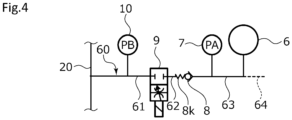
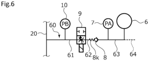
- the branch oil passage 60 is formed of oil passages 61, 62, 63, and 64. Specifically, in the branch oil passage 60, the oil passage 61, the proportional electromagnetic throttle valve 9, the oil passage 62, the check valve 8, the oil passage 63, the accumulator 6, and the oil passage 64 are connected to each other in order from a main oil passage 20 side.
- the oil passage 64 is connected to the head chamber 5-1 of the hydraulic cylinder 5 through a check valve 65 and through a switching valve (not illustrated). Accordingly, the accumulator 6 can accumulate the hydraulic oil delivered from the head chamber 5-1, according to a contraction operation of the hydraulic cylinder 5.
- accumulation means for the accumulator 6 may be, for example, a hydraulic pump other than the hydraulic cylinder 5.
- the proportional electromagnetic throttle valve 9 is connected to the controller C through an electric signal line 11. As illustrated in FIG. 2 , in a state where a signal is not input from the controller C, the proportional electromagnetic throttle valve 9 is in a closed state where the oil passages 61 and 62 do not communicate with each other. In addition, in a state where a signal is input from the controller C, the proportional electromagnetic throttle valve 9 is in an open state where the oil passages 61 and 62 communicate with each other. In addition, when the proportional electromagnetic throttle valve 9 is in an open state, the signal input from the controller C is large, for example, the higher the voltage is, the further the opening degree increases in a quadratic curve shape.
- the second pressure detector 10 is disposed in the oil passage 61 that connects the main oil passage 20 and the proportional electromagnetic throttle valve 9.
- the first pressure detector 7 is disposed in the oil passage 63 that connects the check valve 8 and the accumulator 6.
- the first pressure detector 7 is connected to the controller C through an electric signal line 12.
- the first pressure detector 7 transmits a detected pressure PA signal on an accumulator 6 side to the controller C.
- the second pressure detector 10 is connected to the controller C through an electric signal line 13.
- the second pressure detector 10 transmits a detected pressure PB signal on a main oil passage 20 side to the controller C.
- the controller C is connected to a flow rate control unit of the hydraulic pump 2 through an electric signal line 14.
- the controller C can adjust the amount of delivery of the hydraulic pump 2.
- the controller C is connected to a control unit of the drive mechanism 1 for the hydraulic pump 2 through an electric signal line 15.
- a drive source that actuates the hydraulic cylinder 5 is the hydraulic pump 2 alone, the accumulator 6 alone, or the hydraulic pump 2 and the accumulator 6 in cooperation with each other.
- the hydraulic pump 2 and the accumulator 6 are cooperated to extend the hydraulic cylinder 5 will be described with reference to FIGS. 1 to 5 .
- the switching valve 3 is switched to the extension position 3E at a time t1. Accordingly, as indicated by a solid line in FIG. 3 , the hydraulic oil is delivered from the hydraulic pump 2 to the hydraulic cylinder 5 at a substantially constant flow rate Q1. Incidentally, driving conditions of the hydraulic pump 2 do not change around time t1, and the hydraulic oil from the hydraulic pump 2 is delivered to the tank T through the oil passage 30 before time t1.
- the controller C determines that a pressure PA on the accumulator 6 side is larger than a value obtained by adding a predetermined pressure ⁇ to a pressure PB on the main oil passage 20 side (i.e., PA > PB + ⁇ ) after the switching valve 3 is switched to the extension position 3E, the controller C determines that the accumulator 6 can be used.
- the controller C When the accumulator 6 can be used, the controller C outputs a signal to reduce the flow rate of the hydraulic pump 2 to a target flow rate Q2, based on a pressure difference ⁇ PAB between the pressure PA and the pressure PB and on a load L of the hydraulic cylinder 5, and outputs a signal to open the proportional electromagnetic throttle valve 9.
- the amount of delivery of the hydraulic pump 2 gradually decreases with time according to a response characteristic of the hydraulic pump 2. Then, the amount of delivery of the hydraulic pump 2 is the substantially constant flow rate Q2 after time t3 that the amount of delivery has reached the target flow rate Q2.
- the controller C switches the proportional electromagnetic throttle valve 9 from a closed state illustrated in FIG. 4 to a throttled open state (hereinafter, simply referred to as an open state) illustrated in FIG. 5 .
- the opening degree of the proportional electromagnetic throttle valve 9 at this time is adjusted according to a reduced flow rate of the hydraulic pump 2 and to the pressure difference ⁇ PAB.
- an opening area of the proportional electromagnetic throttle valve 9 may be determined such that even after time t2, the pressure PB on the main oil passage 20 side is kept at substantially the same constant pressure as between times t1 and t2.
- a method for supplying the hydraulic oil from the accumulator 6 at the flow rate corresponding to the reduced flow rate of the hydraulic pump 2 is not limited to keeping the pressure PB on the main oil passage 20 side substantially constant, and an opening area of the proportional electromagnetic throttle valve 9 may be determined using the response characteristic of the hydraulic pump 2 stored in advance.
- the flow rate to be supplied to the main oil passage 20 is accurately controllable by controlling the opening area of the proportional electromagnetic throttle valve 9 according to an actuated state of the hydraulic pump 2 as described above.
- the hydraulic oil is delivered from the accumulator 6 to the main oil passage 20 through the oil passage 63, the check valve 8, the oil passage 62, the proportional electromagnetic throttle valve 9, and the oil passage 61.
- the controller C outputs a signal to return the flow rate of the hydraulic pump 2 to the target flow rate Q1, and outputs a signal to reduce the opening area of the proportional electromagnetic throttle valve 9 so as to close the proportional electromagnetic throttle valve 9.
- the opening area of the proportional electromagnetic throttle valve 9 is reduced to supply a flow rate corresponding to the response characteristic of the hydraulic pump 2. Accordingly, even after time t4, the pressure PB on the main oil passage 20 side can be kept substantially constant as between times t1 and t4. Then, at a time t5, the proportional electromagnetic throttle valve 9 is in a closed state illustrated in FIG. 4 .
- the amount of the hydraulic oil delivered from the accumulator 6 to the main oil passage 20 side is adjusted as indicated by diagonal hatching in FIG. 3 . Accordingly, as indicated by the solid line in FIG. 3 , the amount and the pressure PB of the hydraulic oil delivered to the hydraulic cylinder 5 are substantially the same as the amount and the pressure PB of the hydraulic oil when the hydraulic oil is delivered only by the hydraulic pump 2.
- the amount of delivery from the accumulator 6 to the main oil passage 20 side is arbitrarily controllable by adjusting the opening degree of the proportional electromagnetic throttle valve 9 based on pressures detected by the pressure detectors 7 and 10. For this reason, for example, compared to a configuration in which an opening and closing valve is provided instead of the proportional electromagnetic throttle valve 9, when the proportional electromagnetic throttle valve 9 is switched, a large amount of the hydraulic oil does not flow into the main oil passage 20. Accordingly, it is possible to prevent an abnormality such as shock caused by a rapid change in the operation speed of the hydraulic cylinder 5, so that the hydraulic cylinder 5 can be smoothly operated.
- the hydraulic oil on the main oil passage 20 side may flow into the oil passage 61 due to a flow on the main oil passage 20 side, pulsation of the hydraulic oil delivered from the hydraulic pump 2, or the like; however, as illustrated in FIG. 6 , the check valve 8 is closed, so that the hydraulic oil on the main oil passage 20 side is prevented from flowing into the accumulator 6 side.
- the check valve 8 since a biasing force of a spring 8k that biases a valve body in a closing direction acts on the check valve 8, the check valve 8 is reliably closed.
- the above-described control when the controller C causes the hydraulic pump 2 and the accumulator 6 to cooperate with each other is an example, and may be changed as appropriate.
- the check valve 8 is disposed between the pressure detectors 7 and 10, and when a pressure difference between a pressure on the accumulator 6 side in the oil passage 63 and a pressure on a hydraulic pump 2 side in the oil passage 62 with respect to the check valve 8 is small, a flow from the oil passage 63 to the oil passage 62 is stopped by the check valve 8, so that a subtle fluctuation of the hydraulic oil can be prevented from acting on the first pressure detector 7, and detection accuracy thereof can be improved.
- the check valve 8 is disposed between the proportional electromagnetic throttle valve 9 and the first pressure detector 7. For this reason, when the proportional electromagnetic throttle valve 9 is switched from a closed state to an open state or from an open state to a closed state, even in a case where a pressure fluctuation or pressure loss occurs due to the switching operation, a pressure difference between the accumulator 6 side and a proportional electromagnetic throttle valve 9 side of the check valve 8 does not reach a pressure difference enough to open the check valve 8, so that the pressure fluctuation or pressure loss can be prevented from affecting the first pressure detector 7.
- a fluid circuit according to a second embodiment of the present invention will be described with reference to FIG. 7 . Incidentally, descriptions of the same duplicate configurations as the configurations of the first embodiment will be omitted.
- a branch oil passage 160 as a branch flow passage of the fluid circuit is formed of oil passages 161, 162, 163, and 64.
- the oil passage 161, the check valve 8, the oil passage 162, the proportional electromagnetic throttle valve 9, the oil passage 163, the accumulator 6, and the oil passage 64 are connected to each other in order from a main oil passage 20 side.
- the second pressure detector 10 is disposed in the oil passage 161
- the first pressure detector 7 is disposed in the oil passage 163.
- the configuration has been described in which the working fluid is oil; however, the present invention is not limited to the configuration, and the working fluid may be a fluid or may be changed as appropriate.
- the configuration has been described in which the hydraulic pump is driven before and after a series of work to perform an extension operation of the hydraulic cylinder, and the amount of the hydraulic oil per unit time delivered from the hydraulic pump is substantially constant; however, the present invention is not limited to the configuration, and the drive amount of the hydraulic pump may be increased after a command for an extension operation is received, for example, the hydraulic pump may be operable from a stopped state, or may be changed in state from a low-load operation state to a high-load operation state.
- the configuration has been described in which the check valve is disposed between the first pressure detector and the second pressure detector; however, the present invention is not limited to the configuration, and the check valve may be disposed between the main oil passage and the second pressure detector.
- the configuration has been described in which one check valve is disposed between the proportional electromagnetic throttle valve and the first pressure detector or between the proportional electromagnetic throttle valve and the second pressure detector; however, the present invention is not limited to the configuration, and a plurality of the check valves may be disposed in the branch oil passage.
- the check valves may be disposed between the proportional electromagnetic throttle valve and the first pressure detector and between the proportional electromagnetic throttle valve and the second pressure detector, or may be disposed between the first pressure detector and the second pressure detector and at other locations in the branch oil passage.
Landscapes
- Engineering & Computer Science (AREA)
- Physics & Mathematics (AREA)
- Fluid Mechanics (AREA)
- Mechanical Engineering (AREA)
- General Engineering & Computer Science (AREA)
- Fluid-Pressure Circuits (AREA)
Applications Claiming Priority (2)
| Application Number | Priority Date | Filing Date | Title |
|---|---|---|---|
| JP2021059972 | 2021-03-31 | ||
| PCT/JP2022/012344 WO2022209967A1 (ja) | 2021-03-31 | 2022-03-17 | 流体回路 |
Publications (2)
| Publication Number | Publication Date |
|---|---|
| EP4317704A1 true EP4317704A1 (de) | 2024-02-07 |
| EP4317704A4 EP4317704A4 (de) | 2025-02-26 |
Family
ID=83458749
Family Applications (1)
| Application Number | Title | Priority Date | Filing Date |
|---|---|---|---|
| EP22780186.7A Pending EP4317704A4 (de) | 2021-03-31 | 2022-03-17 | Fluidkreislauf |
Country Status (5)
| Country | Link |
|---|---|
| US (1) | US12565902B2 (de) |
| EP (1) | EP4317704A4 (de) |
| JP (2) | JPWO2022209967A1 (de) |
| CN (1) | CN117043472A (de) |
| WO (1) | WO2022209967A1 (de) |
Family Cites Families (40)
| Publication number | Priority date | Publication date | Assignee | Title |
|---|---|---|---|---|
| US2938347A (en) | 1957-10-30 | 1960-05-31 | Malcolm B Sturgis | Power source for hydraulically operated devices |
| DE1528583A1 (de) | 1965-05-20 | 1970-01-29 | Stahl U Appbau Hans Leffer Gmb | Hydraulisch oder pneumatisch kontinuierlich betaetigter Kolbenantrieb mit hin- und hergehender Bewegung,insbesondere doppeltwirkender Druckuebersetzer |
| US3811795A (en) | 1973-01-12 | 1974-05-21 | Flow Research Inc | High pressure fluid intensifier and method |
| JPS58102804A (ja) | 1981-12-11 | 1983-06-18 | Nippon Pneumatic Kogyo Kk | ブ−スタ−付シリンダ−ユニツト及びこれを作動させる油圧回路 |
| JPS58191388A (ja) | 1982-04-30 | 1983-11-08 | Hitachi Metals Ltd | バルブ |
| JPH0374605A (ja) | 1989-08-16 | 1991-03-29 | Komatsu Ltd | 作業機シリンダの圧油供給装置 |
| JPH0639317B2 (ja) | 1989-09-09 | 1994-05-25 | 株式会社神戸製鋼所 | 移動式クレーンの変位抑制機構 |
| JPH0826555B2 (ja) | 1990-09-10 | 1996-03-13 | 株式会社小松製作所 | 作業機の位置エネルギー回収・活用装置 |
| JPH04366001A (ja) | 1991-06-12 | 1992-12-17 | Hitachi Constr Mach Co Ltd | 油圧駆動式高圧流体発生装置 |
| GB2275969B (en) | 1993-03-01 | 1997-09-17 | Europ Gas Turbines Ltd | Hydraulic intensifier |
| JPH0777205A (ja) | 1993-09-10 | 1995-03-20 | Shin Caterpillar Mitsubishi Ltd | 増圧装置 |
| US5706657A (en) | 1996-04-12 | 1998-01-13 | Caterpillar Inc. | Ride control system with an auxiliary power source |
| JP3206465B2 (ja) | 1996-12-18 | 2001-09-10 | 三菱自動車工業株式会社 | 減速エネルギー回生装置 |
| JP3238140B2 (ja) | 1999-05-19 | 2001-12-10 | ヒロタカ精機株式会社 | カム同調装置 |
| US6526747B2 (en) | 2000-01-25 | 2003-03-04 | Hitachi Construction Machinery Co., Ltd. | Hydraulic driving device |
| JP2003013904A (ja) | 2001-06-27 | 2003-01-15 | Karasawa Fine Ltd | 増圧装置 |
| JP2008185182A (ja) | 2007-01-31 | 2008-08-14 | Shin Caterpillar Mitsubishi Ltd | 作業機械における油圧制御システム |
| JP2008190694A (ja) | 2007-02-07 | 2008-08-21 | Komatsu Ltd | オートデセル制御機能を備えた制御装置及びその制御方法 |
| GB2461061A (en) | 2008-06-19 | 2009-12-23 | Vetco Gray Controls Ltd | Subsea hydraulic intensifier with supply directional control valves electronically switched |
| JP5257385B2 (ja) | 2010-03-11 | 2013-08-07 | トヨタ自動車株式会社 | 油圧制御装置 |
| US9279236B2 (en) * | 2012-06-04 | 2016-03-08 | Caterpillar Inc. | Electro-hydraulic system for recovering and reusing potential energy |
| US9051944B2 (en) * | 2012-06-15 | 2015-06-09 | Caterpillar Inc. | Hydraulic system and control logic for collection and recovery of energy in a double actuator arrangement |
| JP5985907B2 (ja) | 2012-07-04 | 2016-09-06 | イーグル工業株式会社 | 流体圧制御装置 |
| EP2728242B1 (de) * | 2012-11-05 | 2021-08-25 | Magna Steyr Fahrzeugtechnik AG & Co KG | Druckspeichersystem und Verfahren zum Betreiben eines Druckspeichersystems |
| KR20140094325A (ko) | 2013-01-22 | 2014-07-30 | (주) 티피씨 메카트로닉스 | 압력 부스터의 메인에어 급기용 바이패스 장치 |
| JP6112559B2 (ja) * | 2013-11-06 | 2017-04-12 | キャタピラー エス エー アール エル | 流体圧回路および作業機械 |
| US9926947B2 (en) | 2014-05-09 | 2018-03-27 | Montana Hydraulics, LLC | Air-to-hydraulic fluid pressure amplifier |
| JP6304881B2 (ja) | 2014-06-26 | 2018-04-04 | イーグル工業株式会社 | アキュムレータを備えた流体回路の制御装置 |
| JP6205339B2 (ja) * | 2014-08-01 | 2017-09-27 | 株式会社神戸製鋼所 | 油圧駆動装置 |
| DE102014215567A1 (de) | 2014-08-06 | 2016-02-11 | Robert Bosch Gmbh | Hydrostatischer Antrieb |
| JP6532081B2 (ja) * | 2015-04-21 | 2019-06-19 | キャタピラー エス エー アール エル | 流体圧回路および作業機械 |
| JP6567989B2 (ja) | 2016-02-26 | 2019-08-28 | イーグル工業株式会社 | 液圧装置 |
| US10247206B2 (en) | 2016-12-22 | 2019-04-02 | Eagle Industry Co., Ltd. | Fluid circuit |
| EP3581809B1 (de) * | 2017-02-10 | 2023-08-16 | Eagle Industry Co., Ltd. | Flüssigkeitsdruckkreis |
| EP3604827B1 (de) | 2017-03-29 | 2023-09-20 | Hitachi Construction Machinery Co., Ltd. | Arbeitsmaschine |
| JP6932560B2 (ja) | 2017-06-09 | 2021-09-08 | イーグル工業株式会社 | 流量制御装置及びシステム |
| JP6785203B2 (ja) | 2017-09-11 | 2020-11-18 | 日立建機株式会社 | 建設機械 |
| US10920795B2 (en) * | 2018-11-23 | 2021-02-16 | The Boeing Company | Bootstrap hydraulic reservoir |
| US12281663B2 (en) | 2021-03-31 | 2025-04-22 | Eagle Industry Co., Ltd. | Fluid circuit |
| EP4317705A4 (de) | 2021-03-31 | 2025-03-05 | Eagle Industry Co., Ltd. | Fluidkreislauf |
-
2022
- 2022-03-17 US US18/284,248 patent/US12565902B2/en active Active
- 2022-03-17 JP JP2023510944A patent/JPWO2022209967A1/ja active Pending
- 2022-03-17 CN CN202280023912.3A patent/CN117043472A/zh active Pending
- 2022-03-17 EP EP22780186.7A patent/EP4317704A4/de active Pending
- 2022-03-17 WO PCT/JP2022/012344 patent/WO2022209967A1/ja not_active Ceased
-
2025
- 2025-07-10 JP JP2025116667A patent/JP2025133927A/ja active Pending
Also Published As
| Publication number | Publication date |
|---|---|
| US12565902B2 (en) | 2026-03-03 |
| CN117043472A (zh) | 2023-11-10 |
| JP2025133927A (ja) | 2025-09-11 |
| US20240167488A1 (en) | 2024-05-23 |
| EP4317704A4 (de) | 2025-02-26 |
| WO2022209967A1 (ja) | 2022-10-06 |
| JPWO2022209967A1 (de) | 2022-10-06 |
Similar Documents
| Publication | Publication Date | Title |
|---|---|---|
| US10184228B2 (en) | Hydraulic driving device of work machine | |
| US6837045B2 (en) | Electrohydraulic lifting control device for industrial trucks | |
| US11371535B2 (en) | Fluid pressure circuit | |
| US10677274B2 (en) | Hydraulic excavator drive system | |
| US11225983B2 (en) | Fluid circuit | |
| JP6509651B2 (ja) | 流体回路 | |
| US10247206B2 (en) | Fluid circuit | |
| US12326741B2 (en) | Counter pressure valve arrangement | |
| US12292060B2 (en) | Fluid circuit | |
| US6295810B1 (en) | Hydrostatic drive system | |
| EP4317704A1 (de) | Fluidkreislauf | |
| US12247595B2 (en) | Hydraulic circuit with combined compensation and energy recovery function | |
| EP4624766A1 (de) | Hydraulischer druckkreislauf | |
| JP6605413B2 (ja) | 作業機械の油圧駆動装置 | |
| EP4624765A1 (de) | Hydraulischer druckkreislauf | |
| EP4484761A1 (de) | Flüssigkeitsdruckkreislauf | |
| US20250180043A1 (en) | Fluid pressure circuit | |
| WO2026004615A1 (ja) | 流体圧回路 |
Legal Events
| Date | Code | Title | Description |
|---|---|---|---|
| STAA | Information on the status of an ep patent application or granted ep patent |
Free format text: STATUS: THE INTERNATIONAL PUBLICATION HAS BEEN MADE |
|
| PUAI | Public reference made under article 153(3) epc to a published international application that has entered the european phase |
Free format text: ORIGINAL CODE: 0009012 |
|
| STAA | Information on the status of an ep patent application or granted ep patent |
Free format text: STATUS: REQUEST FOR EXAMINATION WAS MADE |
|
| 17P | Request for examination filed |
Effective date: 20231009 |
|
| AK | Designated contracting states |
Kind code of ref document: A1 Designated state(s): AL AT BE BG CH CY CZ DE DK EE ES FI FR GB GR HR HU IE IS IT LI LT LU LV MC MK MT NL NO PL PT RO RS SE SI SK SM TR |
|
| DAV | Request for validation of the european patent (deleted) | ||
| DAX | Request for extension of the european patent (deleted) | ||
| A4 | Supplementary search report drawn up and despatched |
Effective date: 20250128 |
|
| RIC1 | Information provided on ipc code assigned before grant |
Ipc: F15B 1/02 20060101AFI20250122BHEP |