EP4318009A1 - Dispositif et procédé de surveillance d'état de batterie, et dispositif de protection de batterie - Google Patents
Dispositif et procédé de surveillance d'état de batterie, et dispositif de protection de batterie Download PDFInfo
- Publication number
- EP4318009A1 EP4318009A1 EP22904426.8A EP22904426A EP4318009A1 EP 4318009 A1 EP4318009 A1 EP 4318009A1 EP 22904426 A EP22904426 A EP 22904426A EP 4318009 A1 EP4318009 A1 EP 4318009A1
- Authority
- EP
- European Patent Office
- Prior art keywords
- current value
- current
- channel
- current sensor
- average
- Prior art date
- Legal status (The legal status is an assumption and is not a legal conclusion. Google has not performed a legal analysis and makes no representation as to the accuracy of the status listed.)
- Granted
Links
Images



Classifications
-
- G—PHYSICS
- G01—MEASURING; TESTING
- G01R—MEASURING ELECTRIC VARIABLES; MEASURING MAGNETIC VARIABLES
- G01R31/00—Arrangements for testing electric properties; Arrangements for locating electric faults; Arrangements for electrical testing characterised by what is being tested not provided for elsewhere
- G01R31/36—Arrangements for testing, measuring or monitoring the electrical condition of accumulators or electric batteries, e.g. capacity or state of charge [SoC]
-
- G—PHYSICS
- G01—MEASURING; TESTING
- G01R—MEASURING ELECTRIC VARIABLES; MEASURING MAGNETIC VARIABLES
- G01R31/00—Arrangements for testing electric properties; Arrangements for locating electric faults; Arrangements for electrical testing characterised by what is being tested not provided for elsewhere
- G01R31/36—Arrangements for testing, measuring or monitoring the electrical condition of accumulators or electric batteries, e.g. capacity or state of charge [SoC]
- G01R31/392—Determining battery ageing or deterioration, e.g. state of health
-
- G—PHYSICS
- G01—MEASURING; TESTING
- G01R—MEASURING ELECTRIC VARIABLES; MEASURING MAGNETIC VARIABLES
- G01R31/00—Arrangements for testing electric properties; Arrangements for locating electric faults; Arrangements for electrical testing characterised by what is being tested not provided for elsewhere
- G01R31/36—Arrangements for testing, measuring or monitoring the electrical condition of accumulators or electric batteries, e.g. capacity or state of charge [SoC]
- G01R31/382—Arrangements for monitoring battery or accumulator variables, e.g. SoC
-
- G—PHYSICS
- G01—MEASURING; TESTING
- G01R—MEASURING ELECTRIC VARIABLES; MEASURING MAGNETIC VARIABLES
- G01R19/00—Arrangements for measuring currents or voltages or for indicating presence or sign thereof
- G01R19/003—Measuring mean values of current or voltage during a given time interval
-
- G—PHYSICS
- G01—MEASURING; TESTING
- G01R—MEASURING ELECTRIC VARIABLES; MEASURING MAGNETIC VARIABLES
- G01R19/00—Arrangements for measuring currents or voltages or for indicating presence or sign thereof
- G01R19/0038—Circuits for comparing several input signals and for indicating the result of this comparison, e.g. equal, different, greater, smaller (comparing pulses or pulse trains according to amplitude)
-
- G—PHYSICS
- G01—MEASURING; TESTING
- G01R—MEASURING ELECTRIC VARIABLES; MEASURING MAGNETIC VARIABLES
- G01R19/00—Arrangements for measuring currents or voltages or for indicating presence or sign thereof
- G01R19/0092—Measuring current only
-
- G—PHYSICS
- G01—MEASURING; TESTING
- G01R—MEASURING ELECTRIC VARIABLES; MEASURING MAGNETIC VARIABLES
- G01R31/00—Arrangements for testing electric properties; Arrangements for locating electric faults; Arrangements for electrical testing characterised by what is being tested not provided for elsewhere
- G01R31/28—Testing of electronic circuits, e.g. by signal tracer
- G01R31/282—Testing of electronic circuits specially adapted for particular applications not provided for elsewhere
- G01R31/2827—Testing of electronic protection circuits
-
- G—PHYSICS
- G01—MEASURING; TESTING
- G01R—MEASURING ELECTRIC VARIABLES; MEASURING MAGNETIC VARIABLES
- G01R31/00—Arrangements for testing electric properties; Arrangements for locating electric faults; Arrangements for electrical testing characterised by what is being tested not provided for elsewhere
- G01R31/28—Testing of electronic circuits, e.g. by signal tracer
- G01R31/282—Testing of electronic circuits specially adapted for particular applications not provided for elsewhere
- G01R31/2829—Testing of circuits in sensor or actuator systems
-
- G—PHYSICS
- G01—MEASURING; TESTING
- G01R—MEASURING ELECTRIC VARIABLES; MEASURING MAGNETIC VARIABLES
- G01R35/00—Testing or calibrating of apparatus covered by the other groups of this subclass
-
- H—ELECTRICITY
- H02—GENERATION; CONVERSION OR DISTRIBUTION OF ELECTRIC POWER
- H02H—EMERGENCY PROTECTIVE CIRCUIT ARRANGEMENTS
- H02H7/00—Emergency protective circuit arrangements specially adapted for specific types of electric machines or apparatus or for sectionalised protection of cable or line systems, and effecting automatic switching in the event of an undesired change from normal working conditions
- H02H7/18—Emergency protective circuit arrangements specially adapted for specific types of electric machines or apparatus or for sectionalised protection of cable or line systems, and effecting automatic switching in the event of an undesired change from normal working conditions for batteries; for accumulators
Definitions
- the present invention relates to an apparatus and a method for monitoring battery state, and an apparatus for protecting a battery, and more particularly, to an apparatus and a method for monitoring battery state, and an apparatus for protecting a battery by measuring and monitoring current using different types of current sensors, thereby protecting the battery from abnormal current even when any one current sensor fails.
- lithium secondary batteries are in the limelight because of their advantages of free charge and discharge, very low self-discharge rate, and high energy density because they hardly have a memory effect compared to nickel-based secondary batteries.
- a battery protection device may generally have a current sensor for measuring current.
- the current sensor monitors a state of a battery by measuring current flowing in a charging/discharging path of the battery and detects overcurrent flowing in a battery pack.
- the current measured by the current sensor may be used as information for calculating State of Charge (SOC) or may be used as a basis for determining whether a charge/discharge process is normally performed.
- SOC State of Charge
- an object of the present invention is to provide a battery state monitoring apparatus with high-efficiency, high-stability and high-reliability.
- another object of the present invention is to provide a battery state monitoring method with high-efficiency, high-stability and high-reliability.
- the other object of the present invention is to provide a battery protection apparatus with high-efficiency, high-stability and high-reliability.
- an apparatus for monitoring battery state may comprise: a first current sensor connected to a positive terminal of a battery to measure a first current value; a second current sensor connected to a negative terminal of the battery to measure a second current value; and a controller configured to set a representative current value among the first current value and the second current value according to whether at least one of the first current sensor and the second current sensor is out of order and to monitor the representative current value.
- the first current sensor is of a different type from the second current sensor.
- the controller may be configured to: apply power to the first current sensor and the second current sensor to measure a first average current value and a second average current value, respectively; determine whether the first current sensor is out of order based on the first average current value; and determine whether the second current sensor is out of order based on the second average current value.
- the controller may further be configured to compare the first average current value with a specific threshold value to determine whether the first current sensor is out of order.
- the controller may further be configured to determine that the first current sensor is out of order when a CAN signal transmitted periodically from the first current sensor is not received.
- the controller may further be configured to determine that the first current sensor is out of order when an error message is received among CAN signals periodically transmitted from the first current sensor.
- the first current sensor may include a flux type current sensor.
- the second current sensor may include a hall type two-channel current sensor including a first channel and a second channel.
- the controller may further be configured to: calculate an average current value in the first channel and an average current value in the second channel, separately; compare the average current value in the first channel and the average current value in the second channel with a current specification of the first channel.
- the controller may further be configured to: upon the average current value in the first channel and the average current value in the second channel being greater than or equal to the current specification of the first channel, compare the average current value in the second channel with a current specification of the second channel.
- the controller may further be configured to: determine that the second current sensor is out of order in the instance that the average current value in the second channel is greater than the current specification in the second channel; and set the average current value in the second channel as the representative current value of the second current sensor in the instance that the average current value in the second channel is less than or equal to the current specification of the second channel.
- the controller may further be configured to: in the instance that at least one of the average current value in the first channel and the average current value in the second channel is smaller than the current specification of the first channel and a difference of the average current value in the first channel and the average current value in the second channel is equal to or less than a specific threshold value, set the average current value in the first channel as the representative current value of the second current sensor.
- the controller may further be configured to: in the instance that at least one of the average current value in the first channel and the average current value in the second channel is smaller than the current specification in the first channel, and a difference between the average current value in the first channel and the average current value in the second channel exceeds a specific threshold value, determine that the second current sensor is out of order.
- the controller may further be configured to: in the instance that the first current sensor and the second current sensor are determined to be normal, calculate a difference between the first average current value and the second average current value; output a first average current value as a representative current value in the instance that the difference is less than a specific threshold; determine that a current measurement error of the battery has occurred in the instance that the difference exceeds a specific threshold value.
- the controller may further be configured to output the first average current value as a representative current value when it is determined that the first current sensor is normal and the second current sensor is out of order.
- the controller may further be configured to output the second average current value as a representative current value when it is determined that the first current sensor is out of order and the second current sensor is normal.
- the controller is configured to determine that a current measurement error of the battery has occurred when it is determined that the first current sensor and the second current sensor are out of order.
- the apparatus for monitoring battery state is applied to a battery protection apparatus that protects the battery by controlling a contactor in the instance that the representative current value is greater than or equal to a specific threshold value.
- a battery protection apparatus may comprise: a first current sensor connected to a positive terminal of a battery to measure a first current value; a second current sensor connected to a negative terminal of the battery to measure a second current value; a contactor including a first contactor positioned between the positive terminal of the battery and the first current sensor and a second contactor positioned between the negative terminal of the battery and the second current sensor; and a controller configured to set a representative current value among the first current value and the second current value, and determine whether the representative current value is an abnormal current, wherein the controller compares the representative current value with a specific threshold value to determine whether the representative current value is an abnormal current and controls the contactor to protect the battery according to whether or not the representative current value is an abnormal current.
- a method for monitoring battery state by setting a representative current value among a first current value and a second current value depending on whether at least one of the first current sensor for measuring the first current value and the second current sensor for measuring the second current value is out of order wherein the first current sensor is connected to a positive terminal of a battery and the second current sensor connected to a negative terminal of the battery, the method may comprise: calculating a first average current value and a second average current value, respectively, by applying power to the first current sensor and the second current sensor; determining whether the first current sensor is out of order based on the first average current value; determining whether the second current sensor is out of order based on the second average current value; and setting a current value of any one of the first current sensor and the second current sensor that normally operates as a representative current value to monitor the battery.
- the determining whether the first current sensor is out of order based on the first average current value may include comparing the first average current value with a specific threshold value to determine whether the first current sensor is out of order.
- the first current sensor may include a flux type current sensor.
- the second current sensor may include a hall type two-channel current sensor including a first channel and a second channel.
- the calculating a first average current value and a second average current value, respectively, by applying power to the first current sensor and the second current sensor may include calculating the first average current value of the first current values measured a plurality of times by the first current sensor; and calculating an average current value in the first channel and an average current value in the second channel in the second current sensor, separately.
- the determining whether the second current sensor is out of order based on the second average current value may include comparing the average current value in the first channel and the average current value in the second channel with a current specification of the first channel.
- the comparing the average current value in the first channel and the average current value in the second channel with a current specification of the first channel may include: upon the average current value in the first channel and the average current value in the second channel being greater than or equal to the current specification of the first channel, comparing the average current value in the second channel with a current specification of the second channel.
- the comparing the average current value in the second channel with a current specification of the second channel may include: determining that the second current sensor is out of order in the instance that the average current value in the second channel is greater than the current specification in the second channel; and setting the average current value in the second channel as the representative current value of the second current sensor in the instance that the average current value in the second channel is less than or equal to the current specification of the second channel.
- the comparing the average current value in the first channel and the average current value in the second channel with a current specification of the first channel may include: in the instance that at least one of the average current value in the first channel and the average current value in the second channel is smaller than the current specification of the first channel and a difference between the average current value in the first channel and the average current value in the second channel is less than or equal to a specific threshold value, setting the average current value in the first channel as the representative current value of the second current sensor.
- the comparing the average current value in the first channel and the average current value in the second channel with a current specification of the first channel may include: in the instance that at least one of the average current value in the first channel and the average current value in the second channel is smaller than the current specification of the first channel and a difference between the average current value in the first channel and the average current value in the second channel exceeds a specific threshold value, determining that the second current sensor is out of order.
- the setting a current value of any one of the first current sensor and the second current sensor that normally operates as a representative current value to monitor the battery may include: calculating a difference between the first average current value and the second average current value in the instance that the first current sensor and the second current sensor are determined to be normal; outputting a first average current value as a representative current value in the instance that the difference is equal to or less than a specific threshold; and determining that a current measurement error of the battery has occurred in the instance that the difference exceeds a specific threshold value.
- the setting a current value of any one of the first current sensor and the second current sensor that normally operates as a representative current value to monitor the battery may include outputting the first average current value as a representative current value when it is determined that the first current sensor is normal and the second current sensor is out of order.
- the setting a current value of any one of the first current sensor and the second current sensor that normally operates as a representative current value to monitor the battery may include outputting the second average current value as a representative current value when it is determined that the first current sensor is out of order and the second current sensor is normal.
- the method for monitoring battery may further comprise determining and outputting that a current measurement error of the battery has occurred when it is determined that the first current sensor and the second current sensor are out of order.
- the battery state monitoring apparatus and method, and the battery protection apparatus may comprise a first current sensor connected to a positive terminal of a battery to measure a first current value; a second current sensor connected to a negative terminal of the battery to measure a second current value; a contactor including a first contactor positioned between the positive terminal of the battery and the first current sensor and a second contactor positioned between the negative terminal of the battery and the second current sensor; and a controller configured to set a representative current value among the first current value and the second current value, and determine whether the representative current value is an abnormal current, and thus, it is possible to measure battery current stably even when one current sensor fails by measuring and monitoring current using heterogeneous current sensors, and protect the battery from abnormal current based on the representative current value of the battery, thereby providing high-efficiency, high-stability and high-reliability battery state monitoring apparatus and method, and a battery protection apparatus.
- first, second, A, B, and the like may be used herein to describe various elements, these elements should not be limited by these terms. These terms are only used to distinguish one element from another. For example, a first element could be termed a second element, and, similarly, a second element could be termed a first element, without departing from the scope of the present invention.
- the term "and/or" includes combinations of a plurality of associated listed items or any of the plurality of associated listed items.
- FIG. 1 is a block diagram of a conventional battery protection unit.
- a conventional battery protection unit (BPU) is connected to at least one battery and electrically protects the battery from abnormal currents.
- a conventional battery protection device (unit) is provided with one current sensor.
- the current sensor is provided in a noncontact type and wrapped around a bus bar connecting the battery and the contactor, so that one end of the current sensor may be located at a positive end of the battery.
- the current sensor is not limited to the description, and may be provided in any form capable of electrically protecting the battery from abnormal current.
- a current sensor protects a battery by detecting an overcurrent occurrence.
- the conventional battery protection device provides only one current sensor, and thus, it is difficult to detect an abnormal current or a fault current when the current sensor fails, thereby not preventing damage to the battery.
- the present invention provides a battery protection apparatus and a method for preventing damage to a battery due to a failure of a current sensor by using different types of current sensors, which will be described hereinafter.
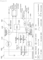
- FIG. 2 is a configuration diagram of a battery protection apparatus according to embodiments of the present invention.
- a battery protection apparatus (BPU) according to embodiments of the present invention, as described above, is connected to at least one battery and electrically protects the battery from abnormal current such as overcurrent.
- the battery may be a battery module or a battery rack.
- the battery module has a configuration in which a plurality of battery cells (cells), which are the minimum units of the battery, are combined in series and parallel, and the battery rack may include a plurality of battery modules.
- the battery protection apparatus may include a battery state monitoring unit, a contactor (Main Contactor; MC, 4000), and a fuse 5000, the battery state monitoring apparatus including a first current sensor 1000, a second current sensor 2000, a controller 3000.
- the battery state monitoring unit may also be provided as a separate device including the first current sensor 1000, the second current sensor 2000, and the controller 3000.
- the fuse 5000 in the battery protection apparatus (BPU) may not necessarily be used.
- the first current sensor 1000 and the second current sensor 2000 may be devices for detecting abnormal currents such as overcurrent generated in the battery.
- the first current sensor 1000 may be connected to a positive terminal of the battery.
- one end of the first current sensor 1000 may be connected to the other end side of the first contactor 3100 to be described later, and the other end of the first current sensor 1000 may be connected to a positive terminal of a DC link.
- the first current sensor 1000 may be a flux type current sensor.
- the first current sensor 1000 may transmit a measurement value to the controller 3000 to be described later using CAN communication.
- the measured value of the first current sensor 1000 may be provided as a current value or a voltage value.
- the detection accuracy of the first current sensor 1000 may be higher than that of the second current sensor 2000 to be described later.
- the second current sensor 2000 may be located at a negative terminal side of the battery. More specifically, one end of the second current sensor 2000 may be located on a side of the other end of a second contactor 3500 to be described later, and the other end of the second current sensor 2000 may be located on a negative terminal side of a DC link.
- the second current sensor 2000 may be a different type from the first current sensor 1000.
- the battery state monitoring apparatus may include different types of current sensors.
- the second current sensor 2000 may be a hall type current sensor.
- the second current sensor 2000 may transmit measurement values to the controller 3000 to be described later.
- a measurement value of the second current sensor 2000 may be provided as a voltage measurement.
- the controller 3000 may supply power to the first current sensor 1000 and the second current sensor 2000.
- the controller 3000 may determine whether at least one of the first current sensor 1000 and the second current sensor 2000 is out of order. Accordingly, the controller 3000 may measure a magnitude of current, even when current measurement is impossible due to an error that has occurred in one sensor, using the other sensor operating normally.
- the controller 3000 may obtain the first current value measured by the first current sensor 1000 and the second current value measured by the second current sensor 2000.
- the controller 3000 may convert the obtained measurement value into a current value, analyze it, and determine whether the first current sensor 1000 and the second current sensor 2000 are out of order. Accordingly, the controller 3000 may monitor generation of abnormal current in the battery based on a current value measured by a normally operating sensor among the first current sensor 1000 and the second current sensor 2000. The operation of the controller 3000 for monitoring a state of the battery will be described in more detail using a method for monitoring a state of the battery.
- the controller 3000 may control an opening and closing operation of the contactor 4000, to be described later, according to a representative current value measured by the first and second current sensors 1000 and 2000.
- the contactor 4000 may be a bi-directional contactor.
- the controller 3000 may keep the first contactor 4100 or the second contactor 4500 closed in the instance that the representative current value measured from the first current sensor 1000 and the second current sensor 2000 is less than a certain reference, Accordingly, the battery may be charged or discharged by being connected to a charge/discharge circuit by the first contactor 4100 or the second contactor 4500.
- the controller 3000 may switch the first contactor 4100 and the second contactor 4500 to an open state, which will be described later, when the measured value of the first current sensor 1000 or the second current sensor is equal to or greater than a predetermined reference. Accordingly, the battery may be cut off from the charge/discharge circuit by the first contactor 4100 and the second contactor 4500.
- the controller 3000 may be a RBMS (Rack BMS) or may be included in the RBMS as a part of the RBMS. The operation of the controller 3000 will be described in more detail with reference to FIG. 3 below.
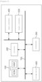
- FIG. 3 is a block diagram of a controller in a battery protection apparatus according to embodiments of the present invention.
- the controller 3000 in the battery protection apparatus may include a memory 100, a processor 200, a transceiver 300, an input interface 400, an output interface 500, and a storage device 600.
- each of the components 100, 200, 300, 400, 500, and 600 included in the controller 3000 may be connected by a bus 700 to communicate with each other.
- the memory 100 and the storage device 600 may include at least one of a volatile storage medium and a non-volatile storage medium.
- the memory 100 and the storage device 600 may include at least one of a read only memory (ROM) and a random access memory (RAM).
- the memory 100 may include at least one instruction executed by the processor 200.
- the at least one instruction may include an instruction to calculate a first average current value and a second average current value, respectively, by applying power to the first current sensor and the second current sensor; instruction to determine whether the first current sensor is out of order based on the first average current value; instruction to determine whether the second current sensor is out of order based on the second average current value; and instruction to set a current value of any one of the first current sensor and the second current sensor that normally operates as a representative current value to monitor the battery.
- the processor 200 may mean a central processing unit (CPU), a graphics processing unit (GPU), or a dedicated processor on which methods according to embodiments of the present invention are performed.
- CPU central processing unit
- GPU graphics processing unit
- dedicated processor on which methods according to embodiments of the present invention are performed.
- the processor 200 may execute at least one program command stored in the memory 100.
- the contactor 4000 of the battery protection apparatus is an electrical switchgear and can be operated as open/closed by the controller 3000 to be described later.
- the contactor 4000 may charge or discharge the battery or block charging and discharging of the battery according to a command from the controller 3000 to be described later.
- the contactor 4000 may be a magnetic contactor.
- the contactor 4000 may include a first contactor 4100 and a second contactor 4500.
- One end of the first contactor 4100 may be connected in series with the other end of the first fuse 5100 to be described later, and the other end of the first contactor 4100 may be connected in series with a positive terminal of the DC link where the first current sensor 1000 is located. In other words, the first contactor 4100 may be located between a positive terminal of the battery and the first current sensor 1000.
- one end of the second contactor 4500 may be connected in series with the other end of the second fuse 5500 to be described later, and the other end of the second contactor 4500 may be connected in series with a negative terminal of the DC link where the second current sensor 2000 is located.
- the second contactor 4500 may be positioned between a negative terminal of the battery and the second current sensor 2000.
- the first contactor 4100 and the second contactor 4500 may be provided as bi-directional contactors. Accordingly, the first contactor 4100 and the second contactor 4500 may be opened and closed by the controller 3000 according to measured values of the first current sensor 1000 or the second current sensor 2000.
- the first contactor 4100 and the second contactor 4500 may be configured to be controlled in a closed state when the measured values of the first current sensor 1000 and the second current sensor 2000 are less than a predetermined reference by the controller 3000.
- the first contactor 4100 and the second contactor 4500 may be configured to be controlled in an open state by the controller 3000 when the measured value of the first current sensor 1000 or the second current sensor 2000 exceeds a predetermined reference.
- the fuse 5000 is one of the main components of the BPU to protect the battery when a short-circuit current occurs, and may be a protection device that is passively disconnected to protect the battery when a short-circuit current occurs.
- the fuse 5000 is a disposable component that requires periodic replacement during use.
- the fuse 5000 may include a first fuse 5100 and a second fuse 5500.
- the first fuse 5100 may have one end connected to a positive terminal of the battery and the other end connected to the first contactor 4100.
- the second fuse 5500 may have one end connected to a negative terminal of the battery and the other end connected to the second contactor 4500.
- the battery protection apparatus may not necessarily use a fuse 5000.
- the battery protection apparatus has been described above. Hereinafter, a battery state monitoring method and a battery protection method performed by a controller in a battery protection device will be described.
- FIG. 4 is a operational flowchart of a battery state monitoring method in a battery protection apparatus according to embodiments of the present invention.
- the processor 200 of the controller 3000 in the battery protection apparatus may apply power to the first current sensor 1000 and the second current sensor 2000, respectively, and measure current values individually to monitor a state of the battery (S1000).
- the processor 200 may measure current values a plurality of times per second using the first current sensor 1000.
- the first current sensor 1000 may be a flux type.
- the processor 200 may measure the current values a plurality of times per second using the second current sensor 2000.
- the second current sensor 2000 may be a Hall type sensor including two channels of a fine channel and a coarse channel.
- the processor 200 may calculate an average current value of the current values of the first current sensor 1000 measured from the first current sensor 1000 and an average current value of the current values of the second current sensor 2000 measured from the second current sensor 2000, respectively (S2000).
- the processor 200 may use the first current sensor 1000 to calculate an average value of a plurality of current values calculated plurality of times per second.
- the processor 200 may use the second current sensor 2000 to respectively calculate average current values of current values for the fine channel and for the coarse channel measured multiple times per second.
- the processor 200 may determine whether the first current sensor 1000 is out of order based on the calculated average current value. In other words, it may be determined whether the first current sensor operates normally (S3000).
- the processor 200 may determine whether the first current sensor 1000 is out of order by comparing the average current value with a preset first threshold value (out of range).
- the processor 200 may determine that the first current sensor 1000 is out of order when the average current value exceeds the first threshold value.
- the first threshold value is preset and may be included in a specification of the first current sensor 1000.
- the processor 200 may perform a sensor loss of communication (LOC) diagnosis to determine whether the first current sensor 1000 is out of order.
- LOC sensor loss of communication
- the sensor LOG diagnosis may relate to determining whether the controller 3000 receives a CAN signal periodically transmitted by the first current sensor 1000. For example, in case that the first current sensor 1000 itself sends a CAN signal to the controller 3000 every 10 ms, but the controller 3000 does not receive the CAN signal, it can be determined that the first current sensor 1000 is out of order.
- an error message is received, by the controller 3000, among the CAN signals transmitted from the first current sensor 1000, the processor 2000 may determine that the first current sensor 1000 fails.
- the processor 200 may determine whether the second current sensor 2000 is out of order. Determining whether the second current sensor 2000 is out of order may be performed independently and concurrently with determining whether or not the first current sensor 1000 is out of order. The step of determining whether the second current sensor 2000 is out of order will be described in more detail with reference to FIG. 5 to be described later.
- the processor 200 may calculate a difference of an average current value of the first sensor 1000 and an average current value of the second sensor 2000.
- the processor 200 may output the average current value of the first current sensor 1000 as a representative current value (S6000). Then, the processor 200 may transmit the representative current value to the BBMS.
- the second threshold value may be a preset reference value.
- the processor 200 may transmit an operation error signal of the current sensor (S7000).
- S7000 the processor 200 may determine that an operation error of the sensor has occurred.
- the processor 200 may move to step S6000 again and set the average current value of the first current sensor 1000 as the representative current value.
- the processor 200 may determine whether the second current sensor 2000 is out of order. In other words, the processor 200 may determine whether the second current sensor operates normally (S8000).
- the processor 200 may select the second average current value of the second current sensor 2000 as the representative average value (S9000).
- the processor 200 may return to step S7000 and transmit an operation error signal of the current sensor.
- FIG. 5 is a operational flowchart illustrating a step of determining whether a second current sensor is out of order in a battery protection method according to embodiments of the present invention.
- the processor 200 may compare the average current value in the fine channel and the average current value in the coarse channel calculated in step S1000 with a third threshold value L 3 .
- the processor 200 may measure the second current value by applying power to the second current sensor 2000 in step S1000, but is not limited thereto, and may measure it after step S4000.
- the processor 200 may compare the average current value in the coarse channel with a fourth threshold value (L 4 ).
- the third threshold value L 3 may be included in a current specification (A) in the fine channel
- the fourth threshold value L 4 may be included in a current specification (A) in the coarse channel.
- the processor 200 may determine that the second current sensor 2000 is out of order (S4300).
- the processor 200 may set the average current value in the coarse channel as the representative current value of the second sensor 2000 (S4400).
- the processor 200 may determine whether the difference of average current values in the fine channel and in the coarse channel is normal.
- the cases that the average current value in the fine channel and the average current value in the coarse channel are smaller than the third threshold value (L 3 ) may include a case that the average current value in the coarse channel is less than the third threshold value (L 3 ) and the average current value in the fine channel is less than the third threshold value (L 3 ), or a case that the average current value in the coarse channel exceeds the third threshold value (L 3 ) and the average current value in the fine channel is less than the third threshold value (L 3 ), or a case where the average current value in the coarse channel is less than or equal to the third threshold value L 3 and the average current value in the fine channel exceeds the third threshold value L 3 .
- Whether the difference of average current values in the fine channel and the coarse channel is normal may be determined by comparing it with a fifth threshold value L 5 .
- the fifth threshold value L 5 may be a preset reference value.
- the processor 200 may determine that it is normal if the difference of respective average current values in the fine channel and the coarse channel is less than a fifth threshold value L 5 (S4500), set and output the average current value in the fine channel as the representative current value of second sensor 2000 (S4600).
- the processor 200 may move to step S4300 and determine that the second sensor 2000 is out of order.
- the processor 200 in the battery protection apparatus (BPU) may compare the representative current value with a specific threshold value to determine whether an abnormal current is generated in the battery.
- the processor 200 may protect the battery by controlling the contactor according to whether the abnormal current occurs.
- the battery state monitoring apparatus and method, and the battery protection apparatus may comprise a first current sensor connected to a positive terminal of a battery to measure a first current value; a second current sensor connected to a negative terminal of the battery to measure a second current value; a contactor including a first contactor positioned between the positive terminal of the battery and the first current sensor and a second contactor positioned between the negative terminal of the battery and the second current sensor; and a controller configured to set a representative current value among the first current value and the second current value, and determine whether the representative current value is an abnormal current, and thus, it is possible to measure battery current stably even when one current sensor fails by measuring and monitoring current using heterogeneous current sensors, and protect the battery from abnormal current based on the representative current value of the battery, thereby providing high-efficiency, high-stability and high-reliability battery state monitoring apparatus and method, and a battery protection apparatus.
- the operations of the method according to the embodiments of the present invention may be implemented as a computer-readable program or code on a computer-readable recording medium.
- the computer-readable recording medium includes all types of recording devices in which data readable by a computer system is stored.
- the computer-readable recording medium may be distributed in a network-connected computer system to store and execute computer-readable programs or codes in a distributed manner.
- the computer-readable recording medium may include a hardware device, such as a ROM, a RAM, and a flash memory, specially configured to store and execute program instructions.
- the program instructions may include not only machine language codes such as those generated by a compiler, but also high-level language codes that can be executed by a computer by using an interpreter or the like.
- a block or apparatus corresponds to a method step or feature of a method step.
- aspects described in the context of a method may also represent a feature of a corresponding block or item or a corresponding apparatus.
- Some or all of the method steps may be performed by (or using) a hardware device, such as, for example, a microprocessor, a programmable computer, or an electronic circuit. In some embodiments, one or more of the most important method steps may be performed by such an apparatus.
Landscapes
- Physics & Mathematics (AREA)
- General Physics & Mathematics (AREA)
- Engineering & Computer Science (AREA)
- General Engineering & Computer Science (AREA)
- Electromagnetism (AREA)
- Power Engineering (AREA)
- Secondary Cells (AREA)
- Charge And Discharge Circuits For Batteries Or The Like (AREA)
- Testing Electric Properties And Detecting Electric Faults (AREA)
- Protection Of Static Devices (AREA)
Applications Claiming Priority (2)
| Application Number | Priority Date | Filing Date | Title |
|---|---|---|---|
| KR1020210173099A KR102900683B1 (ko) | 2021-12-06 | 2021-12-06 | 배터리 상태 모니터링 장치 및 방법, 그리고 배터리 보호 장치 |
| PCT/KR2022/015268 WO2023106592A1 (fr) | 2021-12-06 | 2022-10-11 | Dispositif et procédé de surveillance d'état de batterie, et dispositif de protection de batterie |
Publications (3)
| Publication Number | Publication Date |
|---|---|
| EP4318009A1 true EP4318009A1 (fr) | 2024-02-07 |
| EP4318009A4 EP4318009A4 (fr) | 2024-12-18 |
| EP4318009B1 EP4318009B1 (fr) | 2025-09-10 |
Family
ID=86730610
Family Applications (1)
| Application Number | Title | Priority Date | Filing Date |
|---|---|---|---|
| EP22904426.8A Active EP4318009B1 (fr) | 2021-12-06 | 2022-10-11 | Dispositif et procédé de surveillance d'état de batterie, et dispositif de protection de batterie |
Country Status (8)
| Country | Link |
|---|---|
| US (1) | US20240201268A1 (fr) |
| EP (1) | EP4318009B1 (fr) |
| JP (1) | JP7679494B2 (fr) |
| KR (1) | KR102900683B1 (fr) |
| CN (1) | CN117203542A (fr) |
| ES (1) | ES3046133T3 (fr) |
| HU (1) | HUE073171T2 (fr) |
| WO (1) | WO2023106592A1 (fr) |
Families Citing this family (3)
| Publication number | Priority date | Publication date | Assignee | Title |
|---|---|---|---|---|
| KR102621865B1 (ko) | 2023-09-14 | 2024-01-05 | 주식회사 에이치에스해성 | 통합 전원 관제 및 진단 시스템 |
| KR20250060551A (ko) * | 2023-10-26 | 2025-05-07 | 삼성에스디아이 주식회사 | 배터리 전류 측정장치 및 그 방법 |
| US12578387B2 (en) * | 2024-01-04 | 2026-03-17 | Hitachi Astemo, Ltd. | Systems and methods for fault detection, diagnosis, and recovery in an electromechanical actuator |
Family Cites Families (13)
| Publication number | Priority date | Publication date | Assignee | Title |
|---|---|---|---|---|
| JP2004251625A (ja) * | 2003-02-18 | 2004-09-09 | Hioki Ee Corp | 電池用内部インピーダンス測定装置 |
| WO2008096771A1 (fr) * | 2007-02-08 | 2008-08-14 | Panasonic Ev Energy Co., Ltd. | Dispositif et procédé pour détecter une anomalie d'un dispositif de stockage électrique |
| JP2013019832A (ja) * | 2011-07-13 | 2013-01-31 | Toyota Motor Corp | 電流センサの異常検出装置および異常検出方法 |
| FR3013460B1 (fr) * | 2013-11-21 | 2018-01-05 | Commissariat A L'energie Atomique Et Aux Energies Alternatives | Procede de detection d'un dysfonctionnement d'un systeme de controle de batterie |
| CN204367903U (zh) * | 2015-01-13 | 2015-06-03 | 安徽江淮汽车股份有限公司 | 一种动力电池包 |
| JP2016207646A (ja) * | 2015-04-27 | 2016-12-08 | 株式会社リコー | 二次電池装置及び二次電池装置における制御方法 |
| US20170243413A1 (en) * | 2016-02-22 | 2017-08-24 | Hamilton Sundstrand Corporation | Method for determining aircraft sensor failure without a redundant sensor and correct sensor measurement when redundant aircraft sensors give inconsistent readings |
| EP3757594B1 (fr) * | 2018-11-02 | 2022-08-17 | LG Energy Solution, Ltd. | Appareil et procédé de diagnostic de capteur de courant |
| KR102841673B1 (ko) | 2019-07-10 | 2025-07-31 | 주식회사 엘지에너지솔루션 | 배터리 팩의 결함 검출 장치 및 방법 |
| KR102843025B1 (ko) * | 2019-12-31 | 2025-08-14 | 주식회사 아모그린텍 | 홀센서 타입 전류센서 및 그의 제조방법 |
| CN213544769U (zh) * | 2020-08-28 | 2021-06-25 | 蜂巢能源科技有限公司 | 动力电池电流采集装置 |
| CN112285413B (zh) * | 2020-10-15 | 2024-06-14 | 中国第一汽车股份有限公司 | 电流值确定方法、装置、控制器、介质及电池管理系统 |
| CN112684343B (zh) * | 2020-12-08 | 2022-07-15 | 潍柴动力股份有限公司 | 一种电池故障判断方法、检测装置及检测系统 |
-
2021
- 2021-12-06 KR KR1020210173099A patent/KR102900683B1/ko active Active
-
2022
- 2022-10-11 WO PCT/KR2022/015268 patent/WO2023106592A1/fr not_active Ceased
- 2022-10-11 EP EP22904426.8A patent/EP4318009B1/fr active Active
- 2022-10-11 ES ES22904426T patent/ES3046133T3/es active Active
- 2022-10-11 JP JP2023564600A patent/JP7679494B2/ja active Active
- 2022-10-11 US US18/287,273 patent/US20240201268A1/en active Pending
- 2022-10-11 CN CN202280030733.2A patent/CN117203542A/zh active Pending
- 2022-10-11 HU HUE22904426A patent/HUE073171T2/hu unknown
Also Published As
| Publication number | Publication date |
|---|---|
| JP2024518747A (ja) | 2024-05-02 |
| HUE073171T2 (hu) | 2026-01-28 |
| US20240201268A1 (en) | 2024-06-20 |
| ES3046133T3 (en) | 2025-12-01 |
| WO2023106592A1 (fr) | 2023-06-15 |
| KR102900683B1 (ko) | 2025-12-15 |
| EP4318009A4 (fr) | 2024-12-18 |
| CN117203542A (zh) | 2023-12-08 |
| EP4318009B1 (fr) | 2025-09-10 |
| JP7679494B2 (ja) | 2025-05-19 |
| KR20230084925A (ko) | 2023-06-13 |
Similar Documents
| Publication | Publication Date | Title |
|---|---|---|
| EP4318009A1 (fr) | Dispositif et procédé de surveillance d'état de batterie, et dispositif de protection de batterie | |
| US9035610B2 (en) | System and method for controlling output of a battery pack | |
| EP3151360A1 (fr) | Système de batterie | |
| US11658370B2 (en) | Safety protection device and method for battery test system | |
| EP4174507A1 (fr) | Dispositif de détection d'état de batterie et dispositif de protection de batterie | |
| US12571847B2 (en) | Battery pack and method of controlling the same | |
| CN114731052B (zh) | 电池模块及储能设备 | |
| ES3058511T3 (en) | Battery control device for responding to loss of communication situation, and energy storage system comprising same | |
| EP4321885A1 (fr) | Dispositif et procédé pour diagnostiquer un dommage à un commutateur dans un circuit de protection de batterie et dispositif de gestion de batterie le comprenant | |
| CN117565747A (zh) | 一种电池多包并联的控制方法、控制系统和装置 | |
| EP4307516B1 (fr) | Dispositif et procédé de gestion de batterie | |
| EP4459298B1 (fr) | Dispositif et procédé de diagnostic pour système de batterie | |
| KR20220014766A (ko) | 배터리 시스템의 보호를 위한 배터리 관리 시스템 및 그에 대한 제어 방법 | |
| EP4489254A1 (fr) | Dispositif de gestion de batterie de système de batterie avec possibilité d`ajout de batterie, et son procédé de commande | |
| EP4361653A1 (fr) | Dispositif et procédé permettant de gérer une batterie | |
| US20250260245A1 (en) | Battery string pre-charge operation | |
| EP4593238A1 (fr) | Système de stockage d'énergie et procédé de commande de système de stockage d'énergie | |
| EP4432512A1 (fr) | Dispositif de gestion de batterie pour batterie ayant une section de plateau de tension, et son procédé de commande | |
| EP4560874A1 (fr) | Dispositif de batterie et procédé de détermination d'application de dispositif de batterie | |
| EP4481415A1 (fr) | Appareil de gestion de batterie et son procédé de fonctionnement | |
| CN112034346B (zh) | 用于在电蓄能器系统中进行故障探测的方法 | |
| KR20260045245A (ko) | 배터리 관리 장치 및 방법 | |
| KR20260056413A (ko) | 밸런싱 회로의 상태 진단 장치 및 방법, 그리고 이를 포함하는 배터리 시스템 | |
| KR20260028937A (ko) | 배터리 제어 장치 및 방법 | |
| KR20250120777A (ko) | 시험 장치 및 시험 방법 |
Legal Events
| Date | Code | Title | Description |
|---|---|---|---|
| STAA | Information on the status of an ep patent application or granted ep patent |
Free format text: STATUS: THE INTERNATIONAL PUBLICATION HAS BEEN MADE |
|
| PUAI | Public reference made under article 153(3) epc to a published international application that has entered the european phase |
Free format text: ORIGINAL CODE: 0009012 |
|
| STAA | Information on the status of an ep patent application or granted ep patent |
Free format text: STATUS: REQUEST FOR EXAMINATION WAS MADE |
|
| 17P | Request for examination filed |
Effective date: 20231026 |
|
| AK | Designated contracting states |
Kind code of ref document: A1 Designated state(s): AL AT BE BG CH CY CZ DE DK EE ES FI FR GB GR HR HU IE IS IT LI LT LU LV MC ME MK MT NL NO PL PT RO RS SE SI SK SM TR |
|
| REG | Reference to a national code |
Ref country code: DE Free format text: PREVIOUS MAIN CLASS: G01R0031392000 Ref country code: DE Ref legal event code: R079 Ref document number: 602022021400 Country of ref document: DE Free format text: PREVIOUS MAIN CLASS: G01R0031392000 Ipc: G01R0031360000 |
|
| RIC1 | Information provided on ipc code assigned before grant |
Ipc: G01R 31/28 20060101ALI20241106BHEP Ipc: G01R 35/00 20060101ALI20241106BHEP Ipc: G01R 19/00 20060101ALI20241106BHEP Ipc: G01R 31/36 20200101AFI20241106BHEP |
|
| A4 | Supplementary search report drawn up and despatched |
Effective date: 20241114 |
|
| DAV | Request for validation of the european patent (deleted) | ||
| DAX | Request for extension of the european patent (deleted) | ||
| GRAP | Despatch of communication of intention to grant a patent |
Free format text: ORIGINAL CODE: EPIDOSNIGR1 |
|
| STAA | Information on the status of an ep patent application or granted ep patent |
Free format text: STATUS: GRANT OF PATENT IS INTENDED |
|
| INTG | Intention to grant announced |
Effective date: 20250402 |
|
| P01 | Opt-out of the competence of the unified patent court (upc) registered |
Free format text: CASE NUMBER: APP_21349/2025 Effective date: 20250506 |
|
| GRAS | Grant fee paid |
Free format text: ORIGINAL CODE: EPIDOSNIGR3 |
|
| GRAA | (expected) grant |
Free format text: ORIGINAL CODE: 0009210 |
|
| STAA | Information on the status of an ep patent application or granted ep patent |
Free format text: STATUS: THE PATENT HAS BEEN GRANTED |
|
| AK | Designated contracting states |
Kind code of ref document: B1 Designated state(s): AL AT BE BG CH CY CZ DE DK EE ES FI FR GB GR HR HU IE IS IT LI LT LU LV MC ME MK MT NL NO PL PT RO RS SE SI SK SM TR |
|
| REG | Reference to a national code |
Ref country code: GB Ref legal event code: FG4D |
|
| REG | Reference to a national code |
Ref country code: CH Ref legal event code: EP |
|
| REG | Reference to a national code |
Ref country code: DE Ref legal event code: R096 Ref document number: 602022021400 Country of ref document: DE |
|
| REG | Reference to a national code |
Ref country code: IE Ref legal event code: FG4D |
|
| PGFP | Annual fee paid to national office [announced via postgrant information from national office to epo] |
Ref country code: BE Payment date: 20250922 Year of fee payment: 4 |
|
| PGFP | Annual fee paid to national office [announced via postgrant information from national office to epo] |
Ref country code: FR Payment date: 20250925 Year of fee payment: 4 |
|
| REG | Reference to a national code |
Ref country code: ES Ref legal event code: FG2A Ref document number: 3046133 Country of ref document: ES Kind code of ref document: T3 Effective date: 20251201 |
|
| PGFP | Annual fee paid to national office [announced via postgrant information from national office to epo] |
Ref country code: HU Payment date: 20251127 Year of fee payment: 4 |
|
| PGFP | Annual fee paid to national office [announced via postgrant information from national office to epo] |
Ref country code: DE Payment date: 20250922 Year of fee payment: 4 |
|
| PG25 | Lapsed in a contracting state [announced via postgrant information from national office to epo] |
Ref country code: NO Free format text: LAPSE BECAUSE OF FAILURE TO SUBMIT A TRANSLATION OF THE DESCRIPTION OR TO PAY THE FEE WITHIN THE PRESCRIBED TIME-LIMIT Effective date: 20251210 |
|
| REG | Reference to a national code |
Ref country code: LT Ref legal event code: MG9D |
|
| PGFP | Annual fee paid to national office [announced via postgrant information from national office to epo] |
Ref country code: AT Payment date: 20260113 Year of fee payment: 4 |
|
| PG25 | Lapsed in a contracting state [announced via postgrant information from national office to epo] |
Ref country code: FI Free format text: LAPSE BECAUSE OF FAILURE TO SUBMIT A TRANSLATION OF THE DESCRIPTION OR TO PAY THE FEE WITHIN THE PRESCRIBED TIME-LIMIT Effective date: 20250910 |
|
| REG | Reference to a national code |
Ref country code: NL Ref legal event code: MP Effective date: 20250910 |
|
| PG25 | Lapsed in a contracting state [announced via postgrant information from national office to epo] |
Ref country code: HR Free format text: LAPSE BECAUSE OF FAILURE TO SUBMIT A TRANSLATION OF THE DESCRIPTION OR TO PAY THE FEE WITHIN THE PRESCRIBED TIME-LIMIT Effective date: 20250910 |
|
| PG25 | Lapsed in a contracting state [announced via postgrant information from national office to epo] |
Ref country code: GR Free format text: LAPSE BECAUSE OF FAILURE TO SUBMIT A TRANSLATION OF THE DESCRIPTION OR TO PAY THE FEE WITHIN THE PRESCRIBED TIME-LIMIT Effective date: 20251211 |
|
| PG25 | Lapsed in a contracting state [announced via postgrant information from national office to epo] |
Ref country code: SE Free format text: LAPSE BECAUSE OF FAILURE TO SUBMIT A TRANSLATION OF THE DESCRIPTION OR TO PAY THE FEE WITHIN THE PRESCRIBED TIME-LIMIT Effective date: 20250910 |
|
| PG25 | Lapsed in a contracting state [announced via postgrant information from national office to epo] |
Ref country code: LV Free format text: LAPSE BECAUSE OF FAILURE TO SUBMIT A TRANSLATION OF THE DESCRIPTION OR TO PAY THE FEE WITHIN THE PRESCRIBED TIME-LIMIT Effective date: 20250910 |
|
| PG25 | Lapsed in a contracting state [announced via postgrant information from national office to epo] |
Ref country code: BG Free format text: LAPSE BECAUSE OF FAILURE TO SUBMIT A TRANSLATION OF THE DESCRIPTION OR TO PAY THE FEE WITHIN THE PRESCRIBED TIME-LIMIT Effective date: 20250910 Ref country code: PL Free format text: LAPSE BECAUSE OF FAILURE TO SUBMIT A TRANSLATION OF THE DESCRIPTION OR TO PAY THE FEE WITHIN THE PRESCRIBED TIME-LIMIT Effective date: 20250910 |
|
| PG25 | Lapsed in a contracting state [announced via postgrant information from national office to epo] |
Ref country code: RS Free format text: LAPSE BECAUSE OF FAILURE TO SUBMIT A TRANSLATION OF THE DESCRIPTION OR TO PAY THE FEE WITHIN THE PRESCRIBED TIME-LIMIT Effective date: 20251210 |
|
| REG | Reference to a national code |
Ref country code: HU Ref legal event code: AG4A Ref document number: E073171 Country of ref document: HU |
|
| PGFP | Annual fee paid to national office [announced via postgrant information from national office to epo] |
Ref country code: ES Payment date: 20251117 Year of fee payment: 4 |
|
| REG | Reference to a national code |
Ref country code: AT Ref legal event code: MK05 Ref document number: 1836404 Country of ref document: AT Kind code of ref document: T Effective date: 20250910 |
|
| PG25 | Lapsed in a contracting state [announced via postgrant information from national office to epo] |
Ref country code: NL Free format text: LAPSE BECAUSE OF FAILURE TO SUBMIT A TRANSLATION OF THE DESCRIPTION OR TO PAY THE FEE WITHIN THE PRESCRIBED TIME-LIMIT Effective date: 20250910 |
|
| PG25 | Lapsed in a contracting state [announced via postgrant information from national office to epo] |
Ref country code: SM Free format text: LAPSE BECAUSE OF FAILURE TO SUBMIT A TRANSLATION OF THE DESCRIPTION OR TO PAY THE FEE WITHIN THE PRESCRIBED TIME-LIMIT Effective date: 20250910 |
|
| PG25 | Lapsed in a contracting state [announced via postgrant information from national office to epo] |
Ref country code: AT Free format text: LAPSE BECAUSE OF FAILURE TO SUBMIT A TRANSLATION OF THE DESCRIPTION OR TO PAY THE FEE WITHIN THE PRESCRIBED TIME-LIMIT Effective date: 20250910 |
|
| PG25 | Lapsed in a contracting state [announced via postgrant information from national office to epo] |
Ref country code: RO Free format text: LAPSE BECAUSE OF FAILURE TO SUBMIT A TRANSLATION OF THE DESCRIPTION OR TO PAY THE FEE WITHIN THE PRESCRIBED TIME-LIMIT Effective date: 20250910 Ref country code: IT Free format text: LAPSE BECAUSE OF FAILURE TO SUBMIT A TRANSLATION OF THE DESCRIPTION OR TO PAY THE FEE WITHIN THE PRESCRIBED TIME-LIMIT Effective date: 20250910 |
|
| PG25 | Lapsed in a contracting state [announced via postgrant information from national office to epo] |
Ref country code: IS Free format text: LAPSE BECAUSE OF FAILURE TO SUBMIT A TRANSLATION OF THE DESCRIPTION OR TO PAY THE FEE WITHIN THE PRESCRIBED TIME-LIMIT Effective date: 20260110 |
|
| PG25 | Lapsed in a contracting state [announced via postgrant information from national office to epo] |
Ref country code: PT Free format text: LAPSE BECAUSE OF FAILURE TO SUBMIT A TRANSLATION OF THE DESCRIPTION OR TO PAY THE FEE WITHIN THE PRESCRIBED TIME-LIMIT Effective date: 20260112 Ref country code: CZ Free format text: LAPSE BECAUSE OF FAILURE TO SUBMIT A TRANSLATION OF THE DESCRIPTION OR TO PAY THE FEE WITHIN THE PRESCRIBED TIME-LIMIT Effective date: 20250910 |
|
| PG25 | Lapsed in a contracting state [announced via postgrant information from national office to epo] |
Ref country code: EE Free format text: LAPSE BECAUSE OF FAILURE TO SUBMIT A TRANSLATION OF THE DESCRIPTION OR TO PAY THE FEE WITHIN THE PRESCRIBED TIME-LIMIT Effective date: 20250910 Ref country code: SK Free format text: LAPSE BECAUSE OF FAILURE TO SUBMIT A TRANSLATION OF THE DESCRIPTION OR TO PAY THE FEE WITHIN THE PRESCRIBED TIME-LIMIT Effective date: 20250910 |