EP4332517A1 - Procédé de fonctionnement d'un débitmètre à ultrasons et débitmètre à ultrasons - Google Patents
Procédé de fonctionnement d'un débitmètre à ultrasons et débitmètre à ultrasons Download PDFInfo
- Publication number
- EP4332517A1 EP4332517A1 EP23193860.6A EP23193860A EP4332517A1 EP 4332517 A1 EP4332517 A1 EP 4332517A1 EP 23193860 A EP23193860 A EP 23193860A EP 4332517 A1 EP4332517 A1 EP 4332517A1
- Authority
- EP
- European Patent Office
- Prior art keywords
- signal
- amplitude
- interference
- ultrasonic transducer
- useful
- Prior art date
- Legal status (The legal status is an assumption and is not a legal conclusion. Google has not performed a legal analysis and makes no representation as to the accuracy of the status listed.)
- Granted
Links
Images


Classifications
-
- G—PHYSICS
- G01—MEASURING; TESTING
- G01F—MEASURING VOLUME, VOLUME FLOW, MASS FLOW OR LIQUID LEVEL; METERING BY VOLUME
- G01F1/00—Measuring the volume flow or mass flow of fluid or fluent solid material wherein the fluid passes through a meter in a continuous flow
- G01F1/66—Measuring the volume flow or mass flow of fluid or fluent solid material wherein the fluid passes through a meter in a continuous flow by measuring frequency, phase shift or propagation time of electromagnetic or other waves, e.g. using ultrasonic flowmeters
-
- G—PHYSICS
- G01—MEASURING; TESTING
- G01F—MEASURING VOLUME, VOLUME FLOW, MASS FLOW OR LIQUID LEVEL; METERING BY VOLUME
- G01F1/00—Measuring the volume flow or mass flow of fluid or fluent solid material wherein the fluid passes through a meter in a continuous flow
- G01F1/66—Measuring the volume flow or mass flow of fluid or fluent solid material wherein the fluid passes through a meter in a continuous flow by measuring frequency, phase shift or propagation time of electromagnetic or other waves, e.g. using ultrasonic flowmeters
- G01F1/662—Constructional details
-
- G—PHYSICS
- G01—MEASURING; TESTING
- G01F—MEASURING VOLUME, VOLUME FLOW, MASS FLOW OR LIQUID LEVEL; METERING BY VOLUME
- G01F1/00—Measuring the volume flow or mass flow of fluid or fluent solid material wherein the fluid passes through a meter in a continuous flow
- G01F1/66—Measuring the volume flow or mass flow of fluid or fluent solid material wherein the fluid passes through a meter in a continuous flow by measuring frequency, phase shift or propagation time of electromagnetic or other waves, e.g. using ultrasonic flowmeters
- G01F1/667—Arrangements of transducers for ultrasonic flowmeters; Circuits for operating ultrasonic flowmeters
-
- G—PHYSICS
- G01—MEASURING; TESTING
- G01F—MEASURING VOLUME, VOLUME FLOW, MASS FLOW OR LIQUID LEVEL; METERING BY VOLUME
- G01F15/00—Details of, or accessories for, apparatus of groups G01F1/00 - G01F13/00 insofar as such details or appliances are not adapted to particular types of such apparatus
-
- G—PHYSICS
- G01—MEASURING; TESTING
- G01F—MEASURING VOLUME, VOLUME FLOW, MASS FLOW OR LIQUID LEVEL; METERING BY VOLUME
- G01F25/00—Testing or calibration of apparatus for measuring volume, volume flow or liquid level or for metering by volume
- G01F25/10—Testing or calibration of apparatus for measuring volume, volume flow or liquid level or for metering by volume of flowmeters
Definitions
- the invention is based on a method for operating an ultrasonic flow measuring device, wherein the ultrasonic flow measuring device has at least a first ultrasonic transducer, at least a second ultrasonic transducer, at least one measuring tube with a measuring tube wall and at least one control and evaluation unit, the first ultrasonic transducer being designed at least to emit a measurement signal is and wherein the second ultrasonic transducer is designed at least for receiving the measurement signal, wherein the first ultrasonic transducer and the second ultrasonic transducer are arranged on the measuring tube and wherein the measuring tube is flowed through by a medium to be measured during operation.
- the invention relates to an ultrasonic flow measuring device with at least a first ultrasonic transducer, with at least a second ultrasonic transducer, with at least one measuring tube with a measuring tube wall and with at least one control and evaluation unit, the first ultrasonic transducer being designed at least to emit a measurement signal and the second Ultrasonic transducer is designed at least for receiving the measurement signal, wherein the first ultrasonic transducer and the second ultrasonic transducer are arranged on the measuring tube and wherein the measuring tube is flowed through by a medium to be measured during operation.
- the accuracy of ultrasonic flow measuring devices known from the prior art depends, among other things, on how well, i.e. how accurately, a measurement signal emitted by a first ultrasonic transducer can be detected by a second ultrasonic transducer. In order to determine the transit time of the measurement signal as precisely as possible, it is important to be able to distinguish the beginning of the measurement signal from interference signals as well as possible.
- a measurement signal emitted by a first ultrasonic transducer is not only transmitted via the medium to the second ultrasonic transducer. At least part of the measurement signal also reaches the second ultrasonic transducer via the measuring tube and is detected there as an interference signal. Since the interference signal is reflected many times inside the measuring tube wall, part of the interference signal reaches the second ultrasonic transducer at the same time and/or after the useful signal. In addition, some of the interference signal hits before the useful signal to the second ultrasonic transducer, since the speed of sound in the measuring tube is higher than in the medium. Due to the temporal extent of the interference signal at the second ultrasonic transducer, the useful signal is always superimposed by an interference signal.
- a measure of the accuracy of the ultrasonic flowmeter is the amplitude ratio between the useful signal and the interference signal.
- the useful signal differs from the interference signal due to the shape and/or the frequency and/or the height of the peaks, so that the useful signal can be separated from the interference signal based on the aforementioned parameters.
- the amplitude ratio is formed from measured values, all fluctuations in process parameters that have an influence on the interference signal and/or the useful signal are always taken into account.
- the method according to the invention is particularly advantageous compared to methods that theoretically predict the interference signal and/or an attenuation of the useful amplitude based on process parameters. On the one hand, it is not necessary to record additional process parameters in order to determine the interference amplitude. On the other hand, it is ensured that all parameters that influence the interference signal and/or the useful signal are actually recorded automatically. As a result, the measurement accuracy or the measurement deviation or a measure of the measurement deviation of the measured transit time of the useful signal can be specified particularly precisely due to the superimposition of the interference signal.
- a message is provided when the ratio of useful amplitude to interference amplitude falls below a specified lower limit or when the ratio of interference amplitude to useful amplitude exceeds a specified upper limit.
- the interference amplitude is determined from the interference signal that lies before the useful signal or from the interference signal that lies after the useful signal.
- the interference signal hits the second ultrasonic transducer before the useful signal and also spreads beyond it after the useful signal arrives.
- the amplitude of the interference signal increases as time progresses.
- the interference amplitude is corrected with a correction factor. If the interference amplitude is determined from an interference signal that arrives at the second ultrasonic transducer before the useful signal, the correction factor is preferably greater than 1. If the interference amplitude is determined from an interference signal that arrives at the second ultrasonic transducer after the useful signal, then the Correction factor preferably less than 1.
- the course of the interference signal is particularly preferably recorded and analyzed separately before the measurement, i.e. without the presence of the useful signal.
- the useful signal is blocked so that it does not reach the second ultrasonic transducer.
- a correction factor is determined based on the detected course of the interference signal.
- a first correction factor is determined in the event that the interference amplitude is determined from the interference signal that hits the second ultrasonic transducer before the useful signal
- a second correction factor is further determined in the event that the interference amplitude comes from the Interference signal that hits the second ultrasonic transducer after the useful signal is determined.
- the amplitude of the interference signal is averaged over a plurality of peaks to determine the interference amplitude.
- This embodiment has the advantage that the background noise of the interference signal is averaged out. It is particularly advantageous if the peaks to be averaged are as close as possible to the useful signal. This means that the error in determining the amplitude ratio is particularly small, since the interference amplitude corresponds as closely as possible to the interference amplitude that hits the second ultrasonic transducer at the same time as the actual useful signal.
- an average is taken over a specified period of time before the useful signal arrives.
- the average is taken over a period of at least 50 ⁇ s, particularly preferably at least 100 ⁇ s, in particular at least 150 ⁇ s before the arrival of the useful signal.
- the amplitude of the useful signal is averaged over a plurality of peaks to determine the useful amplitude.
- the average is taken over at least two peaks, particularly preferably over at least four peaks, in particular over at least six peaks.
- the useful amplitude and/or the interference amplitude corresponds to the peak-to-peak amplitude around a zero crossing of an interference signal or a useful signal.
- the zero crossing when the useful signal arrives is not selected.
- the useful amplitude therefore particularly preferably corresponds to the peak-to-peak amplitude of the first peak of the useful signal, viewed in terms of time. This is particularly advantageous if the transit time of the useful signal has a random variation.
- the useful amplitude and/or the interference amplitude can also correspond to the amplitude of a peak starting from the zero line of the interference signal or the useful signal. It is also conceivable to average a plurality of such amplitudes starting from the zero line to determine the interference amplitude or the useful amplitude.
- the envelope of a time-limited interference signal or a time-limited useful signal is determined, whereby the interference amplitude is the maximum of the envelope of the time-limited interference signal and/or where the useful amplitude is the maximum Envelope of the time-limited useful signal is.
- the interference amplitude simply corresponds to the maximum peak-to-peak amplitude within a specified first period of time and/or the useful amplitude corresponds to the maximum peak-to-peak amplitude within a specified second period of time.
- the useful signal can have a random time offset, which can be attributed to fluctuations in the speed of sound and/or the flow. This random time offset is called jitter.
- the random time offset results in a variation of the phase offset between the useful signal and the interference signal, so that the useful signal is partially constructively and partially destructively superimposed by the interference signal. As a result, the measured transit time of the useful signal also varies.
- This random time offset can also be used to reduce the measurement deviation caused by the interference signal, particularly by averaging.
- the measured useful signal which is both superimposed by the interference signal and has a random time offset (jitter)
- jitter is averaged over a plurality of measurements. Due to the partly constructive, partly destructive superimposition, the averaging reduces the overall measurement deviation caused by the interference signal. As a result, the measurement accuracy of the flowmeter is improved.
- the random time offset of the useful signal is determined and the ratio of the useful signal and interference signal is compensated for by this time offset.
- the time offset for example, the standard deviation of the measured transit time is determined over a number of measurements.
- the measured time offset is taken into account by suitable selection, for example, of the interference signal and/or useful signal to be averaged. In this respect, when forming the amplitude ratio, an error that can be attributed to this random time offset can be avoided or at least reduced.
- the measured useful signal is taken as a time base, i.e. kept stationary in relation to the interference signal, so that from this point of view the interference signal has a random time offset. If the interference signal is now averaged over a plurality of measurements, the interference amplitude and thus the measurement deviation caused by the interference signal can be further reduced.
- the provision of a message is to be understood as the output and/or forwarding and/or display of a message.
- the user can be informed that the accuracy of the flow measuring device is low due to the amplitude ratio being too low or too high.
- Information about the amplitude ratio being too low or too high can also be used to trigger further measures.
- falling below a lower limit value or exceeding an upper limit value can be an indication that at least one process parameter is fluctuating significantly.
- falling below a lower limit value or exceeding an upper limit value can serve as a trigger for the detection and/or control of at least one process parameter, such as pressure or temperature.
- falling below a lower limit value or exceeding an upper limit value can be an indication that the useful signal no longer reaches the second ultrasonic transducer optimally due to the speed of the medium to be measured being too high or too low.
- the task mentioned at the outset is achieved by an ultrasonic flow measuring device described at the outset in that the control and evaluation unit is designed and set up to carry out one of the previously described methods.
- Fig. 1 shows a first exemplary embodiment of an ultrasonic flow measuring device 1, which is designed and set up to carry out a method according to the invention.
- the ultrasonic flow measuring device 1 comprises a first ultrasonic transducer 2, a second ultrasonic transducer 3, a measuring tube 4 with a measuring tube wall 5 and a control and evaluation unit 6.
- the first ultrasonic transducer 2 and the second ultrasonic transducer 3 are arranged offset on the measuring tube in the direction of flow of a medium in such a way that a measurement signal emitted by the first ultrasonic transducer 2 reaches the second ultrasonic transducer 3 after passing through the medium.
- the second ultrasonic transducer 3 is designed to receive the measurement signal.
- the second ultrasonic transducer 3 sends a measurement signal in the direction of the first ultrasonic transducer 2.
- the first ultrasonic transducer 2 is designed to receive the measurement signal.
- control and evaluation unit 6 is present, which is connected to the first ultrasonic transducer 2 and the second ultrasonic transducer 3.
- the measurement signal propagates on the one hand as a useful signal 7 through the interior of the measuring tube and, on the other hand, as an interference signal 8 over the measuring tube wall 5.
- the interference signal 8 is then superimposed on the useful signal 7 during operation, which makes it more difficult to accurately detect the useful signal 7 and thus negatively influences the measurement accuracy.
- the ultrasonic flow measuring device 1 is therefore set up in such a way that it allows real-time assessment of the measurement accuracy during operation using the method according to the invention.
- Fig. 2 shows the ultrasonic flowmeter 1, in detail the measuring tube 4 in an axial top view. It can be seen that the ultrasonic transducers 2, 3 are arranged on the measuring tube wall 5. The ultrasonic flowmeter 1 shown is therefore designed as a clamp-on flowmeter.
- the measurement signal emitted by the first ultrasonic transducer 2 continues as a useful signal 7 through the interior of the measuring tube and as an interference signal 8 along the measuring tube wall 5.
- the interference signal 8 is reflected several times, so that it arrives at the second ultrasonic transducer 3 both before the useful signal 7 and also continues over the useful signal 7 in time.
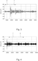
- Fig. 3 shows a measurement signal received by the second ultrasonic transducer 3, comprising a useful signal 7 and an interference signal 8.
- the interference amplitude is determined from the interference signal 8, which is present at the second ultrasonic transducer 3 before the useful signal 7.
- the interference amplitude can be determined from the interference signal 8, which hits the ultrasonic transducer 3 after the useful signal 7.
- Fig. 4 shows a further measurement signal received by the second ultrasonic transducer 3, comprising a useful signal 7 and an interference signal 8.
- the interference amplitude is determined from the interference signal 8, which is present at the second ultrasonic transducer 3 after the useful signal 7.
- Fig. 5 shows a first exemplary embodiment of a method 9 according to the invention for operating an ultrasonic flow measuring device 1.
- the ultrasonic flow measuring device 1 is as in Fig. 1 shown trained.
- the first ultrasonic transducer 2 sends out a measurement signal in the direction of the second ultrasonic transducer 3.
- a first part of the measurement signal propagates as an interference signal 8 along and/or within the measuring tube wall 5, a second part of the measurement signal propagates through the medium as a useful signal 7.
- the second ultrasonic transducer 3 receives the interference signal 8 and the useful signal 7 and forwards the interference signal 8 and the useful signal 7 to the control and evaluation unit 6.
- control and evaluation unit determines the interference amplitude of the interference signal 8 and the useful amplitude of the useful signal 7.
- the interference amplitude and the useful amplitude can be determined according to all of the variants explained above.
- the control and evaluation unit 6 determines 13 the amplitude ratio of the useful amplitude and the interference amplitude.
- a message in particular in the form of a message to the user, is issued 14, so that the user is informed that the measurement accuracy is currently reduced.
- the method 9 shown for operating an ultrasonic flow measuring device 1 has an improvement in that the determination of the measurement deviation caused by an interference signal can be monitored online, so that immediate or early measures can be taken to correct the increased measurement deviation.
Landscapes
- Physics & Mathematics (AREA)
- Fluid Mechanics (AREA)
- General Physics & Mathematics (AREA)
- Electromagnetism (AREA)
- Measuring Volume Flow (AREA)
Applications Claiming Priority (1)
| Application Number | Priority Date | Filing Date | Title |
|---|---|---|---|
| DE102022122181.4A DE102022122181A1 (de) | 2022-09-01 | 2022-09-01 | Verfahren zum Betreiben eines Ultraschalldurchflussmessgeräts und Ultraschalldurchflussmessgerät |
Publications (2)
| Publication Number | Publication Date |
|---|---|
| EP4332517A1 true EP4332517A1 (fr) | 2024-03-06 |
| EP4332517B1 EP4332517B1 (fr) | 2026-03-18 |
Family
ID=87863249
Family Applications (1)
| Application Number | Title | Priority Date | Filing Date |
|---|---|---|---|
| EP23193860.6A Active EP4332517B1 (fr) | 2022-09-01 | 2023-08-29 | Procédé de fonctionnement d'un débitmètre à ultrasons et débitmètre à ultrasons |
Country Status (4)
| Country | Link |
|---|---|
| US (1) | US20240077345A1 (fr) |
| EP (1) | EP4332517B1 (fr) |
| CN (1) | CN117629325A (fr) |
| DE (1) | DE102022122181A1 (fr) |
Cited By (1)
| Publication number | Priority date | Publication date | Assignee | Title |
|---|---|---|---|---|
| US20220074773A1 (en) * | 2020-09-10 | 2022-03-10 | Krohne Ag | Method for Operating an Ultrasonic Flowmeter and Ultrasonic Flowmeter |
Citations (4)
| Publication number | Priority date | Publication date | Assignee | Title |
|---|---|---|---|---|
| US20030172743A1 (en) * | 1999-04-01 | 2003-09-18 | Xiaolei Ao | Clamp-on flow meter system |
| US20040123666A1 (en) * | 2002-12-31 | 2004-07-01 | Ao Xiaolei S. | Ultrasonic damping material |
| US7096135B2 (en) * | 2004-03-12 | 2006-08-22 | Panametrics, Inc. | Method and system for calculating the transit time of an ultrasonic pulse |
| EP3521773A1 (fr) * | 2018-02-06 | 2019-08-07 | SICK Engineering GmbH | Dispositif ultrasonore de mesure d'écoulement et procédé de détermination d'une vitesse d'écoulement |
Family Cites Families (6)
| Publication number | Priority date | Publication date | Assignee | Title |
|---|---|---|---|---|
| DE19626865A1 (de) * | 1996-07-04 | 1998-01-08 | Suedrohrbau Gmbh & Co | Verfahren zur Messung der Laufzeiten von Schallsignalen in einem Fluid sowie Schaltungsanordnung zur Messung der Laufzeiten von Schallsignalen |
| NL1008827C1 (nl) * | 1998-04-07 | 1999-10-08 | Nico Roosnek | Werkwijze en inrichting voor het meten van fysische parameters. |
| DE102005033865B4 (de) * | 2005-07-20 | 2015-02-05 | Robert Bosch Gmbh | Verfahren und Vorrichtung zur Auswertung eines mit einem Rauschsignal behafteten Nutzsignals |
| US7673525B2 (en) * | 2007-01-09 | 2010-03-09 | Schlumberger Technology Corporation | Sensor system for pipe and flow condition monitoring of a pipeline configured for flowing hydrocarbon mixtures |
| DE102012112516A1 (de) * | 2012-12-18 | 2014-06-18 | Endress + Hauser Flowtec Ag | Verfahren zur Verifizierung der Zuverlässigkeit von ermittelten Messdaten einer Ultraschall-Durchflussmessung nach der Laufzeitdifferenz-Methode und Ultraschalldurchflussmessgerät |
| DK3317658T3 (da) * | 2015-07-03 | 2020-11-30 | Kamstrup As | Turbiditetssensor baseret på ultralydsmålinger |
-
2022
- 2022-09-01 DE DE102022122181.4A patent/DE102022122181A1/de active Pending
-
2023
- 2023-08-29 EP EP23193860.6A patent/EP4332517B1/fr active Active
- 2023-08-30 US US18/458,463 patent/US20240077345A1/en active Pending
- 2023-09-01 CN CN202311125565.8A patent/CN117629325A/zh active Pending
Patent Citations (4)
| Publication number | Priority date | Publication date | Assignee | Title |
|---|---|---|---|---|
| US20030172743A1 (en) * | 1999-04-01 | 2003-09-18 | Xiaolei Ao | Clamp-on flow meter system |
| US20040123666A1 (en) * | 2002-12-31 | 2004-07-01 | Ao Xiaolei S. | Ultrasonic damping material |
| US7096135B2 (en) * | 2004-03-12 | 2006-08-22 | Panametrics, Inc. | Method and system for calculating the transit time of an ultrasonic pulse |
| EP3521773A1 (fr) * | 2018-02-06 | 2019-08-07 | SICK Engineering GmbH | Dispositif ultrasonore de mesure d'écoulement et procédé de détermination d'une vitesse d'écoulement |
Cited By (2)
| Publication number | Priority date | Publication date | Assignee | Title |
|---|---|---|---|---|
| US20220074773A1 (en) * | 2020-09-10 | 2022-03-10 | Krohne Ag | Method for Operating an Ultrasonic Flowmeter and Ultrasonic Flowmeter |
| US12140461B2 (en) * | 2020-09-10 | 2024-11-12 | Krohne Ag | Method for operating an ultrasonic flowmeter and ultrasonic flowmeter |
Also Published As
| Publication number | Publication date |
|---|---|
| CN117629325A (zh) | 2024-03-01 |
| DE102022122181A1 (de) | 2024-03-07 |
| EP4332517B1 (fr) | 2026-03-18 |
| US20240077345A1 (en) | 2024-03-07 |
Similar Documents
| Publication | Publication Date | Title |
|---|---|---|
| DE2321583C2 (de) | Verfahren und Vorrichtung zur wiederholten und vergleichenden Inspektion von Volumenelementen einer Wandung | |
| EP2351996B1 (fr) | Procédé d'établissement d'une grandeur de référence pour la correction de valeurs de mesure d'un appareil de mesure du débit massique de Coriolis | |
| EP0059745A1 (fr) | Procede et dispositif de localisation et d'analyse d'emissions sonores. | |
| EP4367484B1 (fr) | Procédé d'étalonnage pour système de mesure de débit, système de mesure de débit et produit programme d'ordinateur | |
| EP4332517B1 (fr) | Procédé de fonctionnement d'un débitmètre à ultrasons et débitmètre à ultrasons | |
| DE202011005427U1 (de) | Vorrichtung zum Messen der Laufzeit eines Ultraschallsignals in einer strömenden Flüssigkeit | |
| EP3282233B1 (fr) | Procédé de fonctionnement d'un appareil de mesure de niveau de remplissage et appareil de mesure de niveau de remplissage | |
| EP3894799B1 (fr) | Agencement de transducteurs ultrasonores d'un appareil de mesure de debit a ultrasons a pinces, et appareil de mesure de debit a ultrasons a pinces et procede de mise en marche de l'appareil de mesure de debit a ultrasons a pinces | |
| EP3492878A1 (fr) | Procédé de détermination du temps de transit d'un signal ultrasonore dans un milieu fluide ainsi que débitmètre ultrasonore | |
| DE3136150A1 (de) | Verfahren und vorrichtung zur kontinuierlichen entgratungskonturmessung mittels ultraschall | |
| WO2014095246A1 (fr) | Appareil de mesure d'écoulements turbulents et procédé de mesure de la qualité de ses conditions de fonctionnement et de montage | |
| AT520557B1 (de) | Verfahren zur Ermittlung eines korrigierten Werts für die viskositätsabhängige Schallgeschwindigkeit in einem zu untersuchenden Fluid | |
| DE2317793A1 (de) | Verfahren und vorrichtung zum orten einer quelle impulsartiger signale | |
| EP1202031A1 (fr) | Procédé et appareil pour le contrôle de processus avec un capteur par induction magnétique | |
| EP3967989B1 (fr) | Procédé de fonctionnement d'un débitmètre à ultrasons et débitmètre à ultrasons | |
| DE2527286B2 (de) | Anordnung zur messung des luftmengenflusses durch eine leitung | |
| DE102024131387B3 (de) | Verfahren zum Betreiben eines Ultraschalldurchflussmessgeräts und Ultraschalldurchflussmessgerät | |
| DE3017900C2 (de) | Verfahren zur genauen automatischen Einstellung des Fehlererwartungsbereiches von Ultraschall-Rohr-Prüfanlagen zur zerstörungsfreien Werkstoffprüfung nach dem Impuls-Echo-Verfahren | |
| EP4033214A1 (fr) | Procédé d'étalonnage d'une unité de mesure de température basée sur la mesure ultrasonique, procédé de mesure de la température d'un milieu, unité de mesure de température et débitmètre à ultrasons | |
| EP3596455A1 (fr) | Dispositif et procédé de contrôle par ultrasons | |
| EP4553461B1 (fr) | Procédé de fonctionnement d'un appareil de mesure de niveau de remplissage du type tdr et appareil de mesure de niveau de remplissage du type tdr | |
| DE19520889A1 (de) | Verfahren und Meßgerät zur Erfassung der Einschubtiefe in einer Rohrverbindung | |
| EP0407676A1 (fr) | Procédé de mesure de différence de temps d'un ensemble d'ondes ultrasonores et dispositif de mesure pour sa mise en oeuvre | |
| DE3622902C2 (fr) | ||
| DE102006004582A1 (de) | Verfahren zur Diagnose einer Verstopfung einer Impulsleitung bei einem Druckmessumformer und Druckmessumformer |
Legal Events
| Date | Code | Title | Description |
|---|---|---|---|
| PUAI | Public reference made under article 153(3) epc to a published international application that has entered the european phase |
Free format text: ORIGINAL CODE: 0009012 |
|
| STAA | Information on the status of an ep patent application or granted ep patent |
Free format text: STATUS: THE APPLICATION HAS BEEN PUBLISHED |
|
| AK | Designated contracting states |
Kind code of ref document: A1 Designated state(s): AL AT BE BG CH CY CZ DE DK EE ES FI FR GB GR HR HU IE IS IT LI LT LU LV MC ME MK MT NL NO PL PT RO RS SE SI SK SM TR |
|
| STAA | Information on the status of an ep patent application or granted ep patent |
Free format text: STATUS: REQUEST FOR EXAMINATION WAS MADE |
|
| 17P | Request for examination filed |
Effective date: 20240906 |
|
| RBV | Designated contracting states (corrected) |
Designated state(s): AL AT BE BG CH CY CZ DE DK EE ES FI FR GB GR HR HU IE IS IT LI LT LU LV MC ME MK MT NL NO PL PT RO RS SE SI SK SM TR |
|
| STAA | Information on the status of an ep patent application or granted ep patent |
Free format text: STATUS: EXAMINATION IS IN PROGRESS |
|
| 17Q | First examination report despatched |
Effective date: 20250716 |
|
| GRAP | Despatch of communication of intention to grant a patent |
Free format text: ORIGINAL CODE: EPIDOSNIGR1 |
|
| STAA | Information on the status of an ep patent application or granted ep patent |
Free format text: STATUS: GRANT OF PATENT IS INTENDED |
|
| INTG | Intention to grant announced |
Effective date: 20251128 |
|
| GRAS | Grant fee paid |
Free format text: ORIGINAL CODE: EPIDOSNIGR3 |
|
| GRAA | (expected) grant |
Free format text: ORIGINAL CODE: 0009210 |
|
| STAA | Information on the status of an ep patent application or granted ep patent |
Free format text: STATUS: THE PATENT HAS BEEN GRANTED |
|
| AK | Designated contracting states |
Kind code of ref document: B1 Designated state(s): AL AT BE BG CH CY CZ DE DK EE ES FI FR GB GR HR HU IE IS IT LI LT LU LV MC ME MK MT NL NO PL PT RO RS SE SI SK SM TR |
|
| REG | Reference to a national code |
Ref country code: CH Ref legal event code: F10 Free format text: ST27 STATUS EVENT CODE: U-0-0-F10-F00 (AS PROVIDED BY THE NATIONAL OFFICE) Effective date: 20260318 Ref country code: GB Ref legal event code: FG4D Free format text: NOT ENGLISH |
|
| REG | Reference to a national code |
Ref country code: DE Ref legal event code: R096 Ref document number: 502023003405 Country of ref document: DE |
|
| REG | Reference to a national code |
Ref country code: IE Ref legal event code: FG4D Free format text: LANGUAGE OF EP DOCUMENT: GERMAN |
|
| P01 | Opt-out of the competence of the unified patent court (upc) registered |
Free format text: CASE NUMBER: UPC_APP_0010164_4332517/2026 Effective date: 20260317 |