EP4333010A1 - Procédé de mise sous tension d'un relais pour provoquer un courant d'appel minimal - Google Patents
Procédé de mise sous tension d'un relais pour provoquer un courant d'appel minimal Download PDFInfo
- Publication number
- EP4333010A1 EP4333010A1 EP23170049.3A EP23170049A EP4333010A1 EP 4333010 A1 EP4333010 A1 EP 4333010A1 EP 23170049 A EP23170049 A EP 23170049A EP 4333010 A1 EP4333010 A1 EP 4333010A1
- Authority
- EP
- European Patent Office
- Prior art keywords
- time
- inrush current
- relay
- switch
- switching
- Prior art date
- Legal status (The legal status is an assumption and is not a legal conclusion. Google has not performed a legal analysis and makes no representation as to the accuracy of the status listed.)
- Pending
Links
Images


Classifications
-
- H—ELECTRICITY
- H01—ELECTRIC ELEMENTS
- H01H—ELECTRIC SWITCHES; RELAYS; SELECTORS; EMERGENCY PROTECTIVE DEVICES
- H01H9/00—Details of switching devices, not covered by groups H01H1/00 - H01H7/00
- H01H9/54—Circuit arrangements not adapted to a particular application of the switching device and for which no provision exists elsewhere
- H01H9/56—Circuit arrangements not adapted to a particular application of the switching device and for which no provision exists elsewhere for ensuring operation of the switch at a predetermined point in the AC cycle
- H01H9/563—Circuit arrangements not adapted to a particular application of the switching device and for which no provision exists elsewhere for ensuring operation of the switch at a predetermined point in the AC cycle for multipolar switches, e.g. different timing for different phases, selecting phase with first zero-crossing
-
- H—ELECTRICITY
- H01—ELECTRIC ELEMENTS
- H01H—ELECTRIC SWITCHES; RELAYS; SELECTORS; EMERGENCY PROTECTIVE DEVICES
- H01H47/00—Circuit arrangements not adapted to a particular application of the relay and designed to obtain desired operating characteristics or to provide energising current
- H01H47/02—Circuit arrangements not adapted to a particular application of the relay and designed to obtain desired operating characteristics or to provide energising current for modifying the operation of the relay
- H01H47/18—Circuit arrangements not adapted to a particular application of the relay and designed to obtain desired operating characteristics or to provide energising current for modifying the operation of the relay for introducing delay in the operation of the relay
-
- H—ELECTRICITY
- H01—ELECTRIC ELEMENTS
- H01H—ELECTRIC SWITCHES; RELAYS; SELECTORS; EMERGENCY PROTECTIVE DEVICES
- H01H9/00—Details of switching devices, not covered by groups H01H1/00 - H01H7/00
- H01H9/54—Circuit arrangements not adapted to a particular application of the switching device and for which no provision exists elsewhere
- H01H9/56—Circuit arrangements not adapted to a particular application of the switching device and for which no provision exists elsewhere for ensuring operation of the switch at a predetermined point in the AC cycle
- H01H2009/566—Circuit arrangements not adapted to a particular application of the switching device and for which no provision exists elsewhere for ensuring operation of the switch at a predetermined point in the AC cycle with self learning, e.g. measured delay is used in later actuations
Definitions
- the invention relates to a method for switching on a relay switching an AC-powered load to effect a minimum inrush current through the relay.
- This switching inertia is system-related and is due to the necessary build-up of the magnetic field due to the current supply to the relay coil and the path to be covered by the movable switching contacts.
- the movable relay contacts work against the force of a return spring, which brakes the desired movement of the movable switching contacts and thus slows it down.
- the switching inertia of such a relay depends on its design and can be between 3 - 10 ms, for example.
- the relay is then controlled by its control electronics in such a way that the switch-on time is before the next expected zero crossing of the alternating voltage by the duration of the switching inertia.
- This value is basically a size specified by the manufacturer.
- the switching inertia can also be determined automatically by the relay circuit, as can a change in the switching inertia as a result of, for example, aging of the relay.
- the invention is based on the object of proposing a method for switching on a relay to effect a minimum inrush current, with which the installation space requirement is minimized, ghosting or flashing of LED lamps switched with a relay is effectively avoided and Even the smallest signals can be switched reliably.
- This method of switching on a relay that switches an AC-powered load requires monitoring the network voltage to determine a fixed synchronization point at the network frequency.
- the inrush currents - 20 - 60 switch-on processes are usually sufficient for calibration - are detected using the magnetic field generated by the inrush current.
- the inrush current can be deduced using a suitable magnetic field sensor, in particular a conductor loop (corresponds to an antenna), and the voltage induced in the same.
- the intensity of the induced voltage is proportional to the inrush current.
- the inrush current is recorded for different time intervals between the time of its switch-on control and the time of the synchronization point.
- inrush current curve results for different time intervals between the time of its switch-on control and the time of the (held) synchronization point.
- Such a curve will have a minimum inrush current that corresponds to a specific (switch-on) time.
- the relay is activated as a result of the method according to the invention, so that the closing of the relay contacts is only accompanied by a minimal inrush current.
- the time of the minimum inrush current is identified again in the vicinity of the time of the minimum inrush current identified with the time period. After a first rough scan run to find the time of the minimum inrush current, a scan run is carried out again, with a reduced time duration. Due to the resulting higher time resolution, the time of the minimum inrush current can be determined particularly precisely and with relatively little computing and time effort.
- the method according to the invention is used for several channels, with the network synchronization only taking place at any one phase.
- the network synchronization For an actuator that has a relay and, for example, has three channels that switch different phases, it is sufficient to synchronize at any phase.
- the optimal switching time for switching at the current minimum can then be determined for each phase relative to this one synchronization point, since all phases are always 120° apart from each other.
- the time corresponding to the minimum inrush current is determined several times and an average value is formed from a predefined number of measurements. This represents a further opportunity to improve the precision of the procedure.
- the monitoring of the current curve in the current monitoring device is carried out using a conductor loop as a magnetic field sensor.
- the conductor loop detects the magnetic field that is generated by the switch-on process.
- control and evaluation is carried out by a microcontroller, in particular by a microcontroller for an actuator having several channels.
- the method according to the invention is carried out in a self-learning manner, in particular when a minimum inrush current occurs that increases over time. This allows aging effects that shift the time corresponding to the minimum inrush current to be automatically taken into account.
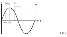
- FIGS. 1 to 3 schematic diagrams are shown which visualize the step-by-step determination of the inrush currents I (corresponding to a specific switch-on time, which is spaced by a specific time interval with respect to the synchronization point).
- a fixed synchronization point t sync at the network frequency is required.
- the mains voltage is monitored, which is shown as U in the figures.
- the inrush current I is detected over at least one half-wave through the relay contacts with the help of a magnetic field sensor, which detects the magnetic field that is generated by the switch-on process.
- the time interval t delta varies, a large number of inrush currents are obtained (note: in the Figures 1 to 3 only the inrush current I corresponding to the respective time is shown), whereupon the time t ein2 (see Figure 2 ) corresponding to the minimum inrush current I min is determined from the large number of inrush currents over the half wave.
- the relay can be activated at time t on2 , so that closing the relay contacts causes a minimum inrush current I min .
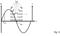
- FIG 4 A schematic diagram is shown in which the inrush currents determined from the figures Fig. 1 and Fig. 3 are marked. In this respect shows Figure 4 an inrush current curve.
- the time of the minimum inrush current t min in the vicinity of the time of the minimum inrush current t min identified with the time period t delta is identified again with a reduced time period t delta .
Landscapes
- Engineering & Computer Science (AREA)
- Power Engineering (AREA)
- Keying Circuit Devices (AREA)
Applications Claiming Priority (1)
| Application Number | Priority Date | Filing Date | Title |
|---|---|---|---|
| DE102022121898.8A DE102022121898A1 (de) | 2022-08-30 | 2022-08-30 | Verfahren zum Einschalten eines Relais zum Bewirken eines minimalen Einschaltstroms |
Publications (1)
| Publication Number | Publication Date |
|---|---|
| EP4333010A1 true EP4333010A1 (fr) | 2024-03-06 |
Family
ID=86226950
Family Applications (1)
| Application Number | Title | Priority Date | Filing Date |
|---|---|---|---|
| EP23170049.3A Pending EP4333010A1 (fr) | 2022-08-30 | 2023-04-26 | Procédé de mise sous tension d'un relais pour provoquer un courant d'appel minimal |
Country Status (2)
| Country | Link |
|---|---|
| EP (1) | EP4333010A1 (fr) |
| DE (1) | DE102022121898A1 (fr) |
Citations (7)
| Publication number | Priority date | Publication date | Assignee | Title |
|---|---|---|---|---|
| DE29701352U1 (de) | 1997-01-29 | 1997-04-17 | Domotec Ag, Aarburg | Schaltungsanordnung zum Ein- und Ausschalten eines durch eine Last fließenden elektrischen Wechselstroms |
| DE19808229A1 (de) * | 1998-02-27 | 1999-09-02 | Pks Systemtechnik | Verfahren zum wiederholten Ansteuern einer einen Wechselstromkreis schaltenden Schalteinrichtung |
| EP0997921A1 (fr) * | 1998-10-28 | 2000-05-03 | ABBPATENT GmbH | Procédé et dispositif de commande pour un relais électromécanique |
| DE10029789C1 (de) * | 2000-06-16 | 2001-10-11 | Siemens Ag | Verfahren zum Betrieb eines elektromagnetischen Schaltgeräts und elektromagnetisches Schaltgerät |
| US20120206851A1 (en) * | 2009-12-14 | 2012-08-16 | Patrick Weber | Method for controlling the opening or closing of an electric circuit in an electric meter |
| EP3266031B1 (fr) * | 2015-03-06 | 2020-02-19 | Wöhner GmbH & Co. KG Elektrotechnische Systeme | Dispositif de commutation permettant de faire fonctionner au moins une charge |
| EP3605579B1 (fr) | 2018-07-30 | 2020-09-09 | Insta GmbH | Procédé de commutation à point zéro d'un relais |
Family Cites Families (1)
| Publication number | Priority date | Publication date | Assignee | Title |
|---|---|---|---|---|
| DE102020215410A1 (de) * | 2020-12-07 | 2022-06-09 | Robert Bosch Gesellschaft mit beschränkter Haftung | Stromstärkemessung |
-
2022
- 2022-08-30 DE DE102022121898.8A patent/DE102022121898A1/de active Pending
-
2023
- 2023-04-26 EP EP23170049.3A patent/EP4333010A1/fr active Pending
Patent Citations (7)
| Publication number | Priority date | Publication date | Assignee | Title |
|---|---|---|---|---|
| DE29701352U1 (de) | 1997-01-29 | 1997-04-17 | Domotec Ag, Aarburg | Schaltungsanordnung zum Ein- und Ausschalten eines durch eine Last fließenden elektrischen Wechselstroms |
| DE19808229A1 (de) * | 1998-02-27 | 1999-09-02 | Pks Systemtechnik | Verfahren zum wiederholten Ansteuern einer einen Wechselstromkreis schaltenden Schalteinrichtung |
| EP0997921A1 (fr) * | 1998-10-28 | 2000-05-03 | ABBPATENT GmbH | Procédé et dispositif de commande pour un relais électromécanique |
| DE10029789C1 (de) * | 2000-06-16 | 2001-10-11 | Siemens Ag | Verfahren zum Betrieb eines elektromagnetischen Schaltgeräts und elektromagnetisches Schaltgerät |
| US20120206851A1 (en) * | 2009-12-14 | 2012-08-16 | Patrick Weber | Method for controlling the opening or closing of an electric circuit in an electric meter |
| EP3266031B1 (fr) * | 2015-03-06 | 2020-02-19 | Wöhner GmbH & Co. KG Elektrotechnische Systeme | Dispositif de commutation permettant de faire fonctionner au moins une charge |
| EP3605579B1 (fr) | 2018-07-30 | 2020-09-09 | Insta GmbH | Procédé de commutation à point zéro d'un relais |
Also Published As
| Publication number | Publication date |
|---|---|
| DE102022121898A1 (de) | 2024-02-29 |
Similar Documents
| Publication | Publication Date | Title |
|---|---|---|
| DE3028395C2 (fr) | ||
| EP3605579B1 (fr) | Procédé de commutation à point zéro d'un relais | |
| EP3000118B1 (fr) | Dispositif de commutation à courant continu | |
| DE2457304A1 (de) | Verfahren und vorrichtung zur ueberwachung eines bearbeitungsvorgangs mittels funkenerosion | |
| EP0997921B1 (fr) | Procédé et dispositif de commande pour un relais électromécanique | |
| EP0030320A1 (fr) | Procédé d'enregistrement de décharges dans un filtre électrostatique | |
| DE19751828B4 (de) | Verfahren und Vorrichtung zur Erkennung und Steuerung von elektronischen Schaltnetzteilen oder konventionellen Transformatoren, jeweils mit oder ohne ohmscher Last, insbesondere von Beleuchtungseinrichtungen | |
| EP0575715B1 (fr) | Procédé et dispositif pour éviter des courants d'entrée | |
| EP0534250A2 (fr) | Procédé et dispositif pour protéger un circuit courant alternatif | |
| DE102022121898A1 (de) | Verfahren zum Einschalten eines Relais zum Bewirken eines minimalen Einschaltstroms | |
| DE2202010C2 (de) | Verfahren und Einrichtung zur Steuerung der elektrischen Leistung in einem Drehspannungsnetz mit N Phasenleitern | |
| EP3977496B1 (fr) | Procédé de prédiction de défaillance d'un relais élémentaire | |
| EP4500566B1 (fr) | Procédé d'actionnement d'un changeur de prise en charge et dispositif de changeur de prise en charge | |
| WO2002033716A1 (fr) | Procede et dispositif pour reduire l'usure des contacts d'un appareil de coupure | |
| EP3306329B1 (fr) | Procédé de surveillance centrale de changements d'état d'une pluralité de composants pour installations haute tension à partir de 1 kv. | |
| DE2735736B2 (de) | Wechselstromschalteinrichtung | |
| EP0313542B1 (fr) | Dispositif d'enclenchement contrôlé d'éléments inductifs dans le réseau haute tension | |
| DE202022107140U1 (de) | Relaisschaltung | |
| DE19606503C2 (de) | Verfahren und Schaltungsanordnungen zum Erzielen phasensynchronen Schaltens in der Nähe der Spannungsnulldurchgänge von in Wechselspannungsanlagen liegenden Kontakten | |
| WO2018059649A1 (fr) | Circuit à relais | |
| DE2936549C2 (fr) | ||
| EP0019904A1 (fr) | Relais de surcharge de protection | |
| DE102016106474B3 (de) | Nebenschlussmodul sowie Verfahren zum Bereitstellen des notwendigen Betriebsstromes für einen Dimmer | |
| DE766170C (de) | Anordnung zur Anzeige bzw. zum Ausgleich ungleichmaessiger Belastung von ueber magnetisch wirkende Stromteiler parallel arbeitenden Stromrichtern | |
| AT340477B (de) | Schaltung fur den betrieb einer prufschaltung bei lichtsignalen |
Legal Events
| Date | Code | Title | Description |
|---|---|---|---|
| PUAI | Public reference made under article 153(3) epc to a published international application that has entered the european phase |
Free format text: ORIGINAL CODE: 0009012 |
|
| STAA | Information on the status of an ep patent application or granted ep patent |
Free format text: STATUS: THE APPLICATION HAS BEEN PUBLISHED |
|
| AK | Designated contracting states |
Kind code of ref document: A1 Designated state(s): AL AT BE BG CH CY CZ DE DK EE ES FI FR GB GR HR HU IE IS IT LI LT LU LV MC ME MK MT NL NO PL PT RO RS SE SI SK SM TR |
|
| STAA | Information on the status of an ep patent application or granted ep patent |
Free format text: STATUS: REQUEST FOR EXAMINATION WAS MADE |
|
| 17P | Request for examination filed |
Effective date: 20240312 |
|
| RBV | Designated contracting states (corrected) |
Designated state(s): AL AT BE BG CH CY CZ DE DK EE ES FI FR GB GR HR HU IE IS IT LI LT LU LV MC ME MK MT NL NO PL PT RO RS SE SI SK SM TR |
|
| STAA | Information on the status of an ep patent application or granted ep patent |
Free format text: STATUS: EXAMINATION IS IN PROGRESS |
|
| 17Q | First examination report despatched |
Effective date: 20250214 |