EP3605579B1 - Procédé de commutation à point zéro d'un relais - Google Patents
Procédé de commutation à point zéro d'un relais Download PDFInfo
- Publication number
- EP3605579B1 EP3605579B1 EP19178316.6A EP19178316A EP3605579B1 EP 3605579 B1 EP3605579 B1 EP 3605579B1 EP 19178316 A EP19178316 A EP 19178316A EP 3605579 B1 EP3605579 B1 EP 3605579B1
- Authority
- EP
- European Patent Office
- Prior art keywords
- relay
- voltage
- switching
- inertia
- switch
- Prior art date
- Legal status (The legal status is an assumption and is not a legal conclusion. Google has not performed a legal analysis and makes no representation as to the accuracy of the status listed.)
- Active
Links
Images
Classifications
-
- H—ELECTRICITY
- H01—ELECTRIC ELEMENTS
- H01H—ELECTRIC SWITCHES; RELAYS; SELECTORS; EMERGENCY PROTECTIVE DEVICES
- H01H47/00—Circuit arrangements not adapted to a particular application of the relay and designed to obtain desired operating characteristics or to provide energising current
- H01H47/02—Circuit arrangements not adapted to a particular application of the relay and designed to obtain desired operating characteristics or to provide energising current for modifying the operation of the relay
- H01H47/20—Circuit arrangements not adapted to a particular application of the relay and designed to obtain desired operating characteristics or to provide energising current for modifying the operation of the relay for producing frequency-selective operation of the relay
-
- H—ELECTRICITY
- H01—ELECTRIC ELEMENTS
- H01H—ELECTRIC SWITCHES; RELAYS; SELECTORS; EMERGENCY PROTECTIVE DEVICES
- H01H9/00—Details of switching devices, not covered by groups H01H1/00 - H01H7/00
- H01H9/54—Circuit arrangements not adapted to a particular application of the switching device and for which no provision exists elsewhere
- H01H9/56—Circuit arrangements not adapted to a particular application of the switching device and for which no provision exists elsewhere for ensuring operation of the switch at a predetermined point in the AC cycle
-
- H—ELECTRICITY
- H01—ELECTRIC ELEMENTS
- H01H—ELECTRIC SWITCHES; RELAYS; SELECTORS; EMERGENCY PROTECTIVE DEVICES
- H01H9/00—Details of switching devices, not covered by groups H01H1/00 - H01H7/00
- H01H9/54—Circuit arrangements not adapted to a particular application of the switching device and for which no provision exists elsewhere
- H01H9/56—Circuit arrangements not adapted to a particular application of the switching device and for which no provision exists elsewhere for ensuring operation of the switch at a predetermined point in the AC cycle
- H01H2009/566—Circuit arrangements not adapted to a particular application of the switching device and for which no provision exists elsewhere for ensuring operation of the switch at a predetermined point in the AC cycle with self learning, e.g. measured delay is used in later actuations
-
- H—ELECTRICITY
- H01—ELECTRIC ELEMENTS
- H01H—ELECTRIC SWITCHES; RELAYS; SELECTORS; EMERGENCY PROTECTIVE DEVICES
- H01H47/00—Circuit arrangements not adapted to a particular application of the relay and designed to obtain desired operating characteristics or to provide energising current
- H01H2047/009—Circuit arrangements not adapted to a particular application of the relay and designed to obtain desired operating characteristics or to provide energising current with self learning features, e.g. measuring the attracting current for a relay and memorising it
Definitions
- the invention also relates to a relay circuit, in particular for carrying out the aforementioned method, with a relay provided for switching an AC voltage-fed load and with control electronics for driving the relay.
- Relay circuits and methods for switching a relay to zero are previously known.
- the previously known method for zero point switching of an AC-powered load switching relay one would like to extend the service life of the relay with regard to the number of its switching cycles by switching the relay contacts in or in the area of the zero crossing of the AC voltage. This prevents the generation of switching sparks.
- Switching sparks are arcs that form between the switching contacts when they are not closed and as long as their distance is not sufficiently large. Such arcs remove material from the switch contacts. The higher the voltage or the current at the time of switching, the more intense the formation of such a switching arc. For this reason, methods and relay circuits have been developed with which such a relay is switched in the area of the zero crossing of the alternating voltage.
- Such a relay circuit is previously known, for example DE 297 01 352 U1 .
- the switching inertia of the relay is the period of time that the relay needs until the relay contacts are actually closed after receiving a switch-on control signal.
- This switching inertia is due to the system and is due to the necessary build-up of the magnetic field due to the energization of the relay coil and the distance to be covered by the movable switching contacts.
- the movable relay contacts work against the force of a return spring, which brakes and thus slows down the desired movement of the movable switching contacts.
- the switching inertia of such a relay is therefore dependent on its design and can be between 3 and 10 ms, for example.
- the relay With the determined switching inertia, the relay is then activated by its control electronics in such a way that the switch-on time is by the duration of the switching inertia before the next expected zero crossing of the alternating voltage.
- This value is basically a value specified by the manufacturer.
- the switching inertia can also be determined automatically by the relay circuit, as can a change in the switching inertia as a result of, for example, aging of the relay. For this purpose, it is proposed in the prior art that the occurrence of a switching spark be determined optically and, when such a switching spark is detected, the next triggering of the relay is triggered with a switching inertia shifted by a fraction of a period. Alternatively, the course of the current can be observed.
- EP 0 997 921 A1 Another method for zero point switching of a relay and a corresponding relay circuit are out EP 0 997 921 A1 known. With this method and this relay circuit, too, the current flow is over the load is used to determine the switching inertia. Such is also disclosed in DE 10 2005 051 762 A1 and EP 2 107 585 A2 such as US 2017/0229269 A1 .
- a relay circuit in which the voltage across the relay contacts is measured to determine the closed state of the relay.
- the invention is based on the object of proposing a method mentioned at the beginning for zero point switching of an AC-fed load switching relay and a relay circuit with which not only the switching inertia of a relay is independent of the type of this switched load is possible, but which relay circuit is also simple and therefore inexpensive.
- Task of The invention is also to improve the determination of the time of the switching process.
- the method-related aspect of the above-mentioned object is achieved according to the invention in that the switching inertia is determined several times and a mean value is formed from a predefined number of switching inertia measurements, which represents the switching inertia to be taken into account when determining the time of triggering the relay.
- the aspect of the task related to the relay circuit is achieved by a generic relay circuit mentioned at the outset, in which the relay circuit has a voltage measuring device for detecting the voltage across the relay contacts.
- the switching inertia of the relay is determined from the voltage that can be detected via the relay contacts. If the relay contacts are open, a voltage can be measured between them. If the relay contacts are closed, no voltage can be detected. Since no voltage is measured across the relay contacts when the relay contacts are closed, this method can be used to effectively determine the switching inertia of the relay, regardless of the type of load switched by the relay. In addition, a voltage measurement is possible with much simpler means than a current measurement. While a voltage measurement is practically powerless, with a current measurement, the larger the current, the more power must be converted in the measuring device. As a result, the circuit structure of the relay circuit, when the voltage is detected via the switching contacts to determine the switching inertia of the relay, is less complex than a circuit that is required for a current measurement.
- the state of the relay contact is determined by continuously differentiating the voltage across the relay contacts, which is also referred to below as contact voltage. If a certain slope is reached, this defines the relay contact closed state or in the case of determining the switching inertia during the switch-off process, the relay contact open state. In this way, inaccuracies relating to the transition contact can be compensated in a particularly simple manner, especially during the switch-on process, for example by bouncing the contacts and the like. This improves the accuracy of the time measurement between the transmission of the control signal to the relay and the definition of the relay contact closed state.
- the relay switches an alternating voltage. If this voltage curve is used to differentiate, the result is that the switching state change takes place when the ascertained slope is zero. However, this can correspond to the lower extremum, the upper extremum or the closed switching contact.
- an absolute voltage range is also defined in this embodiment, in which the voltage must lie so that a change of state is registered. The state when the relay contact is closed is in this range, but not the upper or lower extremum. This avoids the assumption of a point in time as the measurement point in time at which there is actually only one extreme of the alternating voltage.
- the voltage curve of the voltage applied to the relay is monitored, specifically to determine the point in time of the next expected zero crossing of the applied AC voltage.
- the measured time span between the time of activation of the relay and the time of the closed or opened relay contacts, which defines the switching inertia is subtracted from the expected zero-crossing time at the time of activation for controlling the relay. Consequently, the relay is not only activated at the point in time of a zero crossing of the alternating voltage, but at an earlier point in time, which corresponds to the point in time of the expected zero crossing minus the switching inertia of the relay. In this way, the relay switches in a very narrow range around the zero crossing and thus at a point in time in the alternating voltage curve in which no or only a very low one Voltage is applied and thus the risk of switching sparks or switching arcs is effectively prevented.
- the switching inertia during the switch-off process is usually lower than that during the switch-on process, which is due to the fact that the switch-off is effected by the restoring force of one or more spring elements and, unlike the switch-on process, a magnetic field does not have to be built up first.
- the monitoring of the voltage curve of the voltage applied to the relay can, as this is provided in one embodiment, be carried out by a voltage divider connecting the phase to the neutral conductor.
- the hardware required for this is low.
- An embodiment is also entirely possible in which the control electronics themselves have zero crossing detection. This can of course also be used to monitor the voltage curve of the voltage applied to the relay.
- the switching inertia To minimize measurement inaccuracies when determining the switching inertia, it is averaged from a number of individual measurements.
- the averaged value represents the switching inertia to be taken into account when triggering the relay.
- These measurements can be carried out with several successive switching processes. It is also entirely possible that the measurements are not used by several consecutive switching operations, but instead every nth switching operation.
- the determined switching inertia can be low-pass filtered.
- the switching inertia can easily be determined during the switch-on process or also during the switch-off process for each switching process. It goes without saying that corresponding results can also be obtained if the Switching inertia determinations are not made for every switching process, but for every nth switching process. This measure automatically adapts a switching inertia of the relay that changes, for example, as a result of aging. No switching inertia needs to be specified by the manufacturer if the described method is carried out at least in a first operating phase of the relay.
- the switching inertia is already recorded with sufficient accuracy after a few switching operations to ensure the desired zero point switching in a narrow range around the zero crossing.
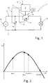
- a relay circuit 1 comprises a relay 2, which is controlled by control electronics 3 designed as a microcontroller in the exemplary embodiment shown.
- the control electronics 3 have a control input 4 to which a control signal is applied when the relay 2 is to be switched.
- the relay 2 is switched on for switching phase 5 of an alternating current circuit in the circuit.
- the relay 2 switches an AC-fed load, which is an LED light 6 in the illustrated embodiment.
- the neutral wire is in Figure 1 marked with the reference number 7.
- the phase 5 and the neutral conductor 7 are connected to an alternating current voltage source 8, which in the illustrated embodiment is the mains voltage.
- the relay 2 has a fixed relay contact 9 and a movable relay contact 10.
- the relay 2 is shown in its open position, in which the two relay contacts 9, 10 are spaced apart and the LED lamp 6 is not energized.
- a voltage measuring device 11 Connected to relay contacts 9, 10 is a voltage measuring device 11, the signal line 12 of which is connected to a first signal input of control electronics 3.
- the voltage measuring device 11 measures the voltage via the relay contacts 9, 10 in order to determine the respective switching inertia, i.e. the time between the receipt of a switch-on control signal at the control input 4 and the state that the relay contacts 9, 10 are closed, is determined.
- the switching inertia of the relay 2 when it is switched off is determined on the basis of the closed relay contacts 9, 10.
- the relay contacts 9, 10 are open, the AC voltage is measured by the voltage measuring device 11, in the present case the mains voltage.
- the relay contacts 9, 10 are closed, the LED light 6 is energized and no voltage can be detected at the voltage measuring device 11.
- the switching inertia of the relay 2 can be determined with the relay circuit 1 for every load and in particular also for inductive loads.
- An electronic memory 13 in which the results of the switching inertia measurements are stored, is connected to the control electronics 3.
- the memory 13 is organized in the manner of a ring or register memory, so that a certain number of switching inertia measurements can be stored therein.
- the relay circuit 1 also has a voltage monitoring device 14 which, in the exemplary embodiment shown, is designed as a voltage divider.
- the voltage monitoring device 14 is connected between the phase 5 and the neutral conductor 7 or connects the phase 5 to the neutral conductor 7.
- the voltage monitoring device 14 monitors the course of the mains voltage with regard to the zero crossings of the alternating voltage.
- the signal line 15 the voltage monitoring device 14 is connected to a second signal input of the control electronics 3.
- Relay 2 can be switched to zero with relay circuit 1. This means that the relay contacts 9, 10 have reached their closed state or a state reflecting this state during a switch-on process in the area of the zero crossing of an alternating voltage half-wave. When switching off, the relay contacts 9, 10 are opened in the area of the zero crossing.
- the switching inertia of the relay 2 during the switch-on process is determined in a first step. In the exemplary embodiment shown, that time is recorded via the control device 3 for this purpose, which is required so that the relay contacts 9, 10 are closed after a corresponding control signal has been applied to the control input 4. If a switch-on control signal is present at control input 4, time measurement begins. At the same time, the voltage across the relay contacts 9, 10 is measured by the voltage measuring device 11. In the exemplary embodiment shown, the voltage is differentiated continuously until it has reached a predefined slope. If the differentiation has reached a certain slope, the voltage has reached an expected or predefined state that reflects the closed state. The expected voltage state is selected so that the relay contacts 9, 10 are then closed. The expected voltage state is set to 0V in the illustrated embodiment. The time measurement is ended when the specified slope is reached by differentiating the contact voltage (voltage across the relay contacts 9, 10). This determined time period corresponds to the switching inertia of relay 2.
- the AC voltage is monitored via the voltage monitoring device 14, specifically with regard to the point in time of the expected zero crossings.
- the relay 2 is activated by the control electronics 3 at a point in time for switching on which corresponds to the point in time of the next expected zero crossing of the alternating voltage minus the previously determined switching inertia of the relay 2.
- this activation switch-on process is shown in FIG Figure 2 marked with t on2 and the closed state of relay 2 with t switch2 .
- the time t switch2 is immediately adjacent to the actual zero crossing of the alternating voltage half-wave shown.
- the switching inertia of the relay 2 is not constant within certain limits, also due to changing environmental conditions, such as temperature or the like. For this reason, several switching inertia measurements are carried out to determine the switching inertia during the switch-on process and are stored in the memory 13. The current mean value is formed from the same number of previous switching inertia measurements, which is then used for the next switch-on process to determine the switch-on time.
- the relay circuit 1 works adaptively with respect to a changing switching behavior, be it due to changing environmental conditions, due to aging or otherwise.
- a determination of the switching inertia during a switch-off process is carried out in a similar manner.
- the above-described improvement in the switch-on process already leads to a significant increase in the service life of the relay 2 or its relay contacts 9, 10.
- the tolerances in the switching inertia during the switch-off process are lower, which is also due to the fact that no magnetic field is built up when switched off must become.
- the variance of the switching inertia when switching off is typically significantly lower than when switching on. It is therefore not absolutely necessary to determine the switching inertia during the switch-off process in the manner described.
- switching off one can therefore fall back on a switching inertia, which is used as a constant variable in the process. Changes due to aging can be reflected by changing this constant variable.
Landscapes
- Engineering & Computer Science (AREA)
- Power Engineering (AREA)
- Relay Circuits (AREA)
- Testing Electric Properties And Detecting Electric Faults (AREA)
Claims (14)
- Procédé de mise à zéro d'un relais (2) commutant une charge alimentée en courant alternatif, le procédé comprenant les étapes suivantes:- Détermination de l'inertie de commutation du relais (2) pendant le processus de mise en marche et/ou pendant le processus de coupure en détectant la tension par les contacts du relais (9, 10) entre le moment (tein1) de son actionnement de mise en marche ou de coupure et le moment (tschalt1) de la fermeture ou de l'ouverture des contacts du relais (9, 10),- Surveillance de la courbe de tension de la tension à commuter par le relais (2) pour déterminer le moment du prochain passage à zéro prévu et- Commande du relais (2) pour fermer ou ouvrir les contacts du relais (9, 10) à un moment (tein2) qui correspond au moment du passage par zéro prévu moins l'inertie d'enclenchement ou de déclenchement du relais (2),caractérisé en ce que l'inertie de commutation est déterminée plusieurs fois et qu'une valeur moyenne est calculée à partir d'un nombre prédéfini de mesures d'inertie de commutation, qui représente l'inertie de commutation à prendre en compte pour déterminer le moment d'actionnement du relais.
- Procédé selon la revendication 1, caractérisé en ce que, pour déterminer l'inertie de commutation du relais (2), la tension est continuellement différenciée par les contacts du relais (9, 10) et l'atteinte d'une pente prédéfinie de la tension définit l'état fermé du contact du relais ou l'état ouvert du contact du relais.
- Procédé selon la revendication 1 ou 2, caractérisé en ce que l'opération de détermination de l'inertie de mise en marche et/ou de l'inertie d'arrêt est effectuée à chaque opération de mise en marche ou d'arrêt.
- Procédé selon la revendication 3, caractérisé en ce que les résultats de la détermination de la valeur moyenne de l'inertie de commutation sont filtrés par un filtre passe-bas.
- Procédé selon l'une des revendications 1 à 4, caractérisé en ce que le moment de la fermeture ou de l'ouverture des contacts de relais (9, 10) est déterminé avec le cours actuel de la demi-onde de tension alternative par rapport à son intervalle de temps à partir du passage par zéro suivant la commutation du contact de relais (9, 10).
- Procédé selon la revendication 5, caractérisé en ce que, si un temps de différence prédéterminé est dépassé, celui-ci est pris en compte par rapport au temps d'activation lors de la prochaine activation du relais (2) pour la même opération de commutation - ouverture ou fermeture - afin de rapprocher l'opération de commutation effective du contact du relais au passage par zéro.
- Procédé selon l'une des revendications 1 à 6, caractérisé en ce que la surveillance de la courbe de tension est effectuée au moyen d'un dispositif de surveillance de la tension (14) reliant la phase (5) au conducteur neutre (7).
- Procédé selon la revendication 7, caractérisé en ce que la surveillance de la courbe de tension dans le dispositif de surveillance de la tension (14) est effectuée au moyen d'un diviseur de tension.
- Procédé selon l'une des revendications 1 à 7, caractérisé en ce que seule l'inertie de commutation du relais (2) est déterminée pendant le processus d'enclenchement et l'inertie de commutation pendant le processus de déclenchement est spécifiée comme une variable constante.
- Circuit de relais pour la mise en oeuvre du procédé selon l'une des revendications 1 à 9, avec un relais (2) prévu pour la commutation d'une charge alimentée en courant alternatif et avec une électronique de commande (3) pour la commande du relais (2), caractérisé en ce que le circuit de relais (1) dispose d'un dispositif de mesure de la tension (11) pour détecter la tension par les contacts de relais (9, 10).
- Circuit de relais selon la revendication 10, caractérisé en ce que le circuit de relais (1) comprend un dispositif de surveillance de la tension (14), qui relie la phase (5) au conducteur neutre (7), pour surveiller la courbe de tension.
- Circuit de relais selon la revendication 11, caractérisé en ce que le dispositif de surveillance de la tension (14) comprend un diviseur de tension par lequel la courbe de tension est surveillée.
- Circuit de relais selon la revendication 12, caractérisé en ce que l'électronique de commande (3) comprend une unité de détection de passage par zéro pour détecter le passage par zéro de la tension alternative.
- Circuit de relais selon l'une des revendications 9 à 13, caractérisé en ce que le dispositif de mesure de la tension (11) est réalisé par un circuit diviseur de tension ou un circuit comparateur.
Applications Claiming Priority (1)
| Application Number | Priority Date | Filing Date | Title |
|---|---|---|---|
| DE102018118329.1A DE102018118329B3 (de) | 2018-07-30 | 2018-07-30 | Verfahren zum Nullpunktschalten eines Relais sowie Relaisschaltung |
Publications (2)
| Publication Number | Publication Date |
|---|---|
| EP3605579A1 EP3605579A1 (fr) | 2020-02-05 |
| EP3605579B1 true EP3605579B1 (fr) | 2020-09-09 |
Family
ID=66770287
Family Applications (1)
| Application Number | Title | Priority Date | Filing Date |
|---|---|---|---|
| EP19178316.6A Active EP3605579B1 (fr) | 2018-07-30 | 2019-06-05 | Procédé de commutation à point zéro d'un relais |
Country Status (2)
| Country | Link |
|---|---|
| EP (1) | EP3605579B1 (fr) |
| DE (1) | DE102018118329B3 (fr) |
Cited By (2)
| Publication number | Priority date | Publication date | Assignee | Title |
|---|---|---|---|---|
| DE202022107140U1 (de) | 2022-05-23 | 2023-01-25 | Insta Gmbh | Relaisschaltung |
| DE102022121898A1 (de) | 2022-08-30 | 2024-02-29 | Insta Gmbh | Verfahren zum Einschalten eines Relais zum Bewirken eines minimalen Einschaltstroms |
Families Citing this family (3)
| Publication number | Priority date | Publication date | Assignee | Title |
|---|---|---|---|---|
| EP3920202A1 (fr) * | 2020-06-02 | 2021-12-08 | ise Individuelle Software und Elektronik GmbH | Agencement de commutation et procédé de détermination du moment de commutation exact d'un relais électromécanique |
| DE102020207276A1 (de) | 2020-06-10 | 2021-12-16 | BSH Hausgeräte GmbH | Verfahren und Steuereinheit zum Schalten eines Relais bei Nulldurchgang |
| DE102021116591B4 (de) | 2021-06-28 | 2024-10-17 | Ean Elektroschaltanlagen Gmbh | Antrieb zur Betätigung einer elektrischen Schalteinrichtung und Vorrichtung zur Netzumschaltung sowie dazugehörige Betriebsverfahren |
Family Cites Families (8)
| Publication number | Priority date | Publication date | Assignee | Title |
|---|---|---|---|---|
| DE29701352U1 (de) * | 1997-01-29 | 1997-04-17 | Domotec Ag, Aarburg | Schaltungsanordnung zum Ein- und Ausschalten eines durch eine Last fließenden elektrischen Wechselstroms |
| DE19849684A1 (de) * | 1998-10-28 | 2000-05-04 | Abb Patent Gmbh | Verfahren und Einrichtung zur Steuerung eines elektromechanischen Relais |
| FR2791466B1 (fr) * | 1999-03-23 | 2001-06-08 | Crouzet Automatismes | Relais electromecanique assiste a la commutation |
| US6768615B2 (en) * | 2002-06-24 | 2004-07-27 | Daniel Liu | Spark elimination circuit for controlling relay contacts |
| DE102005051762A1 (de) * | 2005-10-27 | 2007-05-03 | Steinel Gmbh | Vorrichtung zum steuerbaren Herstellen einer Schaltverbindung |
| DE102008018174B4 (de) * | 2008-04-01 | 2010-02-18 | Eltako GmbH Schaltgeräte | Elektrisches Schaltgerät |
| US10121622B2 (en) * | 2016-02-08 | 2018-11-06 | Control4 Corporation | Systems and methods for controlling relay activation timing |
| DE102018102503B3 (de) * | 2018-02-05 | 2019-03-28 | Eq-3 Holding Gmbh | Schalteinheit mit einem elektrischen Relais und einer Relaisansteuerungseinheit sowie Verfahren zur Ansteuerung eines elektrischen Relais |
-
2018
- 2018-07-30 DE DE102018118329.1A patent/DE102018118329B3/de not_active Expired - Fee Related
-
2019
- 2019-06-05 EP EP19178316.6A patent/EP3605579B1/fr active Active
Non-Patent Citations (1)
| Title |
|---|
| None * |
Cited By (3)
| Publication number | Priority date | Publication date | Assignee | Title |
|---|---|---|---|---|
| DE202022107140U1 (de) | 2022-05-23 | 2023-01-25 | Insta Gmbh | Relaisschaltung |
| DE102022121898A1 (de) | 2022-08-30 | 2024-02-29 | Insta Gmbh | Verfahren zum Einschalten eines Relais zum Bewirken eines minimalen Einschaltstroms |
| EP4333010A1 (fr) | 2022-08-30 | 2024-03-06 | Insta GmbH | Procédé de mise sous tension d'un relais pour provoquer un courant d'appel minimal |
Also Published As
| Publication number | Publication date |
|---|---|
| DE102018118329B3 (de) | 2020-01-30 |
| EP3605579A1 (fr) | 2020-02-05 |
Similar Documents
| Publication | Publication Date | Title |
|---|---|---|
| EP3605579B1 (fr) | Procédé de commutation à point zéro d'un relais | |
| EP1002325B1 (fr) | PROCEDE POUR DETERMINER DES DONNEES SPECIFIQUES D'APPAREILS DE COMMUTATION AU NIVEAU DE CONTACTS INSTALLES DANS LESDITS APPAREILS DE COMMUTATION ET/OU DONNEES SPECIFIQUES DE FONCTIONNEMENT DANS UN RESEAU COMMUTE DE FAçON CORRESPONDANTE | |
| EP3011578B1 (fr) | Circuit de surveillance servant à détecter un état de commutation d'un contact électrique et procédé correspondant | |
| DE69914054T2 (de) | Standardeinrichtung zur Steuerung eines Elektromagneten zum Öffnen oder Schliessen eines Schutzschalters | |
| EP3855467A1 (fr) | Procédé et dispositif de commande d'un relais | |
| DE69914053T2 (de) | Einrichtung zur Steuerung eines Elektromagneten, mit Erfassung von unbeabsichtigtem Bewegen des beweglichen Kerns eines Elektromagneten | |
| DE3812734A1 (de) | Verfahren und einrichtung zur steuerung einer antriebseinrichtung eines mittel- oder hochspannungsschaltgeraetes | |
| EP0997921B1 (fr) | Procédé et dispositif de commande pour un relais électromécanique | |
| DE4419813A1 (de) | Vorrichtung zum Betreiben eines Elektromotors | |
| DE10051161C1 (de) | Verfahren und Vorrichtung zur Reduzierung des Kontaktabbrandes eines Schaltgerätes | |
| DE19711622C1 (de) | Verfahren und Vorrichtung zum Betreiben einer in einen Stromkreis geschalteten, elektrischen Last | |
| DE19808229A1 (de) | Verfahren zum wiederholten Ansteuern einer einen Wechselstromkreis schaltenden Schalteinrichtung | |
| EP3977496B1 (fr) | Procédé de prédiction de défaillance d'un relais élémentaire | |
| EP0865660B1 (fr) | Dispositif de commande pour appareils de commutation | |
| WO2006002725A1 (fr) | Dispositif pour deconnecter de maniere fiable un consommateur electrique, notamment une machine electrique | |
| DE4312987A1 (de) | Verfahren und Schaltung zur Überwachung von an einem einphasigen Wechselstromnetz betriebenen Asynchronmotoren | |
| EP1986203A1 (fr) | Procédé pour détecter une couche d'isolement de contact dans un élément de commutation ayant des contacts et un commutateur ayant un tel élément de commutation | |
| EP4200623B1 (fr) | Dispositif et procédé pour détecter une tension alternative | |
| DE102008037831A1 (de) | Verfahren zum Betreiben eines Fehlerstromschutzschalters sowie Fehlerstromschutzschalter | |
| DE102021126011A1 (de) | Verfahren zum Nullpunktschalten eines Relais | |
| DE202022107140U1 (de) | Relaisschaltung | |
| DE19937074C1 (de) | Antriebsanordnung für einen Schalter der Mittel- bzw. Hochspannung und Verfahren zum Bewegen eines ersten Kontaktstückes | |
| EP3920202A1 (fr) | Agencement de commutation et procédé de détermination du moment de commutation exact d'un relais électromécanique | |
| EP4333010A1 (fr) | Procédé de mise sous tension d'un relais pour provoquer un courant d'appel minimal | |
| DE19606503C2 (de) | Verfahren und Schaltungsanordnungen zum Erzielen phasensynchronen Schaltens in der Nähe der Spannungsnulldurchgänge von in Wechselspannungsanlagen liegenden Kontakten |
Legal Events
| Date | Code | Title | Description |
|---|---|---|---|
| PUAI | Public reference made under article 153(3) epc to a published international application that has entered the european phase |
Free format text: ORIGINAL CODE: 0009012 |
|
| STAA | Information on the status of an ep patent application or granted ep patent |
Free format text: STATUS: THE APPLICATION HAS BEEN PUBLISHED |
|
| AK | Designated contracting states |
Kind code of ref document: A1 Designated state(s): AL AT BE BG CH CY CZ DE DK EE ES FI FR GB GR HR HU IE IS IT LI LT LU LV MC MK MT NL NO PL PT RO RS SE SI SK SM TR |
|
| AX | Request for extension of the european patent |
Extension state: BA ME |
|
| STAA | Information on the status of an ep patent application or granted ep patent |
Free format text: STATUS: REQUEST FOR EXAMINATION WAS MADE |
|
| 17P | Request for examination filed |
Effective date: 20200217 |
|
| RBV | Designated contracting states (corrected) |
Designated state(s): AL AT BE BG CH CY CZ DE DK EE ES FI FR GB GR HR HU IE IS IT LI LT LU LV MC MK MT NL NO PL PT RO RS SE SI SK SM TR |
|
| GRAP | Despatch of communication of intention to grant a patent |
Free format text: ORIGINAL CODE: EPIDOSNIGR1 |
|
| STAA | Information on the status of an ep patent application or granted ep patent |
Free format text: STATUS: GRANT OF PATENT IS INTENDED |
|
| RIC1 | Information provided on ipc code assigned before grant |
Ipc: H01H 47/20 20060101AFI20200507BHEP Ipc: H01H 9/56 20060101ALI20200507BHEP |
|
| INTG | Intention to grant announced |
Effective date: 20200526 |
|
| GRAS | Grant fee paid |
Free format text: ORIGINAL CODE: EPIDOSNIGR3 |
|
| GRAA | (expected) grant |
Free format text: ORIGINAL CODE: 0009210 |
|
| STAA | Information on the status of an ep patent application or granted ep patent |
Free format text: STATUS: THE PATENT HAS BEEN GRANTED |
|
| AK | Designated contracting states |
Kind code of ref document: B1 Designated state(s): AL AT BE BG CH CY CZ DE DK EE ES FI FR GB GR HR HU IE IS IT LI LT LU LV MC MK MT NL NO PL PT RO RS SE SI SK SM TR |
|
| REG | Reference to a national code |
Ref country code: GB Ref legal event code: FG4D Free format text: NOT ENGLISH |
|
| REG | Reference to a national code |
Ref country code: AT Ref legal event code: REF Ref document number: 1312616 Country of ref document: AT Kind code of ref document: T Effective date: 20200915 Ref country code: CH Ref legal event code: EP |
|
| REG | Reference to a national code |
Ref country code: IE Ref legal event code: FG4D Free format text: LANGUAGE OF EP DOCUMENT: GERMAN |
|
| REG | Reference to a national code |
Ref country code: DE Ref legal event code: R096 Ref document number: 502019000203 Country of ref document: DE |
|
| REG | Reference to a national code |
Ref country code: NL Ref legal event code: FP |
|
| REG | Reference to a national code |
Ref country code: SE Ref legal event code: TRGR |
|
| REG | Reference to a national code |
Ref country code: LT Ref legal event code: MG4D |
|
| PG25 | Lapsed in a contracting state [announced via postgrant information from national office to epo] |
Ref country code: BG Free format text: LAPSE BECAUSE OF FAILURE TO SUBMIT A TRANSLATION OF THE DESCRIPTION OR TO PAY THE FEE WITHIN THE PRESCRIBED TIME-LIMIT Effective date: 20201209 Ref country code: NO Free format text: LAPSE BECAUSE OF FAILURE TO SUBMIT A TRANSLATION OF THE DESCRIPTION OR TO PAY THE FEE WITHIN THE PRESCRIBED TIME-LIMIT Effective date: 20201209 Ref country code: HR Free format text: LAPSE BECAUSE OF FAILURE TO SUBMIT A TRANSLATION OF THE DESCRIPTION OR TO PAY THE FEE WITHIN THE PRESCRIBED TIME-LIMIT Effective date: 20200909 Ref country code: LT Free format text: LAPSE BECAUSE OF FAILURE TO SUBMIT A TRANSLATION OF THE DESCRIPTION OR TO PAY THE FEE WITHIN THE PRESCRIBED TIME-LIMIT Effective date: 20200909 Ref country code: GR Free format text: LAPSE BECAUSE OF FAILURE TO SUBMIT A TRANSLATION OF THE DESCRIPTION OR TO PAY THE FEE WITHIN THE PRESCRIBED TIME-LIMIT Effective date: 20201210 Ref country code: FI Free format text: LAPSE BECAUSE OF FAILURE TO SUBMIT A TRANSLATION OF THE DESCRIPTION OR TO PAY THE FEE WITHIN THE PRESCRIBED TIME-LIMIT Effective date: 20200909 |
|
| PG25 | Lapsed in a contracting state [announced via postgrant information from national office to epo] |
Ref country code: LV Free format text: LAPSE BECAUSE OF FAILURE TO SUBMIT A TRANSLATION OF THE DESCRIPTION OR TO PAY THE FEE WITHIN THE PRESCRIBED TIME-LIMIT Effective date: 20200909 Ref country code: RS Free format text: LAPSE BECAUSE OF FAILURE TO SUBMIT A TRANSLATION OF THE DESCRIPTION OR TO PAY THE FEE WITHIN THE PRESCRIBED TIME-LIMIT Effective date: 20200909 Ref country code: PL Free format text: LAPSE BECAUSE OF FAILURE TO SUBMIT A TRANSLATION OF THE DESCRIPTION OR TO PAY THE FEE WITHIN THE PRESCRIBED TIME-LIMIT Effective date: 20200909 |
|
| PG25 | Lapsed in a contracting state [announced via postgrant information from national office to epo] |
Ref country code: EE Free format text: LAPSE BECAUSE OF FAILURE TO SUBMIT A TRANSLATION OF THE DESCRIPTION OR TO PAY THE FEE WITHIN THE PRESCRIBED TIME-LIMIT Effective date: 20200909 Ref country code: PT Free format text: LAPSE BECAUSE OF FAILURE TO SUBMIT A TRANSLATION OF THE DESCRIPTION OR TO PAY THE FEE WITHIN THE PRESCRIBED TIME-LIMIT Effective date: 20210111 Ref country code: RO Free format text: LAPSE BECAUSE OF FAILURE TO SUBMIT A TRANSLATION OF THE DESCRIPTION OR TO PAY THE FEE WITHIN THE PRESCRIBED TIME-LIMIT Effective date: 20200909 Ref country code: CZ Free format text: LAPSE BECAUSE OF FAILURE TO SUBMIT A TRANSLATION OF THE DESCRIPTION OR TO PAY THE FEE WITHIN THE PRESCRIBED TIME-LIMIT Effective date: 20200909 Ref country code: SM Free format text: LAPSE BECAUSE OF FAILURE TO SUBMIT A TRANSLATION OF THE DESCRIPTION OR TO PAY THE FEE WITHIN THE PRESCRIBED TIME-LIMIT Effective date: 20200909 |
|
| PG25 | Lapsed in a contracting state [announced via postgrant information from national office to epo] |
Ref country code: IS Free format text: LAPSE BECAUSE OF FAILURE TO SUBMIT A TRANSLATION OF THE DESCRIPTION OR TO PAY THE FEE WITHIN THE PRESCRIBED TIME-LIMIT Effective date: 20210109 Ref country code: AL Free format text: LAPSE BECAUSE OF FAILURE TO SUBMIT A TRANSLATION OF THE DESCRIPTION OR TO PAY THE FEE WITHIN THE PRESCRIBED TIME-LIMIT Effective date: 20200909 Ref country code: ES Free format text: LAPSE BECAUSE OF FAILURE TO SUBMIT A TRANSLATION OF THE DESCRIPTION OR TO PAY THE FEE WITHIN THE PRESCRIBED TIME-LIMIT Effective date: 20200909 |
|
| REG | Reference to a national code |
Ref country code: DE Ref legal event code: R097 Ref document number: 502019000203 Country of ref document: DE |
|
| PG25 | Lapsed in a contracting state [announced via postgrant information from national office to epo] |
Ref country code: SK Free format text: LAPSE BECAUSE OF FAILURE TO SUBMIT A TRANSLATION OF THE DESCRIPTION OR TO PAY THE FEE WITHIN THE PRESCRIBED TIME-LIMIT Effective date: 20200909 |
|
| PLBE | No opposition filed within time limit |
Free format text: ORIGINAL CODE: 0009261 |
|
| STAA | Information on the status of an ep patent application or granted ep patent |
Free format text: STATUS: NO OPPOSITION FILED WITHIN TIME LIMIT |
|
| 26N | No opposition filed |
Effective date: 20210610 |
|
| PG25 | Lapsed in a contracting state [announced via postgrant information from national office to epo] |
Ref country code: DK Free format text: LAPSE BECAUSE OF FAILURE TO SUBMIT A TRANSLATION OF THE DESCRIPTION OR TO PAY THE FEE WITHIN THE PRESCRIBED TIME-LIMIT Effective date: 20200909 |
|
| PG25 | Lapsed in a contracting state [announced via postgrant information from national office to epo] |
Ref country code: IT Free format text: LAPSE BECAUSE OF FAILURE TO SUBMIT A TRANSLATION OF THE DESCRIPTION OR TO PAY THE FEE WITHIN THE PRESCRIBED TIME-LIMIT Effective date: 20200909 |
|
| PG25 | Lapsed in a contracting state [announced via postgrant information from national office to epo] |
Ref country code: MC Free format text: LAPSE BECAUSE OF FAILURE TO SUBMIT A TRANSLATION OF THE DESCRIPTION OR TO PAY THE FEE WITHIN THE PRESCRIBED TIME-LIMIT Effective date: 20200909 |
|
| REG | Reference to a national code |
Ref country code: BE Ref legal event code: MM Effective date: 20210630 |
|
| PG25 | Lapsed in a contracting state [announced via postgrant information from national office to epo] |
Ref country code: LU Free format text: LAPSE BECAUSE OF NON-PAYMENT OF DUE FEES Effective date: 20210605 |
|
| PG25 | Lapsed in a contracting state [announced via postgrant information from national office to epo] |
Ref country code: IE Free format text: LAPSE BECAUSE OF NON-PAYMENT OF DUE FEES Effective date: 20210605 |
|
| PG25 | Lapsed in a contracting state [announced via postgrant information from national office to epo] |
Ref country code: BE Free format text: LAPSE BECAUSE OF NON-PAYMENT OF DUE FEES Effective date: 20210630 |
|
| REG | Reference to a national code |
Ref country code: CH Ref legal event code: PL |
|
| PG25 | Lapsed in a contracting state [announced via postgrant information from national office to epo] |
Ref country code: LI Free format text: LAPSE BECAUSE OF NON-PAYMENT OF DUE FEES Effective date: 20220630 Ref country code: CH Free format text: LAPSE BECAUSE OF NON-PAYMENT OF DUE FEES Effective date: 20220630 |
|
| PG25 | Lapsed in a contracting state [announced via postgrant information from national office to epo] |
Ref country code: CY Free format text: LAPSE BECAUSE OF FAILURE TO SUBMIT A TRANSLATION OF THE DESCRIPTION OR TO PAY THE FEE WITHIN THE PRESCRIBED TIME-LIMIT Effective date: 20200909 |
|
| PG25 | Lapsed in a contracting state [announced via postgrant information from national office to epo] |
Ref country code: HU Free format text: LAPSE BECAUSE OF FAILURE TO SUBMIT A TRANSLATION OF THE DESCRIPTION OR TO PAY THE FEE WITHIN THE PRESCRIBED TIME-LIMIT; INVALID AB INITIO Effective date: 20190605 |
|
| PG25 | Lapsed in a contracting state [announced via postgrant information from national office to epo] |
Ref country code: SI Free format text: LAPSE BECAUSE OF FAILURE TO SUBMIT A TRANSLATION OF THE DESCRIPTION OR TO PAY THE FEE WITHIN THE PRESCRIBED TIME-LIMIT Effective date: 20200909 |
|
| GBPC | Gb: european patent ceased through non-payment of renewal fee |
Effective date: 20230605 |
|
| PG25 | Lapsed in a contracting state [announced via postgrant information from national office to epo] |
Ref country code: MK Free format text: LAPSE BECAUSE OF FAILURE TO SUBMIT A TRANSLATION OF THE DESCRIPTION OR TO PAY THE FEE WITHIN THE PRESCRIBED TIME-LIMIT Effective date: 20200909 Ref country code: GB Free format text: LAPSE BECAUSE OF NON-PAYMENT OF DUE FEES Effective date: 20230605 |
|
| PG25 | Lapsed in a contracting state [announced via postgrant information from national office to epo] |
Ref country code: MT Free format text: LAPSE BECAUSE OF FAILURE TO SUBMIT A TRANSLATION OF THE DESCRIPTION OR TO PAY THE FEE WITHIN THE PRESCRIBED TIME-LIMIT Effective date: 20200909 |
|
| PGFP | Annual fee paid to national office [announced via postgrant information from national office to epo] |
Ref country code: DE Payment date: 20250321 Year of fee payment: 7 |
|
| PGFP | Annual fee paid to national office [announced via postgrant information from national office to epo] |
Ref country code: NL Payment date: 20250627 Year of fee payment: 7 |
|
| PGFP | Annual fee paid to national office [announced via postgrant information from national office to epo] |
Ref country code: FR Payment date: 20250527 Year of fee payment: 7 |
|
| PGFP | Annual fee paid to national office [announced via postgrant information from national office to epo] |
Ref country code: AT Payment date: 20250627 Year of fee payment: 7 |
|
| PGFP | Annual fee paid to national office [announced via postgrant information from national office to epo] |
Ref country code: SE Payment date: 20250605 Year of fee payment: 7 |
|
| PG25 | Lapsed in a contracting state [announced via postgrant information from national office to epo] |
Ref country code: TR Free format text: LAPSE BECAUSE OF FAILURE TO SUBMIT A TRANSLATION OF THE DESCRIPTION OR TO PAY THE FEE WITHIN THE PRESCRIBED TIME-LIMIT Effective date: 20200909 |