EP4333225A1 - Agencement de canal doté d'un canal de guidage de conduite et d'un support d'appareil - Google Patents
Agencement de canal doté d'un canal de guidage de conduite et d'un support d'appareil Download PDFInfo
- Publication number
- EP4333225A1 EP4333225A1 EP23192777.3A EP23192777A EP4333225A1 EP 4333225 A1 EP4333225 A1 EP 4333225A1 EP 23192777 A EP23192777 A EP 23192777A EP 4333225 A1 EP4333225 A1 EP 4333225A1
- Authority
- EP
- European Patent Office
- Prior art keywords
- channel
- cable routing
- carrier
- arrangement according
- adapter
- Prior art date
- Legal status (The legal status is an assumption and is not a legal conclusion. Google has not performed a legal analysis and makes no representation as to the accuracy of the status listed.)
- Pending
Links
Images




Classifications
-
- H—ELECTRICITY
- H02—GENERATION; CONVERSION OR DISTRIBUTION OF ELECTRIC POWER
- H02G—INSTALLATION OF ELECTRIC CABLES OR LINES, OR OF COMBINED OPTICAL AND ELECTRIC CABLES OR LINES
- H02G3/00—Installations of electric cables or lines or protective tubing therefor in or on buildings, equivalent structures or vehicles
- H02G3/02—Details
- H02G3/04—Protective tubing or conduits, e.g. cable ladders or cable troughs
- H02G3/0425—Plinths
-
- H—ELECTRICITY
- H02—GENERATION; CONVERSION OR DISTRIBUTION OF ELECTRIC POWER
- H02G—INSTALLATION OF ELECTRIC CABLES OR LINES, OR OF COMBINED OPTICAL AND ELECTRIC CABLES OR LINES
- H02G3/00—Installations of electric cables or lines or protective tubing therefor in or on buildings, equivalent structures or vehicles
- H02G3/02—Details
- H02G3/08—Distribution boxes; Connection or junction boxes
- H02G3/10—Distribution boxes; Connection or junction boxes for surface mounting on a wall
- H02G3/105—Distribution boxes; Connection or junction boxes for surface mounting on a wall in association with a plinth, channel, raceway or similar
Definitions
- the present invention relates to a channel arrangement according to the preamble of claim 1.
- the channel arrangement comprises a cable routing channel, designed in particular as a baseboard channel, and a device carrier for mounting at least one electrical installation device on the at least one cable routing channel, the device carrier comprising at least one carrier housing and a channel adapter, which is used for this purpose is designed to connect the carrier housing to the at least one cable routing channel.
- Channel arrangements and/or equipment carriers of the type mentioned are used in particular for attaching sockets and switches to cable routing channels, which are used for the complex installation of electrical cables.
- the focus is on making otherwise exposed cabling disappear behind a privacy screen created by the channel arrangement, so that such cables are no longer perceived as an optical and/or physical disturbance in the room.
- a previously mentioned effort installation is regularly used in existing and/or office and/or residential buildings Cable installation and/or power supply of subsequently installed electrical consumers is required.
- Cable duct strips which are designed as so-called skirting ducts, are often used for subsequent cable laying and/or storage. These cable duct strips then have a dual function, as in addition to an enclosed arrangement of the supply cables, they also enable the formation of footboards and/or skirting boards.
- a device carrier of the type mentioned at the beginning, which enables wall installation next to a skirting board channel is, for example, from the DE 20 2004 013 181 U1 known.
- the carrier housing of the device carrier is designed such that it simultaneously covers a carrier base with the electrical installation devices arranged therein as well as a part of the skirting board channel adjacent to the device carrier.
- the known device carrier has a carrier housing with a convex front side, which extends with its part covering the skirting board channel over a channel cover arranged on a channel base and which has a flat front side. Therefore it shows DE 20 2004 013 181 U1 a combination of a device carrier with a skirting board channel, in which the different external design of the carrier housing and the channel cover is obvious.
- channel arrangements and/or device carriers are already known, there is still a need for improvement, especially when it comes to increasing design freedom and/or usability for a user. It is increasingly important that the channel arrangement and/or the device carrier does not form an optical and/or physical disturbance, but rather fits particularly preferably into the other optical-architectural design of the respective interior.
- One object of the invention is to propose a further developed channel arrangement which at least partially fulfills the aforementioned requirements.
- the channel arrangement according to the invention has the features of claim 1.
- a channel arrangement which comprises at least one cable routing channel, designed in particular as a baseboard channel, and at least one equipment carrier for mounting at least one electrical installation device on the at least one cable routing channel, the equipment carrier comprising at least one carrier housing and a channel adapter which is designed to attach the carrier housing the at least one cable routing channel to connect.
- the channel arrangement according to the invention is characterized in that at least one cable routing channel is made of a material other than plastic, and in that the channel adapter is preferably, but not necessarily, adapted at least in sections to a cross-sectional contour of the cable routing channel.
- the channel arrangement according to the invention is characterized in that at least the skirting board channel or the cable routing channel is free of plastic, i.e.
- the channel adapter is preferably shaped in such a way that it nestles at least in sections against a contour and/or surface contour and/or a cross-sectional contour of the cable routing channel and/or is flush with it.
- the channel adapter preferably resembles the cross-sectional contour of the cable routing channel, particularly in the area of its front contour, which in particular points away from a mounting wall.
- the channel adapter can also be designed differently from the contour of the cable routing channel, for example if the channel adapter is intended to fulfill further design aspects and/or a color and/or shape that differs from the cable routing channel.
- the cross-sectional contour is preferably based on a cross-section that is oriented transversely to a longitudinal extent of the cable routing channel.
- the at least one cable routing channel is preferably a cable routing channel which is designed to accommodate at least one electrical cable.
- the cable routing channel preferably comprises, on an inside facing a wall on which the cable routing channel is mounted, at least one recess running along its longitudinal extent, which serves to accommodate the at least one cable.
- the electrical installation device is not necessarily part of the duct arrangement according to the invention, but merely forms an optional additional component that interacts with the device carrier.
- the channel adapter which is designed specifically depending on the cross-sectional contour of the at least one cable routing channel, to adapt an external appearance of the device carrier to an external appearance of the cable routing channel.
- This is preferably possible solely by selecting a channel adapter that is adapted to the external design of the cable routing channel.
- This makes it possible to match the channel adapter and the at least one cable routing channel to one another in a visually homogeneous manner, although according to the invention the cable routing channel is not made of plastic, but comprises a different material. In the prior art, this was only possible if the cable routing channel was also made of plastic, which, however, is not desirable in every design and/or interior design situation.
- this enables variability in the external design of the components that shape the external appearance of the channel arrangement.
- This allows design freedom to be increased compared to the state of the art.
- This not only makes it possible to adapt to special architectural styles, but also allows individual preferences to be taken into account when designing the interior of the residents.
- the design of the duct arrangement according to the invention contributes to a significant increase in the acceptance of the subsequent effortful installation of cable duct systems in existing buildings of a wide variety of eras and architectural styles.
- the at least one cable routing channel is made of a wooden material and/or a glass material and/or a stone material and/or a ceramic material.
- the cable routing channel can be made from a material mixture.
- the cable routing channel can comprise or be made from several types of wood and/or types of glass and/or types of stone and/or ceramics.
- the channel adapter is also made of a material other than plastic.
- the materials and/or material combinations mentioned for the cable routing channel can preferably be used for the channel adapter.
- the cable routing channel and the channel adapter are particularly preferably made of the same material. This has the particular advantage that not only is a homogeneous visual appearance made possible by the same or essentially matching cross-sectional contours of the channel adapter and the cable guide channel, but this is also produced on the material side.
- a channel adapter designed in this way has the advantage that it fits haptically or in terms of its surface structure to the at least one cable routing channel. This allows design freedom and acceptance for the use of channel arrangements to be further increased.
- the channel adapter is made of a plastic material.
- the channel adapter is particularly preferably matched to the cable routing channel in terms of its color and/or its decor and/or its shape.
- the channel adapter made of plastic preferably comprises a color and/or a decor and/or a surface structure and/or a shape and/or an outer surface and/or a relief and/or the like, which is adapted to the cable routing channel .
- the channel adapter and the carrier housing are designed as separate components. This also allows design freedom to be further increased, since the channel adapter is not tied to the rest of the carrier housing in terms of its material and shape.
- the carrier housing can therefore be made of plastic, for example, whereas the channel adapter is made of a material other than plastic.
- channel adapter is interchangeably connected to the carrier housing, not only is it possible to handle the channel adapter independently of the carrier housing, but also to handle the carrier housing together with the channel adapter as an assembly unit, so that a separate design of the channel adapter is possible compared to that known from the prior art Design of the channel adapter integrated into the carrier housing does not require an increase in assembly effort.
- the channel adapter is/are reversibly detachable, in particular connected to the carrier housing and/or the cable routing channel by a plug connection.
- the plug connection can be designed, for example, as an engagement connection.
- a connecting web can be formed on the channel adapter, for example on the carrier housing side and/or on the line routing channel side, which interacts with and/or engages in a receiving groove formed on the carrier housing and/or the line routing channel.
- a reversely designed training is also conceivable.
- other types of connection for example a clamp connection and/or a clip connection and/or a screw connection for attaching the channel adapter to the carrier housing and/or the cable routing channel, are also possible.
- the channel adapter can be selected from a plurality of prefabricated channel adapters depending on the at least one cable routing channel and/or the cross-sectional contour of the at least one cable routing channel.
- a kit and/or an assembly kit can be provided, which can be standardized or individualized, for example, and adapted to a wide variety of conditions in the interior of a building.
- one can be assigned to a respective one Cable routing channel or a channel adapter suitable for a contour of a respective cable routing channel and / or a material of a respective cable routing channel can be selected from the kit.
- the device carrier comprises a carrier base which is designed to accommodate the at least one electrical installation device.
- the carrier housing is designed to accommodate the carrier base and the channel adapter.
- the device carrier can include further parts and/or components.
- the carrier base preferably comprises a connecting section through which the channel adapter can be connected to the carrier base.
- the carrier base can preferably comprise the previously mentioned groove or the previously mentioned web. In principle, it is also possible to form an alternative or additional engagement section on the support base in order to attach the channel adapter to it.
- the channel adapter forms a cover for a channel base of the cable routing channel, wherein the channel base and/or the cable routing channel can be mounted on a wall.
- the cable routing channel is designed in several parts.
- the channel adapter preferably forms the cover for the channel base designed for wall mounting, so that the channel adapter forms the channel cover in an area directly adjacent to the device carrier and is therefore visually preferably part of the channel cover of the cable routing channel. This enables a particularly high degree of optical integration of the device carrier into the channel cover of the cable routing channel.
- the cable routing channel can be designed in one piece or in one piece and in particular one into one Mounting wall-directed recess which is designed to accommodate at least one cable.
- the carrier housing comprises a connection side and a cover side opposite the connection side, the connection side of the carrier housing comprising a recess which is designed to accommodate the channel adapter.
- the carrier housing has a recess in a housing wall on the connection side for connection to the channel adapter for receiving a connection device formed on a connection side of the channel adapter, so that a particularly compact connection between the carrier housing and the channel adapter is possible despite the design of the channel adapter being independent of the carrier housing , in which the connection device of the channel adapter preferably forms an optically homogeneous wall component of the housing wall of the carrier housing.
- the channel arrangement includes the at least one electrical installation device.
- the channel arrangement comprises several equipment racks, several cable routing channels and several electrical installation devices, so that, for example, subsequent electrification of a room is made possible by the channel arrangement according to the invention at least in the area of the outer walls and/or partitions.
- the electrical installation device comprises a mounting frame and the support base includes a connection device that can be connected to the mounting frame or is connected to it.
- the mounting frame can be connected to the connection device together with the electrical installation device as a mounting unit.
- This allows, for example, different structural units, each comprising an electrical installation device and a device carrier, which are preferably compatible with regard to the mounting frame and the connection device, in the case of the invention Channel arrangement can be used.
- a customer can then select from a variety of possible electrical installation devices and/or corresponding device racks, which are then provided on site as a structural unit for installation.
- Each of these structural units can correspond to a large number of channel adapters, so that a suitable channel adapter can be selected on site or in advance for each individual structural unit depending on the respective cable routing channel.
- the recess formed on the connection side of the carrier housing is provided with a housing wall insert that can be exchanged for the connection device formed on the connection side of the channel adapter, so that, if necessary, the carrier housing can also be used independently of the channel adapter, in which the wall recess is closed by the housing wall insert and thus an electrically safe cover, which encloses the carrier base on all sides, is possible for electrical installation devices accommodated in the device carrier, for example sockets or switches.
- both a long side and a transverse side of the carrier housing are designed as a connection side, each of which has a housing wall insert arranged in a recess in a housing wall, so that the carrier housing can be connected to the channel adapter on different connection sides in basically the same way.
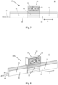
- FIG. 1 to 14 Different channel arrangements according to exemplary embodiments of the present invention are shown. A respective channel arrangement is provided with the reference number 100.
- Fig. 1 shows a first exemplary embodiment of the channel arrangement 100.
- the channel arrangement 100 comprises a device carrier 10 and a cable routing channel 11.
- the cable routing channel 11 is preferably a skirting board or a cable channel or a floor strip.
- the at least one cable routing channel 11 is designed or manufactured from a material different from plastic.
- the cable routing channel 11 can be made, for example, from a wooden material and/or from a glass material and/or from a stone material and/or a ceramic material.
- the equipment carrier 10 is arranged in a vertical orientation on a mounting wall 12 in relation to a longitudinal extent L of the cable routing channel 11.
- the mounting wall 12 can be an interior wall of a building.
- the at least one cable guide channel 11 is preferably arranged on a bottom edge region of the mounting wall 12.
- the equipment carrier 10 is preferably arranged starting from a floor above the cable routing channel 11.
- the device carrier 10 is in the case of Fig. 1 designed to accommodate an electrical installation device 13 designed, for example, as a socket (see Fig. 2 ).
- the device carrier 10 is initially shown without the electrical installation device 13.
- the electrical installation device 13 can be mounted on the mounting wall 12 through the device carrier 10.
- the electrical installation device 13 compared to the Fig. 4 to 6 arranged further above the cable routing channel 11.
- the at least one electrical installation device 13 includes a multiple socket, which in the present case is designed as a triple socket in a horizontal row arrangement (based on the longitudinal extent L).
- the at least one electrical installation device 13 is also designed as a triple socket in a series connection, but in the case shown in a vertical arrangement, based on the longitudinal extent L.
- the equipment carrier 10 has a carrier housing 14 and a channel adapter 15 that is reversibly and detachably connected to the carrier housing 14.
- the channel adapter 15 can be connected to the carrier housing 14, for example via a plug connection.
- the channel adapter 15 covers a front side 16 of the at least one cable routing channel 11, which is designed as a channel cover.
- the channel adapter 15 is adapted to a cross-sectional contour 17 of the cable routing channel 11 at least in sections, ie not necessarily along an entire circumferential contour (see Fig. 1 to 3 and 13 to 14 ).
- the channel adapter 15 can also include a shape, color and/or contour that deviates from the front side 16 (see Fig. 4 to 12 ).
- the cable routing channel 11 comprises, on its inner side facing the mounting wall 12 and opposite the front side 16, a recess 18 which is designed to accommodate at least one electrical cable 19 in order to protect it from the environment to hide or disguise.
- the recess 18 is formed by an inside contour, viewed in the direction of the mounting wall 12.
- the cable routing channel 11 is designed in one piece in the present case, but in other embodiments it can also be designed in two parts and, for example, have a channel base.
- the line cable 19 is designed to supply the at least one electrical installation device 13 with electrical power from an external, unspecified power source.
- the power source can be, for example, a main supply connection in a building and/or a room.
- the channel arrangement 100 can include an additional cable channel 20 (see Fig. 1 to 3 ).
- the cable duct 20 can include a cable duct base 21 and a cable duct cover 22 (see Fig. 3 ).
- the at least one cable routing channel 11 is separated in an area in which the channel adapter 15 is arranged, so that two components of the cable routing channel 11 are spaced apart from one another in the area of the channel adapter 15.
- the cable 19 can be led out of the recess 18 and preferably guided vertically upwards (away from a floor) in the direction of the electrical installation device 13 or the device carrier 10.
- the two components of the cable routing channel 11 can be a single cable routing channel 11, which is separated in this area, or they can be two different cable routing channels, which are only arranged on the mounting wall 12 in this area at a predetermined distance from one another in order to guide the cable 19 upwards out of the recess 18.
- the line cable 19 can preferably be guided through the cable duct 20 in the event that the equipment carrier 10 is further spaced from the line routing duct 11 is, or the cable 19 is led directly out of the recess 18 into the device carrier 10.
- the device carrier 10 comprises a carrier base 23, which is designed to accommodate the at least one electrical installation device 13.
- the carrier housing 14 is designed to accommodate the carrier base 23 and the channel adapter 15 (see Fig. 3 , 6 , 9 and 12 ).
- the carrier base 23 preferably has a recess 18 for receiving the channel adapter 15.
- the electrical installation device 13 further comprises a mounting frame 24 and the support base 23 a connection device 25, which is connected to the mounting frame 24 or is in particular integrally connected to it, the mounting frame 24 being connected to the connection device 25 together with the electrical installation device 13 as a mounting unit.
Landscapes
- Engineering & Computer Science (AREA)
- Architecture (AREA)
- Civil Engineering (AREA)
- Structural Engineering (AREA)
- Details Of Indoor Wiring (AREA)
Applications Claiming Priority (1)
| Application Number | Priority Date | Filing Date | Title |
|---|---|---|---|
| DE202022104859.2U DE202022104859U1 (de) | 2022-08-29 | 2022-08-29 | Kanalanordnung mit einem Leitungsführungskanal und einem Geräteträger |
Publications (1)
| Publication Number | Publication Date |
|---|---|
| EP4333225A1 true EP4333225A1 (fr) | 2024-03-06 |
Family
ID=83447408
Family Applications (1)
| Application Number | Title | Priority Date | Filing Date |
|---|---|---|---|
| EP23192777.3A Pending EP4333225A1 (fr) | 2022-08-29 | 2023-08-22 | Agencement de canal doté d'un canal de guidage de conduite et d'un support d'appareil |
Country Status (2)
| Country | Link |
|---|---|
| EP (1) | EP4333225A1 (fr) |
| DE (1) | DE202022104859U1 (fr) |
Citations (6)
| Publication number | Priority date | Publication date | Assignee | Title |
|---|---|---|---|---|
| EP1571744A1 (fr) * | 2004-03-01 | 2005-09-07 | Canalplast S.P.A. | Boíte modulaire électrique avec une ségrégation et une séparation du passage pour l'usage de câbles électriques et de signal |
| DE202004013181U1 (de) | 2004-08-24 | 2006-01-05 | Tehalit Gmbh & Co. Kg | Stoßkaschierung für Geräteträger an Sockelleistenkanälen |
| WO2006076466A2 (fr) * | 2005-01-13 | 2006-07-20 | The Wiremold Company | Canalisation modulaire avec socle et diviseur integral |
| US20070256851A1 (en) * | 2006-05-03 | 2007-11-08 | Tom Kennedy | Apparatus and method for concealing conduit |
| DE202017102843U1 (de) * | 2017-05-11 | 2017-07-27 | Ggk Gmbh & Co. Kg | Steckdosenanschlusseinrichtung |
| EP3217497A1 (fr) | 2016-03-08 | 2017-09-13 | GGK GmbH & Co. KG | Support d'appareil |
-
2022
- 2022-08-29 DE DE202022104859.2U patent/DE202022104859U1/de active Active
-
2023
- 2023-08-22 EP EP23192777.3A patent/EP4333225A1/fr active Pending
Patent Citations (6)
| Publication number | Priority date | Publication date | Assignee | Title |
|---|---|---|---|---|
| EP1571744A1 (fr) * | 2004-03-01 | 2005-09-07 | Canalplast S.P.A. | Boíte modulaire électrique avec une ségrégation et une séparation du passage pour l'usage de câbles électriques et de signal |
| DE202004013181U1 (de) | 2004-08-24 | 2006-01-05 | Tehalit Gmbh & Co. Kg | Stoßkaschierung für Geräteträger an Sockelleistenkanälen |
| WO2006076466A2 (fr) * | 2005-01-13 | 2006-07-20 | The Wiremold Company | Canalisation modulaire avec socle et diviseur integral |
| US20070256851A1 (en) * | 2006-05-03 | 2007-11-08 | Tom Kennedy | Apparatus and method for concealing conduit |
| EP3217497A1 (fr) | 2016-03-08 | 2017-09-13 | GGK GmbH & Co. KG | Support d'appareil |
| DE202017102843U1 (de) * | 2017-05-11 | 2017-07-27 | Ggk Gmbh & Co. Kg | Steckdosenanschlusseinrichtung |
Also Published As
| Publication number | Publication date |
|---|---|
| DE202022104859U1 (de) | 2022-09-08 |
Similar Documents
| Publication | Publication Date | Title |
|---|---|---|
| DE19860812B4 (de) | Kabelkanalsystem zum Verlegen von Lichtwellenleiterkabeln | |
| DE1216957B (de) | Kabelfuehrungskanal | |
| DE10057122A1 (de) | Kabelkanalsystem mit getrennten Leitungen für Stromleiter und Datenübertragungsleiter | |
| DE2145453A1 (de) | Tisch mit einer Anordnung zum Aufnehmen von Geräteanschlußkabeln | |
| EP0446875B1 (fr) | Boîtiers de protection pour dispositifs optiques | |
| EP2360330A2 (fr) | Plinthe et connecteur de plinthes | |
| EP0159554A2 (fr) | Unité de montage d'appareil pour plinthes formant des canalisations d'installation | |
| DE102019122500A1 (de) | Wand- oder Bodenleiste mit integriertem Kabelkanal und Verfahren zur Installation einer solchen Wand- oder Bodenleiste | |
| DE102004045964A1 (de) | Kabelauslass-Element, Kabelauslass-Vorrichtung, Kabelauslass-Anordnung, Verfahren zum Herstellen eines Kabelauslass-Elements und Verwendung eines Kabelauslass-Elements in einem Flugzeug | |
| AT510645B1 (de) | Eckprofilsystem | |
| EP2240985B1 (fr) | Boite d'installation electrique, notamment boite de distribution, pour montage apparent | |
| EP4333225A1 (fr) | Agencement de canal doté d'un canal de guidage de conduite et d'un support d'appareil | |
| DE202006006453U1 (de) | Elektro-Installationssystem | |
| DE202007013698U1 (de) | Wandkanalinstallation mit einem im Mauerstein eingesetzten Kabelkanal für Gebäudeinnenräume | |
| DE20113696U1 (de) | Installationskanal | |
| DE8701537U1 (de) | Verbindungsvorrichtung für Anbaukanäle mit Verkleidungselementen | |
| EP0582945A2 (fr) | Elément de mur multifonctionnel pour équipements de bureau et d'autres équipements de poste de travail | |
| EP2872712B1 (fr) | Kit de construction destiné à la réalisation de revêtements | |
| EP3217497B1 (fr) | Support d'appareil | |
| DE10325938B4 (de) | Kleinverteiler | |
| EP0924829B1 (fr) | Dispositif de connexion pour conduites de câbles | |
| EP3217495A1 (fr) | Goulotte electrique | |
| DE9310439U1 (de) | Kabelkanalsystem für elektrische Leitungen | |
| DE202017102712U1 (de) | Mauerstein sowie eine von einer Vielzahl von Mauersteinen gebildete Wand | |
| DE202019106584U1 (de) | Wandung eines Hauses, insbesondere eines Fertighauses |
Legal Events
| Date | Code | Title | Description |
|---|---|---|---|
| PUAI | Public reference made under article 153(3) epc to a published international application that has entered the european phase |
Free format text: ORIGINAL CODE: 0009012 |
|
| STAA | Information on the status of an ep patent application or granted ep patent |
Free format text: STATUS: THE APPLICATION HAS BEEN PUBLISHED |
|
| AK | Designated contracting states |
Kind code of ref document: A1 Designated state(s): AL AT BE BG CH CY CZ DE DK EE ES FI FR GB GR HR HU IE IS IT LI LT LU LV MC ME MK MT NL NO PL PT RO RS SE SI SK SM TR |
|
| STAA | Information on the status of an ep patent application or granted ep patent |
Free format text: STATUS: REQUEST FOR EXAMINATION WAS MADE |
|
| 17P | Request for examination filed |
Effective date: 20240627 |
|
| RBV | Designated contracting states (corrected) |
Designated state(s): AL AT BE BG CH CY CZ DE DK EE ES FI FR GB GR HR HU IE IS IT LI LT LU LV MC ME MK MT NL NO PL PT RO RS SE SI SK SM TR |
|
| STAA | Information on the status of an ep patent application or granted ep patent |
Free format text: STATUS: EXAMINATION IS IN PROGRESS |
|
| 17Q | First examination report despatched |
Effective date: 20250916 |