EP4336005A1 - Unité de détection électronique pour une poignée fixée sur une porte de voiture - Google Patents
Unité de détection électronique pour une poignée fixée sur une porte de voiture Download PDFInfo
- Publication number
- EP4336005A1 EP4336005A1 EP22214669.8A EP22214669A EP4336005A1 EP 4336005 A1 EP4336005 A1 EP 4336005A1 EP 22214669 A EP22214669 A EP 22214669A EP 4336005 A1 EP4336005 A1 EP 4336005A1
- Authority
- EP
- European Patent Office
- Prior art keywords
- handle
- sensing unit
- sensor
- car door
- car
- Prior art date
- Legal status (The legal status is an assumption and is not a legal conclusion. Google has not performed a legal analysis and makes no representation as to the accuracy of the status listed.)
- Granted
Links
Images


Classifications
-
- E—FIXED CONSTRUCTIONS
- E05—LOCKS; KEYS; WINDOW OR DOOR FITTINGS; SAFES
- E05B—LOCKS; ACCESSORIES THEREFOR; HANDCUFFS
- E05B81/00—Power-actuated vehicle locks
- E05B81/54—Electrical circuits
- E05B81/64—Monitoring or sensing, e.g. by using switches or sensors
- E05B81/76—Detection of handle operation; Detection of a user approaching a handle; Electrical switching actions performed by door handles
- E05B81/77—Detection of handle operation; Detection of a user approaching a handle; Electrical switching actions performed by door handles comprising sensors detecting the presence of the hand of a user
-
- E—FIXED CONSTRUCTIONS
- E05—LOCKS; KEYS; WINDOW OR DOOR FITTINGS; SAFES
- E05B—LOCKS; ACCESSORIES THEREFOR; HANDCUFFS
- E05B81/00—Power-actuated vehicle locks
- E05B81/54—Electrical circuits
- E05B81/64—Monitoring or sensing, e.g. by using switches or sensors
-
- B—PERFORMING OPERATIONS; TRANSPORTING
- B60—VEHICLES IN GENERAL
- B60J—WINDOWS, WINDSCREENS, NON-FIXED ROOFS, DOORS, OR SIMILAR DEVICES FOR VEHICLES; REMOVABLE EXTERNAL PROTECTIVE COVERINGS SPECIALLY ADAPTED FOR VEHICLES
- B60J5/00—Doors
- B60J5/04—Doors arranged at the vehicle sides
-
- B—PERFORMING OPERATIONS; TRANSPORTING
- B60—VEHICLES IN GENERAL
- B60R—VEHICLES, VEHICLE FITTINGS, OR VEHICLE PARTS, NOT OTHERWISE PROVIDED FOR
- B60R11/00—Arrangements for holding or mounting articles, not otherwise provided for
-
- E—FIXED CONSTRUCTIONS
- E05—LOCKS; KEYS; WINDOW OR DOOR FITTINGS; SAFES
- E05B—LOCKS; ACCESSORIES THEREFOR; HANDCUFFS
- E05B79/00—Mounting or connecting vehicle locks or parts thereof
- E05B79/02—Mounting of vehicle locks or parts thereof
-
- E—FIXED CONSTRUCTIONS
- E05—LOCKS; KEYS; WINDOW OR DOOR FITTINGS; SAFES
- E05B—LOCKS; ACCESSORIES THEREFOR; HANDCUFFS
- E05B79/00—Mounting or connecting vehicle locks or parts thereof
- E05B79/02—Mounting of vehicle locks or parts thereof
- E05B79/06—Mounting of handles, e.g. to the wing or to the lock
-
- E—FIXED CONSTRUCTIONS
- E05—LOCKS; KEYS; WINDOW OR DOOR FITTINGS; SAFES
- E05B—LOCKS; ACCESSORIES THEREFOR; HANDCUFFS
- E05B81/00—Power-actuated vehicle locks
- E05B81/54—Electrical circuits
- E05B81/64—Monitoring or sensing, e.g. by using switches or sensors
- E05B81/76—Detection of handle operation; Detection of a user approaching a handle; Electrical switching actions performed by door handles
-
- E—FIXED CONSTRUCTIONS
- E05—LOCKS; KEYS; WINDOW OR DOOR FITTINGS; SAFES
- E05B—LOCKS; ACCESSORIES THEREFOR; HANDCUFFS
- E05B85/00—Details of vehicle locks not provided for in groups E05B77/00 - E05B83/00
- E05B85/10—Handles
-
- B—PERFORMING OPERATIONS; TRANSPORTING
- B60—VEHICLES IN GENERAL
- B60R—VEHICLES, VEHICLE FITTINGS, OR VEHICLE PARTS, NOT OTHERWISE PROVIDED FOR
- B60R11/00—Arrangements for holding or mounting articles, not otherwise provided for
- B60R2011/0001—Arrangements for holding or mounting articles, not otherwise provided for characterised by position
- B60R2011/0003—Arrangements for holding or mounting articles, not otherwise provided for characterised by position inside the vehicle
- B60R2011/0019—Side or rear panels
- B60R2011/0021—Doors
-
- E—FIXED CONSTRUCTIONS
- E05—LOCKS; KEYS; WINDOW OR DOOR FITTINGS; SAFES
- E05B—LOCKS; ACCESSORIES THEREFOR; HANDCUFFS
- E05B63/00—Locks or fastenings with special structural characteristics
- E05B63/0056—Locks with adjustable or exchangeable lock parts
Definitions
- the present invention concerns an electronic sensing unit for a handle attached on a car door.
- sensing unit can however result in a decrease of the user experience quality since the sensing unit could be located in a place that is not intuitive for the user.
- sensing unit in a handle could also lead to another opening method that requires practice for the user. For example, it could be necessary to push or touch a button and then pull the door which implies realizing a two different movements in a precise order to open the door.
- the present invention aims to solve all or some of the disadvantages mentioned above.
- the present invention relates to an electronic sensing unit for a handle attached on a car door, the electronic sensing unit comprises:
- This provision enables to have a sensor that is fixed on the external side of the car and in the same time that is biased by a constraint applied to the handle. Given that the sensor cooperates simultaneously with the part of the car door and with the handle, the sensor can measure a constraint and therefore a command from a user pushing or pulling the handle.
- the external side refers to the side of the part of the car door facing the outside of the car.
- the part comprises an internal side facing the interior of the car.
- the handle is an outside handle of the car for example on the driver side.
- car it is understood every kind of vehicle in the automotive industry including bus, truck, personal vehicles etc.
- the senor includes at least one strain gauge, said at least one strain gauge being configured to be deformed when the constraint is applied to the handle.
- the second element of the fixing mechanism enables to transmit the constraint applied on the handle so as to deform the at least one strain gauge. It thus appears that when a user push or pulls the handle of the car, it implies the deformation of the at least one strain gauge.
- the at least one sensor is configured to close and to release a locking mechanism of the car door.
- a compressing pressure is applied to the sensor transversally to the reference plane, namely when pushing the car door towards a closed position, a locking command is acquired.
- a releasing command is acquired.
- the user in only one movement, the user can unlock and open the car door or close and lock the car door.
- the at least one strain gauge may be a full-bridge strain gauge or a half-bridge strain gauge.
- the handle is an outside handle of the car for example on the driver side.
- car it is understood every kind of vehicle in the automotive industry including bus, truck, personal vehicles etc.
- the senor comprises a support on which the at least one strain gauge is attached, the support being configured to be attached on the external side or on an intermediate part mounted on the external side, the support extending parallel to the reference plane.
- the support is substantially planar and extending parallel to the reference plane facilitates the insertion of the sensor between the handle and the external side.
- each sensor comprises two strain gauges mounted on the support.
- the support is constituted of a metal material.
- the support at least one attaching portion configured to be fixed to the part of the car thanks to a corresponding third element of the fixing mechanism.
- the at least one attaching portion is an orifice or a slot configured for receiving the corresponding third element which is for example a screw, possibly with mounting ring(s).
- the support presents two attaching portions, the strain gauges being located between the two attaching portions according to a longitudinal direction of the support.
- the first element extends according to a main direction that is configured to be transversal to the reference plane when installed, the part of the car door and the support presenting each a through opening for the passage of the first element.
- the first element comprises a head configured to cooperate with an internal surface of the part of the car door opposed to the external side.
- the opening of the support is located between the two strain gauges according to the longitudinal direction of the support.
- the first element is a screw.
- a screw is an efficient way to secure the support on the external side or on an intermediate part mounted on the external side.
- the second element presents a form complementary with a recess in the handle so that there is a cooperation by complementarity of form.
- the complementarity of form is important as it enables the first element to move together with the handle when a user is pushing or pulling the handle.
- the second element is a nut.
- said nut is configured to cooperate with the screw to secure de support on the external side.
- the electronic sensing unit comprises two distinct sensors and two corresponding fixing mechanisms.
- This provision enables to obtain a more accurate signal.
- the present invention also concerns a car access assembly comprising the handle mounted on the car door, the car access assembly also comprising an electronic sensing unit as described above.
- the car access assembly also comprises the car door.
- the present invention also concerns a car comprising at least one car access assembly as described above.
- the car access assembly comprises an additional fixing element for fixing the handle on the part of the car.
- the additional fixing element is a screw configured to be cooperating with the handle and with the part of the car, said screw presenting an axis deviating from the main direction transversally to the reference plane.
- said deviation is 45° more or less 10° or 90° more and less 10°.
- the handle comprises a guiding leg extending farther than the internal face of the part of the car door, the guiding leg being configured for guiding a signal transmitting device of the electronic sensing unit connected the sensor.
- the guiding leg serves as a protection means for the signal transmitting device connected to the sensor.
- the part of the car presents a notch for the passage of the guiding leg from the external side to a location farther than the internal surface of the part of the car.
- the guiding leg presents channel(s) for the signal transmitting device guiding.
- the signal transmitting device comprises electrical wire(s) or flexible printed circuit board(s) configured to transmit a signal from the sensor.
- Wires can be shielded or not.
- the car access system also comprises an electronic control unit, said electronic control unit comprising a connector configured to cooperate with the signal transmitting device, the guiding leg presenting a housing for receiving said electronic control unit.
- the electronic control unit comprises a rigid printed circuit box configured to track the measures from the sensor.
- the electronic control unit comprises an outlet cable to be connected to the car information management system.
- the electronic control unit can comprise an outlet connector, for example accessible from the outside the housing of electronic control unit.
- the electronic control unit may comprise a housing realized by potting for protecting the inner components.
- the outlet connector can be outside of the potting.
- an electronic sensing unit 1 for a handle 3 attached on a car door 5 is depicted.
- the electronic sensing unit 1 comprises two sensors 7 attached on an external side 9 of a part 11 of the car door 5 extending according to a reference plane 13.
- the electronic sensing unit 1 comprises a fixing mechanism 15 for each sensor 7, the fixing mechanism 15 comprising a first element 17 and a second element 19 configured to cooperate together; the first element 17 being also configured to cooperate with the part 11 of the car door 5 and the sensor 7 or with the handle 3.
- the second element 19 is configured to cooperate with the handle 3 or with the part 11 of the car door 5 and the sensor 7 so that a constraint applied to the handle 3 is transmitted to the sensors 7 for detection of a command.
- the external side 9 refers to the side of the part 11 of the car door 5 facing the outside of the car.
- the part 11 comprises an internal side facing the interior of the car.
- the handle 3 is an outside handle of the car for example on the driver side.
- car it is understood every kind of vehicle in the automotive industry including bus, truck, personal vehicles etc.
- Each sensor 7 includes at least one strain gauge 21, said at least one strain gauge 21 being configured to be deformed when the constraint is applied to the handle 3.
- the second element 19 of the fixing mechanism 15 enables to transmit the constraint applied on the handle so as to deform the at least one strain gauge 21. It thus appears that when a user push or pulls the handle 3 of the car, it implies the deformation of the at least one strain gauge 21.
- Each sensor 7 is configured to close and to release a locking mechanism of the car door 5.
- the user in only one movement, the user can unlock and open the car door 5 or close and lock the car door 5.
- the at least one strain gauge 21 may be a full-bridge strain gauge or a half-bridge strain gauge.
- the handle 3 is an outside handle of the car for example on the driver side.
- car it is understood every kind of vehicle in the automotive industry including bus, truck, personal vehicles etc.
- Each sensor 7 comprises a support 23 on which the at least one strain gauge 21 is attached, the support 23 being configured to be attached on the external side 9 or on an intermediate part mounted on the external side 9, the support 23 extending parallel to the reference plane 13.
- the support 23 is substantially planar and extending parallel to the reference plane 13 facilitates the insertion of the sensors 7 between the handle 3 and the external side 9.
- Each sensor 7 comprises two strain gauges 21 mounted on the support 23.
- the support 23 is constituted of a metal material.
- the support 23 presents at least one attaching portion 25 configured to be fixed to the part 11 of the car thanks to a corresponding third element 27 of the fixing mechanism 15.
- the at least one attaching portion 25 is an orifice or a slot configured for receiving the corresponding third element 27 which is for example a screw, possibly with mounting ring(s).
- the support 23 presents two attaching portions 25, the strain gauges 21 being located between the two attaching portions 25 according to a longitudinal direction 29 of the support 23.
- Each first element 17 extends according to a main direction 31 that is configured to be transversal to the reference plane 13 when installed, the part 11 of the car door 5 and the support 23 presenting each a through opening for the passage of the first element 17.
- the first element 17 comprises a head 33 configured to cooperate with the internal surface of the part 11 of the car door 5 opposed to the external side 9.
- the opening of the support 23 is located between the two strain gauges 21 according to the longitudinal direction 29 of the support 23.
- the first element 17 is a screw.
- a screw is an efficient way to secure the support 23 on the external side 9 or on an intermediate part mounted on the external side 9.
- the second element 19 presents a form complementary with a recess 35 in the handle 3 so that there is a cooperation by complementarity of form.
- the complementarity of form is important as it enables the first element 17 to move together with the handle 3 when a user is pushing or pulling the handle 3.
- the second element 19 is a nut, said nut being configured to cooperate with the screw to secure the support 23 on the external side 9.
- the electronic sensing unit 1 comprises two distinct sensors 7 and two corresponding fixing mechanisms 15.
- a car access assembly 37 comprises the handle 3 mounted on the car door 5, the car access assembly 37 also comprising an electronic sensing unit 1 described above.
- the handle can include a gasket 38 to be inserted between said handle 3 and the external side 9.
- the car access assembly 37 also comprises the car door 5. There is also a car comprising at least one car access assembly 37 as described above.
- the car access assembly comprises an additional fixing element 39 for fixing the handle 3 on the part 11 of the car.
- the additional fixing element 39 is a screw configured to be cooperating with the handle 3 and with the part 11 of the car, said screw presenting an axis deviating from the main direction 31 transversally to the reference plane 13.
- said deviation is 45° more or less 10° as in figure 1 or 90° more and less 10° as in figure 2 .
- the handle 3 comprises a guiding leg 41 extending farther than the internal face of the part 11 of the car, the guiding leg 41 being configured for guiding a signal transmitting device 43 connected the sensors 7.
- the guiding leg 41 serves as a protection means for the signal transmitting device 43 connected to the sensors 7.
- the part 11 of the car presents a notch 45 in figure 2 for the passage of the guiding leg 41 from the external side 9 to a location farther than the internal surface of the part 11 of the car.
- the guiding leg 41 presents channels 47 for the signal transmitting device 43 guiding.
- the signal transmitting device 43 comprises electrical wires in the variant of figure 5 or flexible printed circuit boards configured to transmit a signal from the sensors 7 as in figures 3 and 4 . Wires can be shielded or not.
- the car access system 1 may also comprises an electronic control unit 49 as in figures 3 and 4 variants, said electronic control unit 49 comprising a connector configured to cooperate with the signal transmitting device 43, the guiding leg 41 presenting a housing for receiving said electronic control unit 49.
- the electronic control unit 49 comprises a rigid printed circuit box configured to track the measures from the sensors 7.
- the electronic control unit 49 may comprise an outlet cable 51 as in figure 3 to be connected to the car information management system.
- the electronic control unit 49 can comprise an outlet connector 53 as in figure 4 variant, which is accessible from the outside of the housing of electronic control unit 49.
- the electronic control unit 49 may comprise a housing realized by potting for protecting the inner components.
- the outlet connector 53 can be outside of the potting.
- FIGs 6 and 7 shows another variant of the handle 3, in which the handle 3 is attached from the external side 9.
- through holes 60 are arranged in the handle 3 so that the handle 3 can be fixed from the external side 9 of the car door 5.
- the through holes 60 are closed by a cover 61 after the handle 3 has been fixed.
- the cover 61 covers all through holes 60 in the handle 3 which are present for fixing the handle 3 to the car door 5.
- the cover 61 is fitted on the handle 3 from an external side 62 thereof, the external side 62 of the handle 3 referring to the side of the handle 3 facing away from the car door 5.
- the access assembly 37 comprises a gasket body 63, the gasket body 63 being mounted on the external side 9 of the car door 5 and in particular being fixedly connected to the car door 5.
- the gasket body 63 can hold the second elements 19 for fixing the handle 3, as well as the holder 23 with the sensors 7, the second element 19 having a shape complementary to a recess 35 in the gasket body 63.
- the handle 3 may also have a clearance 64 through which a hand of a person may pass.
- the handle 3 has at least two through holes or recesses 60, 60' which are arranged in alignment one behind the other. These through holes 60, 60' are each covered by a cover 61, 61'.
- the first cover 61 as well as the first through hole 60 are arranged at the external side 62 of the handle 3, and the second cover 61' as well as the second through hole 60' are arranged between the external side 62 of the handle 3 and the car door 5. This allows a simple assembly to be performed by inserting an assembly tool through the first through hole 60 and second through hole 60'.
- the two covers 61, 61' are mounted, which cover the through holes 60, 60' and allow an aesthetic appearance.
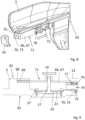
- Figures 8 and 9 shows another variation of the handle 3.
- Figure 8 shows the inner side 65 of the handle 3, where the inner side 65 refers to the side of the handle 3 facing the car door 5.
- the handle 3 has a mounting aid 66, which preferably consists of an elongated plate 67, which is connected to the handle 3.
- the handle 3 has a slot 68 on one side, into which a first end 69 of the plate 67 is inserted.
- the slot 68 is thereby configured in such a way that the plate 67 is fixed in its position and can be displaced in the longitudinal direction of the handle 3, in particular it can be displaced in the direction of the reference plane 13.
- the second end 70 of the plate 67 is connected, in particular screwed, to the handle 3.
- the plate 67 can be angled on one side.
- the plate 67 has an elongated hole 72 in the elongated region 71 and a recess or bore 74 in the angled region 73. Due to the sheet 67, the handle 3 can be displaced in the longitudinal direction, in particular in the direction of the reference plane 13, in order to compensate tolerances.
- the recess 74 at the angled region 73 of the plate 67 serves to fix the plate 67 to the screw 75, which is screwed into the handle 3.
- the screw 75 can have a circumferential gap 76, in which, in the area of the recess 74, the plate 67 is fixed. If the screw 75 is unscrewed or screwed in, the position of the handle 3 is adjusted in the longitudinal direction.
- a tolerance compensation element 77 is arranged in the handle 3 for this purpose, into which the screw 75 is screwed.
- a through hole or recess is arranged in the car door 5, through which the first element 17, in particular a screw, is inserted. This fixes the position of the first element 17 to the car door 5.
- the handle 3 is mounted on the car door 5 and the first element 17 is pre-fixed. Then, the handle 3 can be moved in the longitudinal direction until it is exactly aligned, by screwing in or unscrewing the screw 75. Subsequently, the first element 17 is screwed tight so that the handle 3 is fixed.
- the plate 67 has a fluting 78 in the area of the elongated hole 72, so that slipping or loosening of the handle 3 is impossible. After the handle 3 has been mounted, it can be advantageous if a side cover 79 is attached to the handle 3 in order to cover the angled area 73 of the plate 67.
Landscapes
- Engineering & Computer Science (AREA)
- Mechanical Engineering (AREA)
- Lock And Its Accessories (AREA)
Applications Claiming Priority (1)
| Application Number | Priority Date | Filing Date | Title |
|---|---|---|---|
| EP22194179.2A EP4336003B1 (fr) | 2022-09-06 | 2022-09-06 | Ensemble d'accès de vehicule avec unité de détection électronique pour une poignée fixée sur une portière de voiture |
Publications (2)
| Publication Number | Publication Date |
|---|---|
| EP4336005A1 true EP4336005A1 (fr) | 2024-03-13 |
| EP4336005B1 EP4336005B1 (fr) | 2025-03-05 |
Family
ID=83228959
Family Applications (2)
| Application Number | Title | Priority Date | Filing Date |
|---|---|---|---|
| EP22194179.2A Active EP4336003B1 (fr) | 2022-09-06 | 2022-09-06 | Ensemble d'accès de vehicule avec unité de détection électronique pour une poignée fixée sur une portière de voiture |
| EP22214669.8A Active EP4336005B1 (fr) | 2022-09-06 | 2022-12-19 | Dispositif d'accès de voiture |
Family Applications Before (1)
| Application Number | Title | Priority Date | Filing Date |
|---|---|---|---|
| EP22194179.2A Active EP4336003B1 (fr) | 2022-09-06 | 2022-09-06 | Ensemble d'accès de vehicule avec unité de détection électronique pour une poignée fixée sur une portière de voiture |
Country Status (5)
| Country | Link |
|---|---|
| US (1) | US20240076913A1 (fr) |
| EP (2) | EP4336003B1 (fr) |
| JP (1) | JP2024037167A (fr) |
| CN (1) | CN117661935A (fr) |
| ES (1) | ES3017797T3 (fr) |
Cited By (1)
| Publication number | Priority date | Publication date | Assignee | Title |
|---|---|---|---|---|
| EP4642010A1 (fr) | 2024-04-25 | 2025-10-29 | Metabowerke GmbH | Système de suivi |
Families Citing this family (1)
| Publication number | Priority date | Publication date | Assignee | Title |
|---|---|---|---|---|
| DE102024123182A1 (de) * | 2024-08-14 | 2026-02-19 | Bayerische Motoren Werke Aktiengesellschaft | Griffelement für ein Flügelelement eines Fahrzeugs, Flügelelement für ein Fahrzeug sowie Fahrzeug |
Citations (5)
| Publication number | Priority date | Publication date | Assignee | Title |
|---|---|---|---|---|
| US20140292004A1 (en) * | 2013-04-01 | 2014-10-02 | Magna Mirrors Of America, Inc. | Vehicle door handle system |
| US20150123409A1 (en) * | 2013-11-05 | 2015-05-07 | GM Global Technology Operations LLC | Fixed outside handle with multi-functions and protected switches |
| US20160123045A1 (en) * | 2014-10-29 | 2016-05-05 | Adac Plastics, Inc. | Decoupled handle switch |
| WO2017019760A1 (fr) * | 2015-07-28 | 2017-02-02 | Huf North America Automotive Parts Mfg. Corp. | Ensemble d'accès à un véhicule ayant un transducteur piézoélectrique pour fournir un retour tactile et une production de son |
| DE102016123724A1 (de) * | 2016-12-07 | 2018-06-07 | Witte Automotive Gmbh | Türgriffsystem |
Family Cites Families (10)
| Publication number | Priority date | Publication date | Assignee | Title |
|---|---|---|---|---|
| EP1238177B2 (fr) * | 1999-11-29 | 2009-03-25 | Brose Schliesssysteme GmbH & Co. KG | Dispositif de poignee exterieure de porte |
| DE10031664C1 (de) * | 2000-06-29 | 2002-01-03 | Kiekert Ag | Betätigungseinrichtung |
| JP4161664B2 (ja) * | 2002-09-27 | 2008-10-08 | アイシン精機株式会社 | 車両用ドアハンドル装置 |
| JP4342207B2 (ja) * | 2003-04-22 | 2009-10-14 | アイシン精機株式会社 | 車両用ドアハンドル装置 |
| FR2857742B1 (fr) * | 2003-07-15 | 2005-10-28 | Arvinmeritor Light Vehicle Sys | Module capteur pour commande de deverrouillage d'ouvrant automobile |
| DE10348719A1 (de) * | 2003-10-16 | 2005-05-12 | Huf Huelsbeck & Fuerst Gmbh | Türaußengriff, insbesondere für Fahrzeuge |
| DE102004019571B4 (de) * | 2004-04-22 | 2006-02-23 | Huf Hülsbeck & Fürst Gmbh & Co. Kg | Vorrichtung zum Betätigen einer elektrischen oder mechanischen Schließeinrichtung an einer Tür und/oder einer Klappe eines Fahrzeugs |
| DE102007028898A1 (de) * | 2007-06-22 | 2008-12-24 | Huf Hülsbeck & Fürst Gmbh & Co. Kg | Vorrichtung zum Auslösen von Funktionen in einem Fahrzeug |
| US20160251880A1 (en) * | 2013-03-15 | 2016-09-01 | Adac Plastic, Inc. | Control for vehicle closures |
| EP4461912B1 (fr) * | 2023-05-09 | 2025-10-15 | Minebea AccessSolutions Italia S.p.A. | Poignée extérieure de véhicule automobile commandée par un capteur de jauge de contrainte |
-
2022
- 2022-09-06 EP EP22194179.2A patent/EP4336003B1/fr active Active
- 2022-12-19 ES ES22214669T patent/ES3017797T3/es active Active
- 2022-12-19 EP EP22214669.8A patent/EP4336005B1/fr active Active
-
2023
- 2023-09-04 CN CN202311133296.XA patent/CN117661935A/zh active Pending
- 2023-09-05 JP JP2023143321A patent/JP2024037167A/ja active Pending
- 2023-09-05 US US18/461,158 patent/US20240076913A1/en active Pending
Patent Citations (5)
| Publication number | Priority date | Publication date | Assignee | Title |
|---|---|---|---|---|
| US20140292004A1 (en) * | 2013-04-01 | 2014-10-02 | Magna Mirrors Of America, Inc. | Vehicle door handle system |
| US20150123409A1 (en) * | 2013-11-05 | 2015-05-07 | GM Global Technology Operations LLC | Fixed outside handle with multi-functions and protected switches |
| US20160123045A1 (en) * | 2014-10-29 | 2016-05-05 | Adac Plastics, Inc. | Decoupled handle switch |
| WO2017019760A1 (fr) * | 2015-07-28 | 2017-02-02 | Huf North America Automotive Parts Mfg. Corp. | Ensemble d'accès à un véhicule ayant un transducteur piézoélectrique pour fournir un retour tactile et une production de son |
| DE102016123724A1 (de) * | 2016-12-07 | 2018-06-07 | Witte Automotive Gmbh | Türgriffsystem |
Cited By (1)
| Publication number | Priority date | Publication date | Assignee | Title |
|---|---|---|---|---|
| EP4642010A1 (fr) | 2024-04-25 | 2025-10-29 | Metabowerke GmbH | Système de suivi |
Also Published As
| Publication number | Publication date |
|---|---|
| EP4336003B1 (fr) | 2025-10-08 |
| EP4336003A1 (fr) | 2024-03-13 |
| JP2024037167A (ja) | 2024-03-18 |
| EP4336005B1 (fr) | 2025-03-05 |
| CN117661935A (zh) | 2024-03-08 |
| ES3017797T3 (en) | 2025-05-13 |
| US20240076913A1 (en) | 2024-03-07 |
Similar Documents
| Publication | Publication Date | Title |
|---|---|---|
| EP4336005B1 (fr) | Dispositif d'accès de voiture | |
| US11365570B2 (en) | Door handle assembly for a motor vehicle | |
| EP2998166B1 (fr) | Système de fixation utilisable pour des connecteurs | |
| US5944534A (en) | Functional module | |
| CN112928715A (zh) | 电气连接箱以及线束 | |
| CN112384671A (zh) | 车门的外把手装置 | |
| CN112928716A (zh) | 电气连接箱以及线束 | |
| JP4283050B2 (ja) | 車両用フィニッシャー | |
| US7597364B2 (en) | Door handle device for vehicle | |
| KR20090064954A (ko) | 화물차량의 안전 공구함 | |
| EP4336004B1 (fr) | Ensemble d'accès de voiture comprenant une poignée de portière de voiture | |
| US5477712A (en) | Automobile anit-theft guard plate | |
| EP4155488A1 (fr) | Dispositif de détection et système de détection d'activation sur au moins la fonction d'un appareil, et appareil comprenant le système de détection | |
| CN111971441A (zh) | 用于门或罩盖的把手装置 | |
| EP3760821B1 (fr) | Base de montage pour un capteur de poignée de porte | |
| US9657764B2 (en) | Fastening device and method for fastening an element in a keyhole-shaped cutout in a wall | |
| JP2024035826A (ja) | 自動車用ドアのセンサーとして使用される歪ゲージモジュールを有するハンドル | |
| EP3244492B1 (fr) | Ensemble de connexion | |
| JP4966845B2 (ja) | 車両用センサの取付構造 | |
| CN111919008A (zh) | 把手装置 | |
| EP4512982A1 (fr) | Ensemble d'accès pour voiture avec deux jauges de contrainte orientées différemment | |
| US7488179B2 (en) | Component holder | |
| CN113266220B (zh) | 一种车门把手结构及车辆 | |
| KR20000053777A (ko) | 도어록에 내장된 전원 연결 장치 | |
| JP2025025146A (ja) | 配線器具取付枠 |
Legal Events
| Date | Code | Title | Description |
|---|---|---|---|
| PUAI | Public reference made under article 153(3) epc to a published international application that has entered the european phase |
Free format text: ORIGINAL CODE: 0009012 |
|
| STAA | Information on the status of an ep patent application or granted ep patent |
Free format text: STATUS: REQUEST FOR EXAMINATION WAS MADE |
|
| 17P | Request for examination filed |
Effective date: 20221219 |
|
| AK | Designated contracting states |
Kind code of ref document: A1 Designated state(s): AL AT BE BG CH CY CZ DE DK EE ES FI FR GB GR HR HU IE IS IT LI LT LU LV MC ME MK MT NL NO PL PT RO RS SE SI SK SM TR |
|
| GRAP | Despatch of communication of intention to grant a patent |
Free format text: ORIGINAL CODE: EPIDOSNIGR1 |
|
| STAA | Information on the status of an ep patent application or granted ep patent |
Free format text: STATUS: GRANT OF PATENT IS INTENDED |
|
| INTG | Intention to grant announced |
Effective date: 20241029 |
|
| GRAS | Grant fee paid |
Free format text: ORIGINAL CODE: EPIDOSNIGR3 |
|
| GRAA | (expected) grant |
Free format text: ORIGINAL CODE: 0009210 |
|
| STAA | Information on the status of an ep patent application or granted ep patent |
Free format text: STATUS: THE PATENT HAS BEEN GRANTED |
|
| AK | Designated contracting states |
Kind code of ref document: B1 Designated state(s): AL AT BE BG CH CY CZ DE DK EE ES FI FR GB GR HR HU IE IS IT LI LT LU LV MC ME MK MT NL NO PL PT RO RS SE SI SK SM TR |
|
| REG | Reference to a national code |
Ref country code: GB Ref legal event code: FG4D |
|
| REG | Reference to a national code |
Ref country code: CH Ref legal event code: EP |
|
| REG | Reference to a national code |
Ref country code: IE Ref legal event code: FG4D |
|
| REG | Reference to a national code |
Ref country code: DE Ref legal event code: R096 Ref document number: 602022011397 Country of ref document: DE |
|
| REG | Reference to a national code |
Ref country code: ES Ref legal event code: FG2A Ref document number: 3017797 Country of ref document: ES Kind code of ref document: T3 Effective date: 20250513 |
|
| PG25 | Lapsed in a contracting state [announced via postgrant information from national office to epo] |
Ref country code: RS Free format text: LAPSE BECAUSE OF FAILURE TO SUBMIT A TRANSLATION OF THE DESCRIPTION OR TO PAY THE FEE WITHIN THE PRESCRIBED TIME-LIMIT Effective date: 20250605 |
|
| PG25 | Lapsed in a contracting state [announced via postgrant information from national office to epo] |
Ref country code: FI Free format text: LAPSE BECAUSE OF FAILURE TO SUBMIT A TRANSLATION OF THE DESCRIPTION OR TO PAY THE FEE WITHIN THE PRESCRIBED TIME-LIMIT Effective date: 20250305 |
|
| REG | Reference to a national code |
Ref country code: NL Ref legal event code: MP Effective date: 20250305 |
|
| REG | Reference to a national code |
Ref country code: LT Ref legal event code: MG9D |
|
| PG25 | Lapsed in a contracting state [announced via postgrant information from national office to epo] |
Ref country code: NO Free format text: LAPSE BECAUSE OF FAILURE TO SUBMIT A TRANSLATION OF THE DESCRIPTION OR TO PAY THE FEE WITHIN THE PRESCRIBED TIME-LIMIT Effective date: 20250605 |
|
| PG25 | Lapsed in a contracting state [announced via postgrant information from national office to epo] |
Ref country code: HR Free format text: LAPSE BECAUSE OF FAILURE TO SUBMIT A TRANSLATION OF THE DESCRIPTION OR TO PAY THE FEE WITHIN THE PRESCRIBED TIME-LIMIT Effective date: 20250305 |
|
| PG25 | Lapsed in a contracting state [announced via postgrant information from national office to epo] |
Ref country code: LV Free format text: LAPSE BECAUSE OF FAILURE TO SUBMIT A TRANSLATION OF THE DESCRIPTION OR TO PAY THE FEE WITHIN THE PRESCRIBED TIME-LIMIT Effective date: 20250305 |
|
| PG25 | Lapsed in a contracting state [announced via postgrant information from national office to epo] |
Ref country code: BG Free format text: LAPSE BECAUSE OF FAILURE TO SUBMIT A TRANSLATION OF THE DESCRIPTION OR TO PAY THE FEE WITHIN THE PRESCRIBED TIME-LIMIT Effective date: 20250305 Ref country code: GR Free format text: LAPSE BECAUSE OF FAILURE TO SUBMIT A TRANSLATION OF THE DESCRIPTION OR TO PAY THE FEE WITHIN THE PRESCRIBED TIME-LIMIT Effective date: 20250606 |
|
| REG | Reference to a national code |
Ref country code: AT Ref legal event code: MK05 Ref document number: 1773065 Country of ref document: AT Kind code of ref document: T Effective date: 20250305 |
|
| PG25 | Lapsed in a contracting state [announced via postgrant information from national office to epo] |
Ref country code: NL Free format text: LAPSE BECAUSE OF FAILURE TO SUBMIT A TRANSLATION OF THE DESCRIPTION OR TO PAY THE FEE WITHIN THE PRESCRIBED TIME-LIMIT Effective date: 20250305 |
|
| PG25 | Lapsed in a contracting state [announced via postgrant information from national office to epo] |
Ref country code: SE Free format text: LAPSE BECAUSE OF FAILURE TO SUBMIT A TRANSLATION OF THE DESCRIPTION OR TO PAY THE FEE WITHIN THE PRESCRIBED TIME-LIMIT Effective date: 20250305 |
|
| PG25 | Lapsed in a contracting state [announced via postgrant information from national office to epo] |
Ref country code: SM Free format text: LAPSE BECAUSE OF FAILURE TO SUBMIT A TRANSLATION OF THE DESCRIPTION OR TO PAY THE FEE WITHIN THE PRESCRIBED TIME-LIMIT Effective date: 20250305 |
|
| PG25 | Lapsed in a contracting state [announced via postgrant information from national office to epo] |
Ref country code: PT Free format text: LAPSE BECAUSE OF FAILURE TO SUBMIT A TRANSLATION OF THE DESCRIPTION OR TO PAY THE FEE WITHIN THE PRESCRIBED TIME-LIMIT Effective date: 20250707 |
|
| PG25 | Lapsed in a contracting state [announced via postgrant information from national office to epo] |
Ref country code: PL Free format text: LAPSE BECAUSE OF FAILURE TO SUBMIT A TRANSLATION OF THE DESCRIPTION OR TO PAY THE FEE WITHIN THE PRESCRIBED TIME-LIMIT Effective date: 20250305 |
|
| PG25 | Lapsed in a contracting state [announced via postgrant information from national office to epo] |
Ref country code: AT Free format text: LAPSE BECAUSE OF FAILURE TO SUBMIT A TRANSLATION OF THE DESCRIPTION OR TO PAY THE FEE WITHIN THE PRESCRIBED TIME-LIMIT Effective date: 20250305 |
|
| PG25 | Lapsed in a contracting state [announced via postgrant information from national office to epo] |
Ref country code: CZ Free format text: LAPSE BECAUSE OF FAILURE TO SUBMIT A TRANSLATION OF THE DESCRIPTION OR TO PAY THE FEE WITHIN THE PRESCRIBED TIME-LIMIT Effective date: 20250305 Ref country code: EE Free format text: LAPSE BECAUSE OF FAILURE TO SUBMIT A TRANSLATION OF THE DESCRIPTION OR TO PAY THE FEE WITHIN THE PRESCRIBED TIME-LIMIT Effective date: 20250305 |
|
| PG25 | Lapsed in a contracting state [announced via postgrant information from national office to epo] |
Ref country code: RO Free format text: LAPSE BECAUSE OF FAILURE TO SUBMIT A TRANSLATION OF THE DESCRIPTION OR TO PAY THE FEE WITHIN THE PRESCRIBED TIME-LIMIT Effective date: 20250305 |
|
| PG25 | Lapsed in a contracting state [announced via postgrant information from national office to epo] |
Ref country code: SK Free format text: LAPSE BECAUSE OF FAILURE TO SUBMIT A TRANSLATION OF THE DESCRIPTION OR TO PAY THE FEE WITHIN THE PRESCRIBED TIME-LIMIT Effective date: 20250305 |
|
| PG25 | Lapsed in a contracting state [announced via postgrant information from national office to epo] |
Ref country code: IS Free format text: LAPSE BECAUSE OF FAILURE TO SUBMIT A TRANSLATION OF THE DESCRIPTION OR TO PAY THE FEE WITHIN THE PRESCRIBED TIME-LIMIT Effective date: 20250705 |
|
| REG | Reference to a national code |
Ref country code: DE Ref legal event code: R097 Ref document number: 602022011397 Country of ref document: DE |
|
| PLBE | No opposition filed within time limit |
Free format text: ORIGINAL CODE: 0009261 |
|
| STAA | Information on the status of an ep patent application or granted ep patent |
Free format text: STATUS: NO OPPOSITION FILED WITHIN TIME LIMIT |
|
| PG25 | Lapsed in a contracting state [announced via postgrant information from national office to epo] |
Ref country code: DK Free format text: LAPSE BECAUSE OF FAILURE TO SUBMIT A TRANSLATION OF THE DESCRIPTION OR TO PAY THE FEE WITHIN THE PRESCRIBED TIME-LIMIT Effective date: 20250305 |
|
| REG | Reference to a national code |
Ref country code: CH Ref legal event code: L10 Free format text: ST27 STATUS EVENT CODE: U-0-0-L10-L00 (AS PROVIDED BY THE NATIONAL OFFICE) Effective date: 20260114 |
|
| PGFP | Annual fee paid to national office [announced via postgrant information from national office to epo] |
Ref country code: FR Payment date: 20251230 Year of fee payment: 4 |
|
| 26N | No opposition filed |
Effective date: 20251208 |
|
| PGFP | Annual fee paid to national office [announced via postgrant information from national office to epo] |
Ref country code: ES Payment date: 20260112 Year of fee payment: 4 |
|
| PGFP | Annual fee paid to national office [announced via postgrant information from national office to epo] |
Ref country code: DE Payment date: 20251231 Year of fee payment: 4 |
|
| PGFP | Annual fee paid to national office [announced via postgrant information from national office to epo] |
Ref country code: IT Payment date: 20251231 Year of fee payment: 4 |