EP4336062A1 - Embrayage à commande électromagnétique, frein ou combinaison d'embrayage et de frein - Google Patents
Embrayage à commande électromagnétique, frein ou combinaison d'embrayage et de frein Download PDFInfo
- Publication number
- EP4336062A1 EP4336062A1 EP22194167.7A EP22194167A EP4336062A1 EP 4336062 A1 EP4336062 A1 EP 4336062A1 EP 22194167 A EP22194167 A EP 22194167A EP 4336062 A1 EP4336062 A1 EP 4336062A1
- Authority
- EP
- European Patent Office
- Prior art keywords
- clutch
- brake
- control electronics
- magnet housing
- combination according
- Prior art date
- Legal status (The legal status is an assumption and is not a legal conclusion. Google has not performed a legal analysis and makes no representation as to the accuracy of the status listed.)
- Granted
Links
Images

Classifications
-
- F—MECHANICAL ENGINEERING; LIGHTING; HEATING; WEAPONS; BLASTING
- F16—ENGINEERING ELEMENTS AND UNITS; GENERAL MEASURES FOR PRODUCING AND MAINTAINING EFFECTIVE FUNCTIONING OF MACHINES OR INSTALLATIONS; THERMAL INSULATION IN GENERAL
- F16D—COUPLINGS FOR TRANSMITTING ROTATION; CLUTCHES; BRAKES
- F16D65/00—Parts or details
- F16D65/14—Actuating mechanisms for brakes; Means for initiating operation at a predetermined position
- F16D65/16—Actuating mechanisms for brakes; Means for initiating operation at a predetermined position arranged in or on the brake
- F16D65/18—Actuating mechanisms for brakes; Means for initiating operation at a predetermined position arranged in or on the brake adapted for drawing members together, e.g. for disc brakes
- F16D65/186—Actuating mechanisms for brakes; Means for initiating operation at a predetermined position arranged in or on the brake adapted for drawing members together, e.g. for disc brakes with full-face force-applying member, e.g. annular
-
- F—MECHANICAL ENGINEERING; LIGHTING; HEATING; WEAPONS; BLASTING
- F16—ENGINEERING ELEMENTS AND UNITS; GENERAL MEASURES FOR PRODUCING AND MAINTAINING EFFECTIVE FUNCTIONING OF MACHINES OR INSTALLATIONS; THERMAL INSULATION IN GENERAL
- F16D—COUPLINGS FOR TRANSMITTING ROTATION; CLUTCHES; BRAKES
- F16D2121/00—Type of actuator operation force
- F16D2121/14—Mechanical
- F16D2121/16—Mechanical for releasing a normally applied brake
-
- F—MECHANICAL ENGINEERING; LIGHTING; HEATING; WEAPONS; BLASTING
- F16—ENGINEERING ELEMENTS AND UNITS; GENERAL MEASURES FOR PRODUCING AND MAINTAINING EFFECTIVE FUNCTIONING OF MACHINES OR INSTALLATIONS; THERMAL INSULATION IN GENERAL
- F16D—COUPLINGS FOR TRANSMITTING ROTATION; CLUTCHES; BRAKES
- F16D2121/00—Type of actuator operation force
- F16D2121/18—Electric or magnetic
- F16D2121/20—Electric or magnetic using electromagnets
Definitions
- the invention relates to an electromagnetically actuated clutch, brake or clutch-brake combination with an electromagnet which has a magnet housing and a coil body received therefrom, a clutch or brake disc which can be arranged on a shaft in an axially displaceable but rotationally fixed manner, and between the magnet housing and the anchor plate arranged on the clutch or brake disc and a cover arranged in a rotationally fixed manner on the magnet housing, the anchor plate and the clutch or brake disc being arranged between the magnet housing and the cover.
- Electromagnetically actuated clutches, brakes or clutch-brake combinations of the type mentioned at the beginning are well known from the prior art, which is why separate printed evidence is not required at this point. It will therefore only be used as an example WO 2019/007931 A1 referenced, which discloses a generic construction using the example of a spring-applied brake.
- the ones from the WO 2019/007931 A1 The previously known spring-applied brake has an electromagnet.
- This has a magnet housing and a bobbin, the bobbin being received by the magnet housing.
- the magnet housing has a corresponding receiving space, in particular in the form of an annular space.
- the coil body is annular and, when fully assembled, is accommodated in the annular space of the magnet housing.
- the spring-applied brake also has a brake disc.
- This brake disc - more generally also called a friction disc - is arranged on a shaft in the final assembled state, for example on the output shaft of an electric motor, and is rotationally fixed, but can nevertheless be moved in the axial direction of the shaft.
- the brake disc rotates together with the shaft, but can move in the axial direction of the shaft relative to the shaft.
- An anchor plate is also provided. This is arranged between the brake disc on the one hand and the magnet housing on the other. This is the anchor plate rotationally fixed relative to the magnet housing, but designed to be displaceable in the axial direction, with the interposition of compression spring elements. When used as intended, the anchor plate can therefore move in the axial direction, but is arranged on the magnet housing so that it cannot rotate.
- the brake has a cover that is arranged on the magnet housing so that it cannot rotate.
- the anchor plate and the brake disc are arranged in the axial direction between the magnet housing and the cover.
- the compression spring elements supported on the magnet housing press the anchor plate against the cover, thereby clamping the brake disc.
- the brake disc is frictionally clamped between the cover and the anchor plate under compression spring element loading, with a first friction pairing provided by the cover and the brake disc and a second friction pairing provided by the brake disc and the anchor plate.
- the frictional connection that occurs when the coil body is not energized leads to a stopping of the clutch or brake disc and thus also to a stopping of the shaft that is operatively connected to the clutch or brake disc, for example the output shaft of an electric motor.
- the design described above has proven itself in everyday practical use, there is a constant need for improvement. It is particularly desirable to have one to enable a compact design of a generic clutch, brake or clutch-brake combination, and this with reduced manufacturing costs. Therefore, based on what has been described above , the object underlying the invention is to further develop a generic clutch, brake or clutch-brake combination in such a way that the most compact possible design is guaranteed while at the same time reducing manufacturing costs.
- the electromagnet When operating as intended, the electromagnet needs to be energized to operate the clutch, brake or clutch-brake combination. This takes place at a voltage of z. B. 24 V.
- the size of the coil body is designed in such a way that the armature plate can be moved safely and the air gap between the armature plate and the magnet housing can be overcome. Since the air gap has a magnetically insulating effect, an appropriate voltage must be applied in order to bridge this initial resistance even against the compression spring elements acting on the anchor plate. As soon as the anchor plate is tightened and rests on the magnet housing, and the air gap between the magnet housing and the anchor plate is therefore overcome, less voltage is required for a secure positioning of the anchor plate on the magnet housing than at the beginning of the armature plate movement. Typically, only a quarter of the voltage originally applied to bridge the initial resistance is required to keep the clutch, brake or clutch-brake combination open. For a bobbin designed for 24 V, this is 6 V.
- control electronics used according to the prior art are housed in a housing provided for this purpose, which is arranged either on the clutch, the brake or the clutch-brake combination itself or on a third component.
- the particular disadvantage here is that appropriate cabling is required and that appropriate installation space is required.
- the exchange of a clutch, brake or clutch-brake combination without control electronics for a clutch, brake or clutch-brake combination with control electronics is therefore not possible or not easily possible, depending on the available installation space, so that comparatively high operating costs are disadvantageous consequences are.
- the design according to the invention provides a remedy here, since the control electronics are designed as an integral part of the clutch, brake or clutch-brake combination.
- no separate control device is used, but rather it is intended to provide an overall system consisting of a clutch, brake or clutch-brake combination on the one hand and control electronics on the other.
- An extremely compact structure is thus advantageously realized, so that only a relatively small installation space is required.
- it is permitted to exchange clutches, brakes or clutch-brake combinations without control electronics for a clutch, brake or clutch-brake combination according to the invention.
- Another advantage is that when installing a clutch, brake or clutch-brake combination according to the invention, there is no need to wire the control electronics to the coil former, since the control electronics are already intended as an integral part of the clutch, brake or clutch-brake combination by the manufacturer is connected to the coil former. Simply connecting the clutch, brake or clutch-brake combination to a power supply and/or a data line is completely sufficient, which considerably simplifies assembly and possible disassembly in the event of repairs on site.
- the magnet housing provides an annular space which houses the coil former, with the control electronics being accommodated in the annular space.
- the annular space which is already provided to accommodate the coil former, is used to accommodate the control electronics.
- This allows the use of conventional magnetic housings. A special redesign or design of the magnet housing to integrate the control electronics is therefore not necessary.
- the control electronics make it possible to distinguish between opening the clutch, brake or clutch-brake combination on the one hand and keeping the clutch, brake or clutch-brake combination open on the other hand, with regard to the current supply to the coil former.
- This makes it possible to make the coil body smaller in terms of its geometric dimensions, since it does not have to be designed to always be energized under full load, as is required when opening. It is therefore also permitted to make the coil body smaller in its geometric dimensions, in particular smaller than the receiving space provided by the annular space of the magnet housing, despite maintaining the intended functionality of the clutch, brake or clutch-brake combination.
- the annular space already provided by the magnet housing to accommodate the coil former to be suitable for accommodating not only the coil former but also the control electronics, which means that the control electronics can be integrated according to the invention into the clutch, brake or clutch-brake combination in particular is implemented in a simple manner.
- control electronics are arranged in an annular gap between the coil body and a housing base delimiting the magnet housing.
- the control electronics are sandwiched between the coil body on the one hand and a housing base delimiting the annular space of the magnet base. The control electronics are thus advantageously protected from mechanical forces, namely between the housing base on the one hand and the coil former on the other.
- the control electronics can also be arranged or accommodated elsewhere.
- the clutch, brake or clutch-brake combination according to the invention has integrated control electronics.
- a receiving space designed separately from the annular space can also be provided, which contains the control electronics accommodated.
- Such a receiving space can be designed either below the annular space or adjacent to it in the height direction of the clutch, brake or clutch-brake combination.
- the ring and receiving space can merge into one another or can be designed as separate and therefore structurally separate spaces.
- control electronics are carried by a circuit board which is designed in the shape of a circular ring, preferably in the shape of a quarter-circle ring.
- This circuit board providing the control electronics can be easily handled and inserted into the annular space of the magnet housing.
- other circular ring shapes are of course also conceivable.
- the circuit board carrying the control electronics can be accommodated in a simple manner in the annular space provided by the magnet housing for receiving the bobbin, namely between the housing base on the one hand and the bobbin on the other.
- the board preferably has geometric dimensions that enable the board to be arranged in the annular space with as few gaps as possible, which ensures a secure positioning.
- the geometric dimensions of the board are therefore designed to correspond to the annular space.
- the control electronics also consist of a microcontroller that controls the coil former of the clutch or brake via an H-bridge.
- the H-bridge is controlled via pulse width modulation. This makes it possible to set different currents.
- the current provided is measured and can thus be regulated.
- the voltage at the input of the control electronics is also measured.
- the microcontroller is controlled via digital signals or a data bus.
- This current control makes it possible to better control the clutch, brake or clutch-brake combination, to reduce the current when keeping the clutch, brake or clutch-brake combination open or through a current curve, e.g. B. to switch quickly.
- Further monitoring and diagnostic options can be implemented via the current and voltage curve, such as: Legs Overload detection. Through other sensors, such as B. Acceleration sensors or Hall sensors, additional diagnostics and monitoring functions can be implemented.
- control electronics are cast in a casting compound.
- the casting compound is preferably made of plastic.
- control electronics are secured in the magnet housing.
- control electronics are additionally protected, not only from external mechanical influences, but also from unwanted liquid entry. Long-term safe operation is thus advantageously guaranteed.
- control electronics are connected to a power supply and to a data line, with the cables provided for this being passed through an opening in the magnet housing.
- no external housing is provided, but only the cables intended for a proper connection are led out of the magnet housing and must be connected during installation.
- the magnet housing does not have any larger dimensions in the manner already described, although the housing accommodates the control electronics in an integrative manner. This means that the available installation space for a clutch or brake according to the invention is sufficiently large, even with an existing arrangement.
- an anchor plate is provided which is axially displaceable relative to the magnet housing with the interposition of compression spring elements, but is nevertheless arranged on the mounting housing in a rotationally fixed manner.
- the anchor plate can also rotate.
- it is not designed to be torsion-proof.
- the embodiment according to the invention can be used equally for clutches, brakes and/or clutch-brake combinations, since it is independent of the mode of operation and/or the Arrangement of the anchor plate in comparison to the magnet housing depends solely on the control electronics being integrated into the clutch, brake or clutch-brake combination, which results in the advantages explained above.
- a clutch or brake disc i.e. a friction disc
- disk packs that are operatively connected to one another can also be provided.
- the invention is therefore not limited to the design of just one clutch or brake disc, i.e. friction disc.
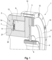
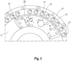
- the Figures 1 and 2 show a first embodiment using the example of an electromagnetically actuated brake 1 according to the invention.
- the brake 1 has an electromagnet 2. This has a magnet housing 7 and a coil former 8.
- the magnet housing 7 provides an annular space 9 which houses the coil former 8 in the final assembled state.
- the brake 1 also has a brake disc 3. In the final assembled state, this is arranged on a shaft not shown in the figures, for example a drive shaft of an electric motor.
- a hub 4 is used to arrange the brake disk 3 on the shaft.
- This has a tooth geometry 5 on its outside facing the brake disk 3, which in the final assembled state interacts with a counter geometry 6 on the brake disk side.
- This configuration makes it possible for the brake disc 3 to be on the Shaft is axially displaceable, but is nevertheless arranged in a rotationally fixed manner.
- the brake 1 also has an anchor plate 10. This is arranged in the axial direction between the magnet housing 7 and the brake disc 3, specifically opposite the magnet housing 7 with the interposition of compression spring elements 17 (cf. Figure 2 ) axially displaceable, but nevertheless resistant to rotation.
- a cover 11 is also provided, which is arranged on the magnet housing 7 so that it cannot rotate by means of screws 12.
- the anchor plate 10 and the brake disk 3 are arranged in the axial direction between the magnet housing 7 and the cover 11.
- the compression spring elements 17 ensure that the anchor plate 10 presses against the cover 11, namely by clamping the brake disk 3 between the anchor plate 10 and the cover 11. This creates a frictional connection, so that the brake disk 3 is between the anchor plate 10 and the lid 11 is fixed. A shaft that interacts with the brake disc 3 is also fixed.
- the coil former 8 To release the brake 1, the coil former 8 must be energized. As a result, a magnetic field is formed, whereby the anchor plate 10 moves in the axial direction against the compression spring elements 17 acting on the anchor plate 10 and is attracted by the electromagnet 2. As a result, the clamping of the brake disc 3 is released, so that it can rotate in relation to the anchor plate 10 or the cover 11, as can the shaft that is operatively connected to it.
- the brake 1 has integrated control electronics 13.
- this integration is realized in that the control electronics 13 is carried by a circuit board 14, which is housed in the annular space 9 of the magnet housing 7.
- the annular space 9 therefore not only serves to accommodate the coil former 8, but also the circuit board 14 carrying the control electronics 13.
- the circuit board 14 is accommodated in an annular gap 20, which is formed between the bobbin 8 on the one hand and a housing base 21 delimiting the annular space 9.
- the circuit board 14 together with the control electronics 13 included therein thus safely accommodated, in particular against mechanical influences, between the housing base 21 and the bobbin 8.
- control electronics 13 are cast in a casting compound. This provides additional protection for the control electronics 13, including against unwanted moisture entry.
- circuit board 14 is designed in the shape of a circular ring, specifically in the shape of a quarter of a circle in the exemplary embodiment shown.
- Figure 3 shows another embodiment using the example of a brake 1.
- a brake disc 3 is used, which is equipped with a friction lining 15 or 16 on both the anchor plate side and the cover side.
- springs 18 are provided between the magnet housing 7 and the cover 11, which, in combination with the screws 12, allow an exact gap spacing between the cover 11 and the magnet housing 7 to be set.
- a sleeve 19 covering the outer circumference of the gap between the magnet housing 7 and the cover 11 is provided.
- the brake 1 Figure 3 is designed in the manner according to the invention and has control electronics 13 which is arranged in the annular space 9 of the magnet housing 7. In the manner already described, an overall compact structure is guaranteed.
- control electronics provided according to the invention can be used not only in brakes, but also in clutches and/or clutch-brake combinations. Both spring-closing clutches, brakes or clutch-brake combinations as well as electromagnetically closing clutches, brakes or clutch-brake combinations can be provided.
Landscapes
- Engineering & Computer Science (AREA)
- General Engineering & Computer Science (AREA)
- Mechanical Engineering (AREA)
- Braking Arrangements (AREA)
Priority Applications (1)
| Application Number | Priority Date | Filing Date | Title |
|---|---|---|---|
| EP22194167.7A EP4336062B1 (fr) | 2022-09-06 | 2022-09-06 | Embrayage à commande électromagnétique, frein ou combinaison d'embrayage et de frein |
Applications Claiming Priority (1)
| Application Number | Priority Date | Filing Date | Title |
|---|---|---|---|
| EP22194167.7A EP4336062B1 (fr) | 2022-09-06 | 2022-09-06 | Embrayage à commande électromagnétique, frein ou combinaison d'embrayage et de frein |
Publications (2)
| Publication Number | Publication Date |
|---|---|
| EP4336062A1 true EP4336062A1 (fr) | 2024-03-13 |
| EP4336062B1 EP4336062B1 (fr) | 2025-11-12 |
Family
ID=83193230
Family Applications (1)
| Application Number | Title | Priority Date | Filing Date |
|---|---|---|---|
| EP22194167.7A Active EP4336062B1 (fr) | 2022-09-06 | 2022-09-06 | Embrayage à commande électromagnétique, frein ou combinaison d'embrayage et de frein |
Country Status (1)
| Country | Link |
|---|---|
| EP (1) | EP4336062B1 (fr) |
Citations (3)
| Publication number | Priority date | Publication date | Assignee | Title |
|---|---|---|---|---|
| US20060219497A1 (en) * | 2005-03-30 | 2006-10-05 | Organek Gregory J | Residual magnetic devices and methods |
| DE102008024180A1 (de) * | 2007-06-19 | 2008-12-24 | Continental Teves Ag & Co. Ohg | Kombinierte Bremsanlage, insbesondere für Kraftfahrzeuge |
| WO2019007931A1 (fr) | 2017-07-03 | 2019-01-10 | Intorq Gmbh & Co. Kg | Frein à ressort à actionnement électromagnétique et système d'entraînement |
Family Cites Families (1)
| Publication number | Priority date | Publication date | Assignee | Title |
|---|---|---|---|---|
| DE9414054U1 (de) * | 1994-08-31 | 1994-11-03 | Riepl, Gerhard, 88605 Meßkirch | Elektrischer Energiesparantrieb für Kleinfahrzeuge |
-
2022
- 2022-09-06 EP EP22194167.7A patent/EP4336062B1/fr active Active
Patent Citations (3)
| Publication number | Priority date | Publication date | Assignee | Title |
|---|---|---|---|---|
| US20060219497A1 (en) * | 2005-03-30 | 2006-10-05 | Organek Gregory J | Residual magnetic devices and methods |
| DE102008024180A1 (de) * | 2007-06-19 | 2008-12-24 | Continental Teves Ag & Co. Ohg | Kombinierte Bremsanlage, insbesondere für Kraftfahrzeuge |
| WO2019007931A1 (fr) | 2017-07-03 | 2019-01-10 | Intorq Gmbh & Co. Kg | Frein à ressort à actionnement électromagnétique et système d'entraînement |
Also Published As
| Publication number | Publication date |
|---|---|
| EP4336062B1 (fr) | 2025-11-12 |
Similar Documents
| Publication | Publication Date | Title |
|---|---|---|
| EP2005020B1 (fr) | Frein à ressort à aération électromagnétique sous forme d'un frein à quatre arêtes et à deux circuits | |
| DE102018100562A1 (de) | Motorisiertes antriebssystem, verwendung des antriebssystems zur betätigung einer tür, herstellungsverfahren für ein antriebssystem | |
| DE19652229A1 (de) | Elektromechanisch betätigbare Bremse | |
| EP2241777B1 (fr) | Couplage à bascule | |
| DE69926143T2 (de) | Hilfsantrieb mit einer elektromagnetischen kupplungseinheit | |
| EP2201260B1 (fr) | Frein constitué de quatre segments | |
| EP0111350B1 (fr) | Moteur électrique équipé d'un frein d'arrêt | |
| EP4336062A1 (fr) | Embrayage à commande électromagnétique, frein ou combinaison d'embrayage et de frein | |
| EP0568028A1 (fr) | Moteur linéaire électromagnétique | |
| EP2901037B1 (fr) | Système de frein et moteur électrique équipé d'un système de frein | |
| DE3604558A1 (de) | Magnetkoerper fuer motorbremsen | |
| DE3922794A1 (de) | Synchronmotor | |
| DE4225158A1 (de) | Elektromaschinensystem | |
| EP1070827B1 (fr) | Dispositif d'entrainement consistant en un moteur et une boíte de vitesse | |
| AT408394B (de) | Vorrichtung zum abbremsen von elektromotoren | |
| DE10153002B4 (de) | Drehsteller mit Hubmagnet, sowie Hubmagnet | |
| EP2366072B1 (fr) | Frein à actionnement électromagnétique | |
| DE102011108464A1 (de) | Bistabiler Hubmagnet für Lenkungsverriegelungen | |
| DE19946084A1 (de) | Elektromechanische Antriebseinheit | |
| DE19814078A1 (de) | Elektromagnetische Federdruckbremse | |
| DE102009051499A1 (de) | Elektromotor mit Stillstandsbremse | |
| DE202015106367U1 (de) | Elektromagnetisch lüftende Federdruckbremse in Gestalt einer mehrkreisigen Dreiecksbremse | |
| DE2225004B1 (de) | Bremseinrichtung fuer antriebsmotoren | |
| DE202023001321U1 (de) | Federdruckbremse mit optimierter Schaltzeit | |
| EP1780740B1 (fr) | Electrovanne pilote pour sectionneur hydromécanique |
Legal Events
| Date | Code | Title | Description |
|---|---|---|---|
| PUAI | Public reference made under article 153(3) epc to a published international application that has entered the european phase |
Free format text: ORIGINAL CODE: 0009012 |
|
| STAA | Information on the status of an ep patent application or granted ep patent |
Free format text: STATUS: REQUEST FOR EXAMINATION WAS MADE |
|
| 17P | Request for examination filed |
Effective date: 20230419 |
|
| AK | Designated contracting states |
Kind code of ref document: A1 Designated state(s): AL AT BE BG CH CY CZ DE DK EE ES FI FR GB GR HR HU IE IS IT LI LT LU LV MC MK MT NL NO PL PT RO RS SE SI SK SM TR |
|
| P01 | Opt-out of the competence of the unified patent court (upc) registered |
Effective date: 20240314 |
|
| STAA | Information on the status of an ep patent application or granted ep patent |
Free format text: STATUS: EXAMINATION IS IN PROGRESS |
|
| RIC1 | Information provided on ipc code assigned before grant |
Ipc: F16D 65/18 20060101AFI20240410BHEP |
|
| 17Q | First examination report despatched |
Effective date: 20240508 |
|
| GRAP | Despatch of communication of intention to grant a patent |
Free format text: ORIGINAL CODE: EPIDOSNIGR1 |
|
| STAA | Information on the status of an ep patent application or granted ep patent |
Free format text: STATUS: GRANT OF PATENT IS INTENDED |
|
| INTG | Intention to grant announced |
Effective date: 20250616 |
|
| GRAS | Grant fee paid |
Free format text: ORIGINAL CODE: EPIDOSNIGR3 |
|
| GRAA | (expected) grant |
Free format text: ORIGINAL CODE: 0009210 |
|
| STAA | Information on the status of an ep patent application or granted ep patent |
Free format text: STATUS: THE PATENT HAS BEEN GRANTED |
|
| AK | Designated contracting states |
Kind code of ref document: B1 Designated state(s): AL AT BE BG CH CY CZ DE DK EE ES FI FR GB GR HR HU IE IS IT LI LT LU LV MC MK MT NL NO PL PT RO RS SE SI SK SM TR |
|
| REG | Reference to a national code |
Ref country code: CH Ref legal event code: F10 Free format text: ST27 STATUS EVENT CODE: U-0-0-F10-F00 (AS PROVIDED BY THE NATIONAL OFFICE) Effective date: 20251112 Ref country code: GB Ref legal event code: FG4D Free format text: NOT ENGLISH |
|
| REG | Reference to a national code |
Ref country code: CH Ref legal event code: R17 Free format text: ST27 STATUS EVENT CODE: U-0-0-R10-R17 (AS PROVIDED BY THE NATIONAL OFFICE) Effective date: 20251120 |
|
| REG | Reference to a national code |
Ref country code: IE Ref legal event code: FG4D Free format text: LANGUAGE OF EP DOCUMENT: GERMAN |
|
| REG | Reference to a national code |
Ref country code: DE Ref legal event code: R096 Ref document number: 502022006103 Country of ref document: DE |
|
| REG | Reference to a national code |
Ref country code: NL Ref legal event code: MP Effective date: 20251112 |
|
| PG25 | Lapsed in a contracting state [announced via postgrant information from national office to epo] |
Ref country code: ES Free format text: LAPSE BECAUSE OF FAILURE TO SUBMIT A TRANSLATION OF THE DESCRIPTION OR TO PAY THE FEE WITHIN THE PRESCRIBED TIME-LIMIT Effective date: 20251112 |
|
| REG | Reference to a national code |
Ref country code: LT Ref legal event code: MG9D |
|
| PG25 | Lapsed in a contracting state [announced via postgrant information from national office to epo] |
Ref country code: NO Free format text: LAPSE BECAUSE OF FAILURE TO SUBMIT A TRANSLATION OF THE DESCRIPTION OR TO PAY THE FEE WITHIN THE PRESCRIBED TIME-LIMIT Effective date: 20260212 |
|
| PG25 | Lapsed in a contracting state [announced via postgrant information from national office to epo] |
Ref country code: FI Free format text: LAPSE BECAUSE OF FAILURE TO SUBMIT A TRANSLATION OF THE DESCRIPTION OR TO PAY THE FEE WITHIN THE PRESCRIBED TIME-LIMIT Effective date: 20251112 Ref country code: HR Free format text: LAPSE BECAUSE OF FAILURE TO SUBMIT A TRANSLATION OF THE DESCRIPTION OR TO PAY THE FEE WITHIN THE PRESCRIBED TIME-LIMIT Effective date: 20251112 |
|
| PG25 | Lapsed in a contracting state [announced via postgrant information from national office to epo] |
Ref country code: NL Free format text: LAPSE BECAUSE OF FAILURE TO SUBMIT A TRANSLATION OF THE DESCRIPTION OR TO PAY THE FEE WITHIN THE PRESCRIBED TIME-LIMIT Effective date: 20251112 |
|
| PG25 | Lapsed in a contracting state [announced via postgrant information from national office to epo] |
Ref country code: RS Free format text: LAPSE BECAUSE OF FAILURE TO SUBMIT A TRANSLATION OF THE DESCRIPTION OR TO PAY THE FEE WITHIN THE PRESCRIBED TIME-LIMIT Effective date: 20260212 |
|
| PG25 | Lapsed in a contracting state [announced via postgrant information from national office to epo] |
Ref country code: IS Free format text: LAPSE BECAUSE OF FAILURE TO SUBMIT A TRANSLATION OF THE DESCRIPTION OR TO PAY THE FEE WITHIN THE PRESCRIBED TIME-LIMIT Effective date: 20260312 |