EP4337867B1 - Kreiselpumpe - Google Patents
Kreiselpumpe Download PDFInfo
- Publication number
- EP4337867B1 EP4337867B1 EP22728419.7A EP22728419A EP4337867B1 EP 4337867 B1 EP4337867 B1 EP 4337867B1 EP 22728419 A EP22728419 A EP 22728419A EP 4337867 B1 EP4337867 B1 EP 4337867B1
- Authority
- EP
- European Patent Office
- Prior art keywords
- magnetic flux
- pump
- flux sensor
- turbine wheel
- rotatable disc
- Prior art date
- Legal status (The legal status is an assumption and is not a legal conclusion. Google has not performed a legal analysis and makes no representation as to the accuracy of the status listed.)
- Active
Links
Images


Classifications
-
- F—MECHANICAL ENGINEERING; LIGHTING; HEATING; WEAPONS; BLASTING
- F04—POSITIVE - DISPLACEMENT MACHINES FOR LIQUIDS; PUMPS FOR LIQUIDS OR ELASTIC FLUIDS
- F04D—NON-POSITIVE-DISPLACEMENT PUMPS
- F04D15/00—Control, e.g. regulation, of pumps, pumping installations or systems
- F04D15/0088—Testing machines
-
- F—MECHANICAL ENGINEERING; LIGHTING; HEATING; WEAPONS; BLASTING
- F04—POSITIVE - DISPLACEMENT MACHINES FOR LIQUIDS; PUMPS FOR LIQUIDS OR ELASTIC FLUIDS
- F04D—NON-POSITIVE-DISPLACEMENT PUMPS
- F04D29/00—Details, component parts, or accessories
- F04D29/40—Casings; Connections of working fluid
- F04D29/42—Casings; Connections of working fluid for radial or helico-centrifugal pumps
-
- G—PHYSICS
- G01—MEASURING; TESTING
- G01F—MEASURING VOLUME, VOLUME FLOW, MASS FLOW OR LIQUID LEVEL; METERING BY VOLUME
- G01F1/00—Measuring the volume flow or mass flow of fluid or fluent solid material wherein the fluid passes through a meter in a continuous flow
- G01F1/05—Measuring the volume flow or mass flow of fluid or fluent solid material wherein the fluid passes through a meter in a continuous flow by using mechanical effects
- G01F1/06—Measuring the volume flow or mass flow of fluid or fluent solid material wherein the fluid passes through a meter in a continuous flow by using mechanical effects using rotating vanes with tangential admission
- G01F1/065—Measuring the volume flow or mass flow of fluid or fluent solid material wherein the fluid passes through a meter in a continuous flow by using mechanical effects using rotating vanes with tangential admission with radiation as transfer means to the indicating device, e.g. light transmission
-
- G—PHYSICS
- G01—MEASURING; TESTING
- G01F—MEASURING VOLUME, VOLUME FLOW, MASS FLOW OR LIQUID LEVEL; METERING BY VOLUME
- G01F1/00—Measuring the volume flow or mass flow of fluid or fluent solid material wherein the fluid passes through a meter in a continuous flow
- G01F1/05—Measuring the volume flow or mass flow of fluid or fluent solid material wherein the fluid passes through a meter in a continuous flow by using mechanical effects
- G01F1/06—Measuring the volume flow or mass flow of fluid or fluent solid material wherein the fluid passes through a meter in a continuous flow by using mechanical effects using rotating vanes with tangential admission
- G01F1/075—Measuring the volume flow or mass flow of fluid or fluent solid material wherein the fluid passes through a meter in a continuous flow by using mechanical effects using rotating vanes with tangential admission with magnetic or electromagnetic coupling to the indicating device
Definitions
- the present invention relates to a centrifugal pump including a pump shaft, a pump casing enclosing at least one pump stage with an impeller mounted on an internal part of the pump shaft and fixed to the pump shaft for rotation with the pump shaft, a flow measuring device adapted to measure a delivery flow through the centrifugal pump by means of a turbine wheel arranged in the pump casing rotationally about the pump shaft and rotationally in relation to the pump shaft, the turbine wheel being exposed to the delivery flow through the centrifugal pump, the turbine wheel including at least one permanent magnet, the flow measuring device including at least one magnetic flux sensor, the flow measuring device being adapted to measure the delivery flow on the basis of at least a first measurement signal generated by the at least one magnetic flux sensor as a result of the rotation of the turbine wheel, and the at least one magnetic flux sensor being arranged in a sensor housing mounted in an opening formed in an outer wall of the pump casing.
- EP 3 184 823 B1 discloses a centrifugal pump including at least one pump stage.
- This pump stage includes an impeller which is mounted rotationally fixed on a pump shaft.
- the centrifugal pump is equipped with a turbine wheel which is arranged on the pump shaft, without a movement coupling to the pump shaft, in the delivery flow of the centrifugal pump.
- This turbine wheel is provided with three signal means in the form of permanent magnets and forms a transducer of a flow measuring device for measuring a delivery flow through the centrifugal pump.
- the flow measuring device further includes a sensor having a sensor housing inserted into an opening formed on an outer wall of the pump casing.
- the delivery flow determined on the basis of a turbine wheel exposed to the delivery flow through the centrifugal pump must be corrected according to the rotational speed of the impeller or impellers of the centrifugal pump.
- the rotational speed of the impeller or impellers of the centrifugal pump may be determined in a number of ways. For instance, the rotational speed may be determined on the basis of a signal received from a VFD (variable-frequency drive) for an AC (alternating current) motor driving the pump.
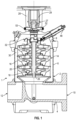
- This sensor housing 48 includes a first magnetic flux sensor 50 which on rotation of the turbine wheel 32 detects the varying magnetic field resulting from the three permanent magnets 42 of the turbine wheel 32.
- a rotatable disc 52 is mounted on the pump shaft 26 and fixed to the pump shaft for rotation with the pump shaft.
- the rotatable disc 52 includes a number of permanent magnets 53 arranged at its periphery.
- the sensor housing 48 includes a second magnetic flux sensor 51 which on rotation of the rotatable disc 52 detects the varying magnetic field resulting from the number of permanent magnets 53 of the rotatable disc 52.
- the sensor housing 48 is preferably made of corrosion resistant metal, however it could also be made of plastic. However, the sensor housing 48 should generally not be ferromagnetic, as this could disturb the magnetic fields detected by the magnetic flux sensors 50, 51.
- the flow measuring device 3 is adapted to measure, during operation of the centrifugal pump 1, the delivery flow of the pump on the basis of a first measurement signal generated by the first magnetic flux sensor 50 as a result of the rotation of the turbine wheel 32. Furthermore, according to the present invention, the flow measuring device 3 is adapted to include in the measurement of the delivery flow a second measurement signal generated by the second magnetic flux sensor 51 as a result of the rotation of the rotatable disc 52.
- a single magnetic flux sensor may be used for generating both the first measurement signal and the second measurement signal.
- Such single magnetic flux sensor may be arranged at any suitable position in the sensor housing 48.
- the first and second measurement signals need not be separated in software by demodulation, as the signals are already created separately.
- the first and second magnetic flux sensors 50, 51 may be positioned differently in the sensor housing 48, so that the position of each magnetic flux sensor may be optimised in relation to the position of the magnets 42 of the turbine wheel 32 and the magnets 53 of the rotatable disc 52, respectively. Thereby, the provided first and second measurement signals may be more reliable.
- the pump shaft 26 extends through a shaft seal 54 arranged in the outer wall of the pump casing 2.
- the external part 27 of the pump shaft 26 has a coupling end for connection with a not shown motor shaft, and the rotatable disc 52 is mounted on the external part 27 of the pump shaft 26.
- the rotatable disc 52 is clamped on a ring of the shaft seal 54.
- the rotatable disc 52 is arranged higher on the pump shaft 26, nearer to the coupling 29.
- the rotatable disc 52 is easily accessible outside the casing 2 of the pump 1 and does not take up space inside the pump casing.
- the rotatable disc 52 is directly accessible and visible so that is may be controlled that it is correctly mounted and so that is may be easily serviced. It is furthermore an advantage that the magnets 53 of the rotatable disc 52 do not have to come into contact with the fluid pumped by the centrifugal pump 1. Therefore, the choice of material for the magnets 53 is greater. For instance, neodymium-magnets may be used which are much stronger than standard permanent magnets. Neodymium-magnets should not be used in contact with drinking water.
- the rotatable disc 52 is composed by two disc halves 55, 56 clamped together and thereby clamping the pump shaft 26 in a central hole 57 through the rotatable disc 52.
- the disc halves 55, 56 are clamped together by means of screws mounted in screw holes 62.
- the permanent magnets 53 of the rotatable disc 52 may be mounted in the disc in that they are inserted in the radially outer parts of centrally open holes 63.
- the rotatable disc 52 may be constructed in any other suitable way.
- the material of the rotatable disc 52 is preferably metal, such as aluminium, but any suitable material may be used.
- the sensor housing 48 is elongated and extends through the opening 46 formed in the outer wall of the pump casing 2.
- the sensor housing 48 includes a first part 58 arranged inside the pump casing 2 and a second part 59 arranged outside the pump casing.
- the first magnetic flux sensor 50 is arranged in the first part 58 of the sensor housing 48, and the second magnetic flux sensor 51 is arranged in the second part 59 of the sensor housing 48.
- the position of the first magnetic flux sensor 50 may be optimised in that it may be positioned very close to the position of the magnets 42 of the turbine wheel 32 and inside the pump casing, so that the magnetic field of the turbine wheel does not have to be detected through the pump casing 2.
- the position of the second magnetic flux sensor 51 may be optimised in that it may be positioned outside the pump casing 2, so that the magnetic field of the magnets 53 of the rotatable disc 52 does not have to be detected through the pump casing. Thereby, the provided first and second measurement signals may be even more reliable.
- the first magnetic flux sensor 50 and the second magnetic flux sensor 51 are arranged in the sensor housing 48 with a mutual first distance d1 in a longitudinal direction L of the sensor housing 48.
- the first magnetic flux sensor 50 is arranged at a, during rotation of the turbine wheel 32, shortest second distance d2 from the at least one permanent magnet 42 of the turbine wheel 32.
- the second magnetic flux sensor 51 is arranged at a, during rotation of the rotatable disc 52, shortest third distance d3 from the at least one permanent magnet 53 of the rotatable disc 52.
- the shortest third distance d3 is at least 2 times, preferably at least 2.5 times, and most preferred at least 3 times, the shortest second distance d2.
- the mutual first distance d1 is within ⁇ 30 per cent, preferably within ⁇ 20 per cent, and most preferred within ⁇ 10 per cent of the shortest third distance d3.
- At least the second magnetic flux sensor 51 is of an omnidirectional type.
- the exact position of the rotatable disc 52 in relation to the second magnetic flux sensor 51 may not be critical. This may be an advantage, for instance because the same sensor housing design may be used for centrifugal pumps of different size, whereby a preferred position of the rotatable disc 52 on the pump shaft 26 may vary due to various constructional considerations.
- the first magnetic flux sensor 50 has a direction of maximum sensitivity, and the first magnetic flux sensor 50 is arranged with its direction of maximum sensitivity extending in the longitudinal direction L of the sensor housing 48 and in the direction of the, during rotation of the turbine wheel 32, closest position of the at least one permanent magnet 42 of the turbine wheel 32.
- the sensitivity of the first magnetic flux sensor 50 may be maximised. This may be advantageous in order to obtain a reliable first measurement signal without using special magnets providing a stronger magnetic field.
- the first and second magnetic flux sensors 50, 51 may be Hall sensors, however, coil sensors may be preferred due to better sensitivity.
Landscapes
- Engineering & Computer Science (AREA)
- Physics & Mathematics (AREA)
- Mechanical Engineering (AREA)
- General Engineering & Computer Science (AREA)
- Fluid Mechanics (AREA)
- General Physics & Mathematics (AREA)
- Electromagnetism (AREA)
- Measuring Volume Flow (AREA)
- Structures Of Non-Positive Displacement Pumps (AREA)
Claims (10)
- Kreiselpumpe (1), die eine Pumpenwelle (26), ein Pumpengehäuse (2), das mindestens eine Pumpenstufe (14) mit einem Laufrad (18), das an einem inneren Teil der Pumpenwelle (26) montiert und zur Drehung mit der Pumpenwelle an der Pumpenwelle befestigt ist, umschließt, eine Strömungsmessvorrichtung (3) beinhaltet, die dazu ausgebildet ist, einen Förderstrom durch die Kreiselpumpe (1) mittels eines Turbinenrads (32) zu messen, das im Pumpengehäuse (2) um die Pumpenwelle (26) drehend und in Bezug auf die Pumpenwelle drehend angeordnet ist, wobei das Turbinenrad (32) dem Förderstrom durch die Kreiselpumpe ausgesetzt ist, wobei das Turbinenrad (32) mindestens einen Permanentmagneten (42) beinhaltet, wobei die Strömungsmessvorrichtung (3) mindestens einen Magnetflusssensor (50, 51) beinhaltet, wobei die Strömungsmessvorrichtung (3) dazu ausgebildet ist, den Förderstrom auf Basis mindestens eines ersten Messsignals zu messen, das von dem mindestens einen Magnetflusssensor (50, 51) infolge der Drehung des Turbinenrads (32) erzeugt wird, und wobei der mindestens eine Magnetflusssensor (50, 51) in einem Sensorgehäuse (48) angeordnet ist, das in einer Öffnung (46) montiert ist, die in einer Außenwand des Pumpengehäuses (2) gebildet ist, dadurch gekennzeichnet, dass eine drehbare Scheibe (52) auf der Pumpenwelle (26) montiert und zur Drehung mit der Pumpenwelle an der Pumpenwelle befestigt ist, dass die drehbare Scheibe (52) mindestens einen Permanentmagneten (53) beinhaltet, und dass die Strömungsmessvorrichtung (3) dazu ausgebildet ist, bei der Messung des Förderstroms ein zweites Messsignal zu beinhalten, das von dem mindestens einen Magnetflusssensor (50, 51) infolge der Drehung der drehbaren Scheibe (52) erzeugt wird.
- Kreiselpumpe nach Anspruch 1, wobei sich die Pumpenwelle (26) durch eine in der Außenwand des Pumpengehäuses (2) angeordnete Wellendichtung (54) erstreckt, wobei ein äußerer Teil (27) der Pumpenwelle (26) ein Kopplungsende zur Verbindung mit einer Motorwelle aufweist und wobei die drehbare Scheibe (52) auf dem äußeren Teil (27) der Pumpenwelle (26) montiert ist.
- Kreiselpumpe nach Anspruch 2, wobei die drehbare Scheibe (52) aus zwei Scheibenhälften (55, 56) besteht, die zusammengeklemmt sind und dadurch die Pumpenwelle (26) in einem zentralen Loch (57) durch die drehbare Scheibe (52) festklemmen.
- Kreiselpumpe nach einem der vorstehenden Ansprüche, wobei der mindestens eine Magnetflusssensor (50, 51) einen ersten Magnetflusssensor (50) und einen zweiten Magnetflusssensor (51) beinhaltet, wobei der erste Magnetflusssensor (50) dazu ausgebildet ist, infolge der Drehung des Turbinenrads (32) das erste Messsignal zu erzeugen, und wobei der zweite Magnetflusssensor (51) dazu ausgebildet ist, infolge der Drehung der drehbaren Scheibe (52) das zweite Messsignal zu erzeugen.
- Kreiselpumpe nach Anspruch 4, wobei das Sensorgehäuse (48) länglich ist und sich durch die Öffnung (46) erstreckt, die in der Außenwand des Pumpengehäuses (2) gebildet ist, wobei das Sensorgehäuse (48) einen ersten Teil (58), der innerhalb des Pumpengehäuses (2) angeordnet ist, und einen zweiten Teil (59), der außerhalb des Pumpengehäuses angeordnet ist, beinhaltet, wobei der erste Magnetflusssensor (50) im ersten Teil (58) des Sensorgehäuses (48) angeordnet ist, und wobei der zweite Magnetflusssensor (51) im zweiten Teil (59) des Sensorgehäuses (48) angeordnet ist.
- Kreiselpumpe nach Anspruch 4 oder 5, wobei der erste Magnetflusssensor (50) und der zweite Magnetflusssensor (51) im Sensorgehäuse (48) mit einem gegenseitigen ersten Abstand (d1) in einer Längsrichtung des Sensorgehäuses (48) angeordnet sind, wobei der erste Magnetflusssensor (50) in einem, während Drehung des Turbinenrads (32), kürzesten zweiten Abstand (d2) von dem mindestens einen Permanentmagneten (42) des Turbinenrads (32) angeordnet ist, wobei der zweite Magnetflusssensor (51) in einem, während Drehung der drehbaren Scheibe (52), kürzesten dritten Abstand (d3) von dem mindestens einen Permanentmagneten (53) der drehbaren Scheibe (52) angeordnet ist, und wobei der kürzeste dritte Abstand (d3) mindestens das 2-Fache, vorzugsweise mindestens das 2,5-Fache und besonders bevorzugt mindestens das 3-Fache des kürzesten zweiten Abstands (d2) beträgt.
- Kreiselpumpe nach Anspruch 6, wobei der gegenseitige erste Abstand (d1) innerhalb von ±30 Prozent, vorzugsweise innerhalb von ±20 Prozent und besonders bevorzugt innerhalb von ±10 Prozent des kürzesten dritten Abstands (d3) liegt.
- Kreiselpumpe nach einem der Ansprüche 4 bis 7, wobei mindestens der zweite Magnetflusssensor (51) vom omnidirektionalen Typ ist.
- Kreiselpumpe nach einem der Ansprüche 6 bis 8, wobei der erste Magnetflusssensor (50) eine Richtung maximaler Empfindlichkeit aufweist und wobei der erste Magnetflusssensor (50) so angeordnet ist, dass sich seine Richtung maximaler Empfindlichkeit in der Längsrichtung (L) des Sensorgehäuses (48) und in der Richtung der bei Drehung des Turbinenrads (32) nächstgelegenen Position des mindestens einen Permanentmagneten (42) des Turbinenrads (32) erstreckt.
- Kreiselpumpe nach einem der vorstehenden Ansprüche, wobei die Strömungsmessvorrichtung (3) einen Prozessor beinhaltet, der dazu ausgebildet ist, einen unkorrigierten Förderstrom auf Basis des ersten Messsignals, das von dem mindestens einen Magnetflusssensor (50, 51) infolge der Drehung des Turbinenrads (32) erzeugt wird, zu berechnen, und wobei der Prozessor dazu ausgebildet ist, einen korrigierten Förderstrom durch Korrigieren des unkorrigierten Förderstroms mittels eines Korrekturfaktors auf Basis des zweiten Messsignals, das von dem mindestens einen Magnetflusssensor (50, 51) infolge der Drehung der drehbaren Scheibe (52) erzeugt wird, zu berechnen.
Applications Claiming Priority (2)
| Application Number | Priority Date | Filing Date | Title |
|---|---|---|---|
| DKPA202170233 | 2021-05-12 | ||
| PCT/EP2022/062436 WO2022238300A1 (en) | 2021-05-12 | 2022-05-09 | Centrifugal pump |
Publications (3)
| Publication Number | Publication Date |
|---|---|
| EP4337867A1 EP4337867A1 (de) | 2024-03-20 |
| EP4337867B1 true EP4337867B1 (de) | 2025-07-02 |
| EP4337867C0 EP4337867C0 (de) | 2025-07-02 |
Family
ID=81975408
Family Applications (1)
| Application Number | Title | Priority Date | Filing Date |
|---|---|---|---|
| EP22728419.7A Active EP4337867B1 (de) | 2021-05-12 | 2022-05-09 | Kreiselpumpe |
Country Status (5)
| Country | Link |
|---|---|
| US (1) | US12258970B2 (de) |
| EP (1) | EP4337867B1 (de) |
| CN (1) | CN117321309A (de) |
| ES (1) | ES3036218T3 (de) |
| WO (1) | WO2022238300A1 (de) |
Citations (1)
| Publication number | Priority date | Publication date | Assignee | Title |
|---|---|---|---|---|
| EP3184823B1 (de) * | 2015-12-21 | 2019-03-27 | Grundfos Holding A/S | Kreiselpumpe |
Family Cites Families (14)
| Publication number | Priority date | Publication date | Assignee | Title |
|---|---|---|---|---|
| US4864869A (en) * | 1988-01-04 | 1989-09-12 | General Electric Co. | Flowmeter with faraday effect optical switch readout |
| JP3689567B2 (ja) | 1998-09-29 | 2005-08-31 | 京セラ株式会社 | 遠心型血液ポンプ |
| ES1053407Y (es) | 2002-12-18 | 2003-07-16 | Bogemar Sl | Electrobomba multicelular. |
| JP2005257309A (ja) | 2004-03-09 | 2005-09-22 | Ebara Corp | タービン流量計及び流体回転機械 |
| DE602004007488T2 (de) | 2004-05-12 | 2008-03-20 | Askoll Holding S.R.L., Povolaro Di Dueville | Flüssigkeitsumwälzpumpe mit einem Synchronmotor, ausgestattet mit einer Einrichtung zum Heizen der Flüssigkeit, insbesondere für Waschmaschinen |
| EP2072829B2 (de) | 2007-12-21 | 2017-12-20 | Grundfos Management A/S | Tauchpumpe |
| JP2013099969A (ja) | 2010-03-04 | 2013-05-23 | Shinko:Kk | 流量測定機能付きポンプとそれを用いたバラスト水処理装置 |
| DE102013006142A1 (de) * | 2013-04-10 | 2014-10-16 | Fresenius Medical Care Deutschland Gmbh | Vorrichtung zum Messen eines Flüssigkeitsflusses |
| US10077777B2 (en) * | 2014-05-09 | 2018-09-18 | The Cleveland Clinic Foundation | Artificial heart system implementing suction recognition and avoidance methods |
| GB2541031B (en) * | 2015-08-07 | 2017-09-06 | Magpumps Ltd | Gear pump for pumping fluid |
| EP3563062B1 (de) * | 2016-12-30 | 2021-07-21 | Grundfos Holding A/S | Sensoranordnung und verfahren zur fehlererkennung in pumpen sowie pumpenanordnung mit solch einer sensoranordnung |
| WO2018222040A1 (en) * | 2017-05-31 | 2018-12-06 | Kinetron B.V. | Turbine flow meter, assembly, and method for measuring at least one flow characteristic |
| CN208587308U (zh) * | 2018-06-04 | 2019-03-08 | 深圳市加海科技有限公司 | 流量闭环控制的潜水泵 |
| CN109162932B (zh) * | 2018-11-07 | 2019-10-25 | 漯河市四通泵业有限公司 | 水泵内置综合检测组件及其使用方法 |
-
2022
- 2022-05-09 US US18/560,339 patent/US12258970B2/en active Active
- 2022-05-09 ES ES22728419T patent/ES3036218T3/es active Active
- 2022-05-09 WO PCT/EP2022/062436 patent/WO2022238300A1/en not_active Ceased
- 2022-05-09 EP EP22728419.7A patent/EP4337867B1/de active Active
- 2022-05-09 CN CN202280034498.6A patent/CN117321309A/zh active Pending
Patent Citations (1)
| Publication number | Priority date | Publication date | Assignee | Title |
|---|---|---|---|---|
| EP3184823B1 (de) * | 2015-12-21 | 2019-03-27 | Grundfos Holding A/S | Kreiselpumpe |
Also Published As
| Publication number | Publication date |
|---|---|
| ES3036218T3 (en) | 2025-09-16 |
| CN117321309A (zh) | 2023-12-29 |
| WO2022238300A1 (en) | 2022-11-17 |
| US20240240641A1 (en) | 2024-07-18 |
| EP4337867C0 (de) | 2025-07-02 |
| EP4337867A1 (de) | 2024-03-20 |
| US12258970B2 (en) | 2025-03-25 |
Similar Documents
| Publication | Publication Date | Title |
|---|---|---|
| US11768090B2 (en) | Fan | |
| EP1818068A2 (de) | Zentrifugalpumpenaggregat | |
| US20090162223A1 (en) | Submersible pump | |
| CN111971875A (zh) | 电动机 | |
| CN213077225U (zh) | 心室辅助泵 | |
| EP4337867B1 (de) | Kreiselpumpe | |
| US10823183B2 (en) | Centrifugal pump | |
| JP3689567B2 (ja) | 遠心型血液ポンプ | |
| CN110864008B (zh) | 泵体端盖、水泵、热水器 | |
| CN210440235U (zh) | 自动增压泵 | |
| CN210317797U (zh) | 自动增压泵 | |
| CN201210062Y (zh) | 带有导流翼片和逆转防止装置的液体流量传感器 | |
| KR100922531B1 (ko) | 역회전 검출장치를 갖는 수중펌프 | |
| JP2005257309A (ja) | タービン流量計及び流体回転機械 | |
| KR101940562B1 (ko) | 수중모터펌프 | |
| KR200346637Y1 (ko) | 유량센서 | |
| KR100400405B1 (ko) | 터빈 유량계 | |
| WO2018210483A1 (en) | A flowrate sensor | |
| JP4665543B2 (ja) | ポンプおよびそれを備えた液体供給装置 | |
| CN220708455U (zh) | 一种叶轮及流量计 | |
| TWI884410B (zh) | 電子水表及其具排壓之葉輪構造 | |
| JP5629469B2 (ja) | 送風機の回転速度検出方法及び回転速度検出装置 | |
| JPH0714822Y2 (ja) | 流量メータ | |
| CN222652294U (zh) | 一种流量传感器及电器 | |
| EP3239666A1 (de) | Elektronische ausleseanordnung für einen durchflussmesser |
Legal Events
| Date | Code | Title | Description |
|---|---|---|---|
| STAA | Information on the status of an ep patent application or granted ep patent |
Free format text: STATUS: UNKNOWN |
|
| STAA | Information on the status of an ep patent application or granted ep patent |
Free format text: STATUS: THE INTERNATIONAL PUBLICATION HAS BEEN MADE |
|
| PUAI | Public reference made under article 153(3) epc to a published international application that has entered the european phase |
Free format text: ORIGINAL CODE: 0009012 |
|
| STAA | Information on the status of an ep patent application or granted ep patent |
Free format text: STATUS: REQUEST FOR EXAMINATION WAS MADE |
|
| 17P | Request for examination filed |
Effective date: 20231110 |
|
| AK | Designated contracting states |
Kind code of ref document: A1 Designated state(s): AL AT BE BG CH CY CZ DE DK EE ES FI FR GB GR HR HU IE IS IT LI LT LU LV MC MK MT NL NO PL PT RO RS SE SI SK SM TR |
|
| DAV | Request for validation of the european patent (deleted) | ||
| DAX | Request for extension of the european patent (deleted) | ||
| GRAP | Despatch of communication of intention to grant a patent |
Free format text: ORIGINAL CODE: EPIDOSNIGR1 |
|
| STAA | Information on the status of an ep patent application or granted ep patent |
Free format text: STATUS: GRANT OF PATENT IS INTENDED |
|
| INTG | Intention to grant announced |
Effective date: 20241216 |
|
| GRAS | Grant fee paid |
Free format text: ORIGINAL CODE: EPIDOSNIGR3 |
|
| GRAA | (expected) grant |
Free format text: ORIGINAL CODE: 0009210 |
|
| STAA | Information on the status of an ep patent application or granted ep patent |
Free format text: STATUS: THE PATENT HAS BEEN GRANTED |
|
| AK | Designated contracting states |
Kind code of ref document: B1 Designated state(s): AL AT BE BG CH CY CZ DE DK EE ES FI FR GB GR HR HU IE IS IT LI LT LU LV MC MK MT NL NO PL PT RO RS SE SI SK SM TR |
|
| REG | Reference to a national code |
Ref country code: GB Ref legal event code: FG4D |
|
| REG | Reference to a national code |
Ref country code: CH Ref legal event code: EP |
|
| REG | Reference to a national code |
Ref country code: DE Ref legal event code: R096 Ref document number: 602022016919 Country of ref document: DE |
|
| REG | Reference to a national code |
Ref country code: IE Ref legal event code: FG4D |
|
| U01 | Request for unitary effect filed |
Effective date: 20250721 |
|
| U07 | Unitary effect registered |
Designated state(s): AT BE BG DE DK EE FI FR IT LT LU LV MT NL PT RO SE SI Effective date: 20250728 |
|
| REG | Reference to a national code |
Ref country code: ES Ref legal event code: FG2A Ref document number: 3036218 Country of ref document: ES Kind code of ref document: T3 Effective date: 20250916 |
|
| PG25 | Lapsed in a contracting state [announced via postgrant information from national office to epo] |
Ref country code: IS Free format text: LAPSE BECAUSE OF FAILURE TO SUBMIT A TRANSLATION OF THE DESCRIPTION OR TO PAY THE FEE WITHIN THE PRESCRIBED TIME-LIMIT Effective date: 20251102 |
|
| PG25 | Lapsed in a contracting state [announced via postgrant information from national office to epo] |
Ref country code: NO Free format text: LAPSE BECAUSE OF FAILURE TO SUBMIT A TRANSLATION OF THE DESCRIPTION OR TO PAY THE FEE WITHIN THE PRESCRIBED TIME-LIMIT Effective date: 20251002 |
|
| PG25 | Lapsed in a contracting state [announced via postgrant information from national office to epo] |
Ref country code: HR Free format text: LAPSE BECAUSE OF FAILURE TO SUBMIT A TRANSLATION OF THE DESCRIPTION OR TO PAY THE FEE WITHIN THE PRESCRIBED TIME-LIMIT Effective date: 20250702 |
|
| PG25 | Lapsed in a contracting state [announced via postgrant information from national office to epo] |
Ref country code: GR Free format text: LAPSE BECAUSE OF FAILURE TO SUBMIT A TRANSLATION OF THE DESCRIPTION OR TO PAY THE FEE WITHIN THE PRESCRIBED TIME-LIMIT Effective date: 20251003 |
|
| PG25 | Lapsed in a contracting state [announced via postgrant information from national office to epo] |
Ref country code: CZ Free format text: LAPSE BECAUSE OF FAILURE TO SUBMIT A TRANSLATION OF THE DESCRIPTION OR TO PAY THE FEE WITHIN THE PRESCRIBED TIME-LIMIT Effective date: 20250702 |
|
| PG25 | Lapsed in a contracting state [announced via postgrant information from national office to epo] |
Ref country code: PL Free format text: LAPSE BECAUSE OF FAILURE TO SUBMIT A TRANSLATION OF THE DESCRIPTION OR TO PAY THE FEE WITHIN THE PRESCRIBED TIME-LIMIT Effective date: 20250702 |
|
| PG25 | Lapsed in a contracting state [announced via postgrant information from national office to epo] |
Ref country code: RS Free format text: LAPSE BECAUSE OF FAILURE TO SUBMIT A TRANSLATION OF THE DESCRIPTION OR TO PAY THE FEE WITHIN THE PRESCRIBED TIME-LIMIT Effective date: 20251002 |
|
| PG25 | Lapsed in a contracting state [announced via postgrant information from national office to epo] |
Ref country code: SM Free format text: LAPSE BECAUSE OF FAILURE TO SUBMIT A TRANSLATION OF THE DESCRIPTION OR TO PAY THE FEE WITHIN THE PRESCRIBED TIME-LIMIT Effective date: 20250702 |