EP4342334A1 - Dossier pour chaise et chaise - Google Patents
Dossier pour chaise et chaise Download PDFInfo
- Publication number
- EP4342334A1 EP4342334A1 EP23197120.1A EP23197120A EP4342334A1 EP 4342334 A1 EP4342334 A1 EP 4342334A1 EP 23197120 A EP23197120 A EP 23197120A EP 4342334 A1 EP4342334 A1 EP 4342334A1
- Authority
- EP
- European Patent Office
- Prior art keywords
- backrest
- support
- base
- support elements
- chair
- Prior art date
- Legal status (The legal status is an assumption and is not a legal conclusion. Google has not performed a legal analysis and makes no representation as to the accuracy of the status listed.)
- Granted
Links
Images




Classifications
-
- A—HUMAN NECESSITIES
- A47—FURNITURE; DOMESTIC ARTICLES OR APPLIANCES; COFFEE MILLS; SPICE MILLS; SUCTION CLEANERS IN GENERAL
- A47C—CHAIRS; SOFAS; BEDS
- A47C7/00—Parts, details, or accessories of chairs or stools
- A47C7/36—Supports for the head or the back
- A47C7/40—Supports for the head or the back for the back
Definitions
- the present application relates to a backrest for a chair according to the preamble of claim 1. Furthermore, the present application relates to a chair according to the preamble of claim 14.
- the backrest includes a base by means of which the backrest can be connected or connected to the rest of the chair.
- This connection can in particular be made with the formation of at least one axis of rotation, so that the backrest can be pivoted about the pivot axis relative to a seat element that provides a seat for a person.
- a translational movement of the backrest relative to the rest of the chair is also possible, and in particular the base can be provided and set up to interact with the rest of the chair in a translationally movable manner.
- a translational movement in the horizontal direction (“back and forth”) may be possible.
- the base can also be connected or connected to a counterpart of the chair in a force-transmitting manner, so that forces acting on the backrest can be diverted into the rest of the chair and ultimately into a surface.
- the base is not intended for a person to lean on.
- the base can, for example, extend at an angle relative to a back element of the backrest, so that the backrest as a whole is J-shaped when viewed in a side view, with an at least essentially vertical section of the backrest being formed by the back element and the oblique section being formed by the base .
- the backrest further comprises a back element, by means of which a leaning surface is provided for the back of a person sitting on the chair. This allows the person to lean against the backrest that supports the person's back.
- the back element is connected to the base in a force-transmitting manner, so that forces acting on the back element can be diverted to the base and ultimately from the base into the rest of the chair and into the ground.
- the back element comprises a plurality of individual support elements which are designed to support different areas of the back of the person sitting on the chair.
- the support elements can, for example, interact with different areas of the back of the respective person, with the support elements each having one Provide part of the backrest surface of the back element. It is conceivable that, depending on the person's sitting position, only some or all of the support elements are used to transfer forces. This depends on how the person leans against the back element or its individual support elements.
- the chair to which the backrest can be connected or is connected can in particular be an office chair.
- the chair includes a base for placement on a surface. It also includes a seat element for providing a seat on which a person sitting on the chair can sit.
- the chair further includes a backrest which provides a leaning surface to support the person sitting on the chair. It is particularly important for office chairs that it is possible to adopt an ergonomic sitting position, with office chairs typically providing a variety of adjustment options in order to be able to be adapted to the individual stature of a respective person. This can, for example and in particular, relate to the adjustability of the backrest.
- a backrest and a chair of the type described above are already known in the prior art.
- the German disclosure document is used as an example DE 10 2018 123 731 A1 referred.
- This deals with a backrest and a chair, which can in particular be an office chair.
- the aim of the document mentioned is to provide a flexibly adjustable backrest.
- it is proposed to equip the backrest with a frame-shaped support structure which is connected to a backrest element.
- the latter has at least two different materials that have different moduli of elasticity.
- backrests especially those intended for office chairs, is extremely complex as a variety of requirements must be taken into account. This applies in particular to the supporting properties of the respective backrest, which should enable the person sitting on the chair to optimally support their back while still maintaining a high degree of freedom of movement, which encourages the person to remain "active" while sitting. In particular, it is highly recommended to regularly change your sitting position in everyday life and thereby keep your body and muscles moving.
- the backrest of such a chair actually has conflicting tasks, namely to stabilize the back and at the same time maintain flexibility that allows the person's sitting position to be changed comfortably. As a component, the backrest should ideally fade into the background for the person, so that the support and load transfer occurs as subconsciously as possible and the person is automatically encouraged to change their sitting position regularly.
- the present application is therefore based on the task of providing a backrest and a chair equipped with it, which supports healthy sitting behavior of a respective person.
- the backrest is characterized in that the support elements each have a web spaced from the base and two opposite flanges, each connected to one side of the associated web.
- a central axis of the web of a respective support element typically extends horizontally or in a horizontal plane, while central axes of the flanges each extend at least substantially vertically or in a vertical plane.
- the flanges of one respective support element face the base and are connected directly or indirectly to the base.
- the web of a respective support element is arranged at ends of the associated flanges spaced from the base. In this way, the support elements each form the shape of an inverted or upside-down U with respect to the base.
- the back element is preferably designed with a plurality of U-shaped recesses, which can in particular be slot-shaped. These recesses divide the back element into the support elements or the shape of the support elements is determined by the recesses. In other words, the back element can be designed such that the support elements are separated from one another by means of the recesses and can therefore be deformed at least substantially independently of one another.
- the support elements are arranged nested relative to one another in such a way that a further outer support element frames an adjacent, further inner support element on three sides.
- the support elements are therefore arranged in a nested manner, with first, starting from the center of the backrest surface, a first, smallest, furthest inner support element and then at least one further support element external, larger second support element framing the first support element are arranged. If more than two support elements are provided, the second support element is followed further to the outside by a further, larger third support element which frames the second support element and is optionally framed in the same way by one or more further support elements.
- At least one support element extends with its flanges into a lower end section of the back element.
- the "lower end section” refers to a section of the back element which, when the backrest is used as intended, either does not come into direct contact with the person's back or only comes into contact with a lower lumbar region. If the backrest has a lumbar support, the lower end section can be located in particular below the lumbar support.
- the flanges preferably have a length measured along their respective central axis, which is at least 50%, preferably at least 70%, more preferably at least 90%, of a length of the flange measured along a respective central axis Flanges assigned web.
- the lengths of the flanges of a support element, in particular of the innermost support element correspond at least substantially to the length of the web of the same support element.
- the support elements each have different stiffnesses in relation to the base, which is caused by the different lengths of the flanges.
- this first support element is deflected relative to the base to a lesser extent under the influence of an at least essentially horizontal force acting on its web than would be the case with a further outer support element.
- a further outer support element basically has longer flanges, whereby a lever arm of a force acting on the web of the respective support element is larger in relation to the base than with a further inner support element.
- the rigidity of the back element is therefore segmented by means of the nesting of the support elements, with the support elements being deformable at least substantially independently of one another. A deformation that acts on one of the support elements therefore has no or only a very limited direct effect on the deformation of an adjacent or other remaining support element.
- the back element can thereby support a person's back as needed and in the way that is individually required for the respective person in a respective sitting position.
- the flanges of all support elements can extend into the lower end section of the back element.
- an external support element can be subjected to a strongly disproportionate force during a lateral tilting movement of the back, while, for example, an internal support element hardly comes into contact with the person's back.
- the support elements act independently of one another, the particularly heavily loaded support element is deformed relatively strongly in the presence of the acting force and thereby avoids the movement of the person. The person therefore does not perceive the back element as an obstacle to free movement, but on the contrary is encouraged to carry out a movement without any need for the Person's unpleasantly hard counter pressure is exerted on the back by the back element.
- the backrest comprises at least three, preferably exactly three, support elements.
- This number has proven to be particularly advantageous in order to support a person's back individually as needed in different areas of the back using the support elements.
- the use of three support elements compared to an alternative embodiment that comprises more than three support elements is advantageous in that the flanges of the individual support elements can be dimensioned overall in such a way that they are mechanically suitable for transferring forces, while maintaining the usual dimensions of the back element. which experience has shown to occur as a result of a person leaning on the support elements.
- such a design of the backrest can be advantageous in which at least two flanges of adjacent support elements, which are spatially assigned to one another, are brought together to form a common hyperflange in the direction of the base.
- the said flanges of the adjacent support elements which are each assigned to the same side of the respective web, are "fused” into a common flange and are therefore not guided as separate flanges up to the base.
- the portion where the flanges are united into a common flange is referred to as a "hyperflange" in the present application.
- the hyperflange is advantageously connected directly to the base.
- the hyperflange, as well as the flanges are not connected directly to the base, but rather, for example, to an intermediate section, which then, for example, then merges directly into the base.
- the intermediate section can be located in particular in a lower third, preferably a lower quarter, of the backrest. This means that the intermediate section is designed so deep on the back element that when the backrest is used as intended, it does not act as part of the backrest surface and as such is not directly subjected to forces by the back of a person leaning on it.
- the intermediate section can therefore be formed by the lower end section.
- An embodiment is advantageous in which the flanges of at least one of the support elements, preferably several support elements, more preferably all support elements, in sections in which they are present individually (that is, in sections in which they do not form part of a hyperflange), one along their respective Have a length measured along the central axis, which has at least 50%, preferably at least 70%, more preferably 90%, of a length of the respectively assigned web measured along its central axis.
- the flanges and hyperflanges preferably extend into the lower end section of the back element.
- a cross section of the hyperflange corresponds at least substantially to a sum of the cross sections of the flanges that are brought together to form the hyperflange.
- the back element comprises a total of three support elements, the flanges of the two outer support elements being brought together from one point to form a common hyperflange and the hyperflange extending to a lower end section of the back element.
- the flanges of the innermost support element also extend into the lower end section of the back element, wherein the flanges of the innermost support element are not part of the hyperflange, but extend individually over their entire length.
- the lengths of the flanges of all support elements in which they are present individually are preferably at least 50% of the length of the respective associated web.
- the same comprises at least one stiffening strut, by means of which the flanges of at least one support element are coupled to one another in addition to the respective associated web.
- the stiffening strut is preferably connected to the ends of the flanges facing the base.
- the stiffening strut as such is not part of the support elements, so that the latter have the U-shape described above.
- at least one stiffening strut is designed such that it couples the flanges of a plurality of support elements to one another. It is also conceivable that the backrest includes a plurality of stiffening struts.
- the at least one stiffening strut is oriented at least substantially parallel to the web of the respective supporting element. This creates, so to speak, a respective Support element closed at its open end facing away from the web, so that a self-contained support structure results.
- the stiffening strut can be arranged in particular in the lower end section of the back element.
- the web of the innermost support element is arranged relative to the base in such a way that a distance of said central axis measured perpendicular to a central axis of the web of the support element from a lower end of the base is at least 50%, preferably is at least 55%, more preferably at least 60%, of a total height, which in the sense of the present application is measured from the lower end of the base to an upper end of the web of the outermost support element.
- the support elements - starting with the first, innermost support element - are assigned in their function to an upper part of the back of a respective person, in particular an upper half of the back. This area is typically where the need for back support is greatest.
- the web of at least one support element is designed to be double curved in the manner of a hyperbolic paraboloid.
- This preferably applies to the webs of all supporting elements of the backrest.
- the shape described has the advantage that the respective web has a shape adapted to the shape of the back on its surface facing the back, which forms part of the backrest surface of the back element, which is perceived as particularly comfortable.
- the web of the at least one support element is concavely curved along a central axis extending from flange to flange and convexly curved along a vertical axis oriented perpendicular to the central axis.
- the back element can have a central, preferably flat, recess which is framed on three sides by the support elements.
- the recess forms a free space that determines the shape of the innermost support element.
- the shape of the innermost support element towards the middle of the back element is determined by the recess and towards the nearest, further outer support element its shape is determined by a U-shaped recess. This is also done in the exemplary embodiment below.
- the back element comprises a lumbar support, which is preferably arranged in a lower region of the backrest surface of the back element.
- This "lower area” is characterized by the fact that it is framed by all supporting elements. So it is special advantageous if the lumbar support is formed centrally or in the middle of the back element, so that the U-shaped support elements frame the lumbar support on three sides.
- the support elements mainly interact with an upper region of a respective back as explained above, while the lumbar support is intended and set up to support a lower region of the back, in particular in the region between the first and fifth lumbar vertebrae.
- the lumbar support is particularly suitable for correcting the sitting position of a person sitting on the corresponding chair and thereby preventing discomfort in the lumbar region.
- the lumbar support can in particular be inserted into a flat recess described above, which is arranged in the lower part of the back element.
- the backrest includes a lumbar support, it is particularly advantageous if this can be mounted or mounted in a non-destructively detachable manner on the rest of the backrest, preferably on the base and/or a nearest support element. In this way, the lumbar support can be assembled or dismantled if necessary, with a lumbar support in particular being able to be retrofitted if necessary.
- such a lumbar support is particularly advantageous because its position can be changed perpendicular to the backrest surface by means of an adjusting element, so that it can be adjusted as required.
- the lumbar support can be brought into supportive engagement with the back when the person leans against the backrest.
- the lumbar support is adjustable in two directions, preferably by means of adjustment in the first direction a support surface of the lumbar support at least substantially perpendicular to the backrest surface back and forth and by means of adjustment in the second direction the support surface of the lumbar support at least substantially can be adjusted up and down parallel to the backrest surface.
- the directions in which the lumbar support can be adjusted are preferably oriented perpendicular to one another.
- the backrest is formed in one piece.
- the backrest as a whole is formed in one piece, with the back element and the base being formed as a unitary part.
- the backrest can be manufactured using an injection molding process, which gives it a one-piece shape.
- This type of design is particularly advantageous because, in the absence of transitions from one component to another component, associated weak points are avoided which in practice can, for example, lead to noise as a result of relative movements of adjacent components to one another.
- the one-piece design has the advantage that the individual elements of the backrest interact in a defined manner, while in assembled backrests the quality of the connections between the components can have an influence on the interaction. With the one-piece design, such sources of error are excluded.
- At least the back element preferably the backrest as a whole, is formed from a glass fiber reinforced plastic.
- a glass fiber reinforced plastic can be, for example, polyamide with a glass fiber content of 30%.
- Such a design is particularly advantageous in order to keep the overall mass of the backrest low, with the material having a high elasticity with a low tendency to break. The result of this is that the backrest, in particular its back element, is particularly highly deformable without causing damage and/or plastic deformation.
- the back element tapers towards the base.
- the base is preferably designed to be compact, so that it can be particularly easily connected to the rest of the chair. Accordingly, it is advantageous if the back element has a taper in the direction of an end facing the base, so that the back element is at least substantially brought together to a dimension of the base at its end facing the base.
- the backrest includes a backrest cover which is pulled over the back element in such a way that it envelops at least part of the support elements. It is conceivable that the backrest cover covers all of the support elements of the back element or only a part of the support elements.
- the backrest cover can in particular be formed from a knitted fabric. Furthermore, the backrest cover is preferably formed in one piece.
- the backrest cover can have the shape of a cover that is open on one side, so that the backrest cover can be pulled over the back element particularly easily from an upper end of the back element facing away from the base.
- the backrest cover can contribute to changing the visual appearance of the back element; What may also be technically important is the supporting effect of the backrest cover, which it can exert on the back of a person sitting on the associated chair.
- the back element has one on each of its opposite lateral edges has a cheek projecting perpendicular to the rest of the backrest surface, the cheeks together giving the back element a bowl shape.
- the backrest cover can be pulled over the back element, with the backrest cover stretched between the side, opposite cheeks of the back element and is therefore suitable for absorbing forces acting perpendicular to a surface of the backrest cover.
- the backrest cover can additionally support the supporting effect of the support elements and enable the person sitting on the respective chair to sit more comfortably.
- the protruding shape of the cheeks means that the backrest cover pulled over the cheeks first comes into contact with the backrest cover with the back of a person leaning on the back element before the back comes into contact with one or more support elements, that is to say with the actual backrest surface , comes about. This is particularly advantageous for seating comfort, since at the moment of leaning the back is initially "softly" supported by the backrest cover before the support elements are activated.
- the back element is designed in the manner described above with hyper flanges, which, for example, include the flanges of two external support elements, it can be advantageous if the cheeks are formed in the area of the hyper flanges or the hyper flanges for forming the cheeks mentioned are formed on the side edges of the back element are arched.
- the back element can comprise a total of three support elements, with the mutually assigned flanges of the two outer support elements each being combined to form a hyperflange and with the hyperflanges being arched and forming the cheeks.
- the flanges of the innermost support element are preferably not part of the hyperflange and extend individually.
- the chair is characterized in that its backrest is designed according to one of claims 1 to 13.
- the backrest provides support for the back of a person sitting on the chair without restricting the person's freedom of movement.
- the chair can be, for example, an office chair, with the base frame preferably being equipped with wheels, so that the chair is particularly easy to set up can be moved on a surface. Furthermore, it can be advantageous if the chair includes armrests on which the person sitting on the chair can rest their arms, for example their forearms. According to general regulations for the design of office chairs, the chair can provide a variety of adjustment options in order to adapt it to the individual requirements of a respective person.
- the backrest is adjustable.
- the backrest can be adjustable between a rigid and a swinging state.
- the chair can have a coupling of the seat element and the backrest, which causes the seat surface of the seat element to tilt depending on an inclination of the backrest.
- the seat element is also increasingly tilted backwards as the backrest tilts backwards.
- the inclination of the seat element is preferably significantly smaller in magnitude than the inclination of the backrest. For example, a third or a quarter of the amount of inclination of the backrest can be transferred to the seat element, so that the inclination of the latter - and therefore the seat - tilts accordingly relative to the horizontal.
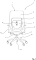
- An embodiment that is in the Figures 1 to 7 includes a chair 2, which is formed here by an office chair.
- the chair 2 includes a seat element 18, which provides a seat 19 for a person sitting on the chair 2 .
- the chair 2 includes two opposite armrests 23 arranged on the side of the seat element 18 , which are particularly good based on the Figures 1 and 2 result.
- it includes Chair 2 has a base frame 22, which in the example shown comprises a total of five sloping legs, each with a roller 30 . By means of the base frame 22, the chair 2 can be moved overall on a surface.
- the remaining elements of the chair 2 are connected to the base frame 22 to form a vertical axis of rotation 24 , so that a rotation function is provided.
- the chair 2 shown is therefore a swivel chair.
- the chair 2 also includes a backrest 1 according to the invention, which includes a back element 4 and a base 3 .
- the backrest 1 is connected to the rest of the chair 2 by means of the base 3 , as can be seen particularly well from Figure 2 results.
- the connection of the backrest 1 to the rest of the chair 2 is realized here in such a way that the backrest 1 as a whole can be pivoted about a transversely oriented pivot axis 31 relative to the chassis 22 .
- the backrest 1 is shown in a non-pivoted state.
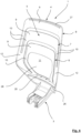
- the back element 4 comprises a total of three support elements 6, 7, 8, which can be seen particularly well based on the Figures 3 to 7 result.
- the back element 4 forms a leaning surface 5 , which is available to a person sitting on the chair 2 to lean their back against the backrest 1 .
- the backrest 1 includes, in addition to the support elements 6, 7, 8 , a lumbar support 15, by means of which the back of a respective person can be supported in the lumbar region.
- the lumbar support 15 is arranged in a center 11 of the backrest surface 5 , with the lumbar support 15 being inserted into a central recess 28 in the example shown, which is framed on three sides by the support elements 6, 7, 8 . This is explained separately below in connection with the support elements 6, 7, 8 .
- the lumbar support 15 comprises an adjusting element 25, by means of which a position of a support surface of the lumbar support 15 can be adjusted relative to the support elements 6, 7, 8 , so that the lumbar support 15 can be tailored to the individual needs of a respective person.
- the lumbar support 15 can be adjusted in two separate directions, which in the example shown are oriented perpendicular to one another.
- the support surface of the lumbar support 15 can be moved back and forth in a direction oriented at least substantially perpendicular to the backrest surface 5 and by means of an adjustment in the second direction it can be moved up and down at least substantially parallel to the backrest surface 5 become.
- the support elements 6, 7, 8 already mentioned each include a web 9 and two flanges 10.
- the flanges 10 are connected to opposite ends of the respective web 9 , so that the support elements 6, 7, 8 each have a U-shape. Since the webs 9 are each arranged at the ends of the flanges 10 facing away from the base 3 , the U-shape of each support element 6, 7, 9 is "inverted".
- the support elements 6, 7, 8 are arranged nested relative to one another in such a way that a further outer support element 7, 8 frames a further inner support element 6, 7 on three sides. This is particularly clear from the Figures 3 and 5 .
- the support elements 6, 7, 8 together form the leaning surface 5 , which is available to a person to lean on.
- the support elements 6, 7, 8 are arranged relative to the base 3 in such a way that a distance 33 between a lower end 34 of the base 3 and a central axis 13 of the web 9 of the innermost support element 6 is here approximately 65 % of a total height 32 , which extends from the lower end 34 of the base 3 to an upper end 29 of the back element 4 .
- Figure 3 This is particularly clear from: Figure 3 .
- the arrangement described means that there is a comparatively large free space between the base 3 and the web 9 of the innermost support element 6 , in which the recess 28 is present, into which the lumbar support 15 can in turn be inserted or inserted.
- the design of the support elements 6, 7, 8 in the manner described means that the sections of the backrest surface 5 provided on the webs 9 are suitable for supporting the back in the upper back area.
- the lumbar support 15, which is arranged in height relative to the base 3 below the webs 9 of the support elements 6, 7, 8 is particularly suitable for supporting the lower back area, in particular the lumbar region.
- the outermost support element 8 therefore has the lowest rigidity of the three support elements 6, 7, 8 , which leads to the support element 8 being oriented at least essentially perpendicular to the leaning surface 5 when a force is applied to its web 9 , is deflected more relative to the base 3 than would be the case with a similar load on the web 9 of the innermost support element 6 case would be.
- the support elements 6, 7, 8 therefore behave differently under a load due to the leaning of a back on the back element 4 in that a further outer support element 7, 8 deforms more strongly under the same load than a further inner support element 6, 7.
- This is particularly advantageous for seating comfort, since typically with a greater distance from the base 3 a greater deformation in the area of the backrest surface 5 is desired in order to partially avoid the leaning back and therefore not to form a "hard” stop against the back. This maintains the person's freedom of movement as the back is not hindered in its freedom of movement.
- the flanges 10 are important for the described segmentation of the leaning surface 5 , since they are each assigned separately to the associated webs 9 of the respective support element 6, 7, 8 .
- the support elements 6, 7, 8 or in particular their webs 9 are thereby deformable essentially independently of one another, so that a load on one of the webs 9 does not directly lead to a deformation of another web 9 .
- the back element 4 can individually support the back of a respective person in different areas in a segmented manner.
- the webs 9 of the back element 4 are each shaped in the manner of a hyperbolic paraboloid, as can be seen particularly well from Figure 6 results.
- the webs 9 are therefore each designed to be double curved.
- this double curvature is designed in such a way that - viewed from a front side of the back element 4 - the webs 9 each extend along their central axis 13, which extends from flange 10 to flange 10 of the respective support element 6, 7, 8 , concave and convexly curved along their vertical axis 14, which is oriented perpendicular to the central axis 13 .
- This configuration is particularly advantageous for the seating comfort that the back element 4 offers.
- the opposite hyper flanges 12 and the flanges 10 of the innermost support element 6 on the base 3 facing ends 21 of the flanges 10 are connected to one another by means of a stiffening strut 20 .
- the support elements 6, 7, 8 indirectly connected to the base 3 by means of an intermediate section, the intermediate section being formed so deep on the back element 4 that, when the backrest 1 is used as intended, it does not act as part of the backrest surface 5 and as such does not act directly from the back of one
- the leaning person is subjected to forces or comes into contact.
- the flanges 10 therefore extend into a lower end section of the back element 4.
- this is done in such a way that the flanges 10 of the innermost support element 6 extend individually (that is, not as part of a hyper flange 12) into the lower end section of the back element 4 and the flanges of the other two support elements 7, 8 are brought together above the lower end section to form hyper flanges 12 and extend as parts of the hyper flange 12 into the lower end section.
- the individual flanges 10 of the innermost support element 6 have a length measured along their central axis, which approximately corresponds to a length of the associated web 9 measured along its central axis.
- the individual flanges 10 of the central support element 7 have a length measured along their central axis, which corresponds to approximately 50% of a length of the associated web 9 measured along its central axis.
- the individual flanges 10 of the outermost support element 8 have a length measured along their central axis, which corresponds to approximately 70% of a length of the associated web 9 measured along its central axis.
- the backrest 1 is formed as a whole in one piece, being manufactured using an injection molding process. In this way, the support elements 6, 7, 8, the intermediate section and the base 3 merge directly into one another.
- the backrest 1 is made here of a glass fiber reinforced plastic.
- the support elements 6, 7, 8 are defined by recesses which are made in the back element 4 .
- the innermost support element 6 is limited or defined towards the center 11 of the leaning surface 5 by the central recess 28 and towards the middle support element 7 by a U-shaped recess.
- the U-shaped recess is slot-shaped.
- the middle support element 7 is also defined towards the outermost support element 8 by a U-shaped recess, which is also slot-shaped here.
- the outermost support element 8 forms an outer edge of the back element 4.
- the backrest 1 has a backrest cover 16, which is shown here as an example Figures 1 and 2 is recognizable.
- the backrest cover 16 is formed from a knitted fabric that is seamless.
- At the Backrest cover 16 is a cover that is open to one side and is pulled from the upper end 29 of the back element 4 over the same. In the example shown, this is done in such a way that the two outer support elements 7, 8 are enveloped by the backrest cover 16 , while the furthest inner support element 6 remains outside the backrest cover 16 .
- the backrest cover 16 leads to the appearance of the back element 4 being unified, since the segmented design of the back element 4, which results from the individual support elements 6, 7, 8 , is optically combined to form a coherent backrest surface 5 .
- the backrest cover 16 in the example shown also fulfills a technical function. This is due to the fact that the back element 4 is formed in the area of the hyper flanges 12 with cheeks 36 protruding over the rest of the backrest surface 5 or the hyper flanges 12 are arched on the side edges of the back element 4 to form the said cheeks 36 . This is particularly clear from the Figures 4 and 6 . As a result of this configuration, the back element 4 has a shell shape, as is known from typical shell seats.
- the backrest cover 16 causes the backrest cover 16 to stretch over the cheeks 36 when it is arranged on the back element 4 .
- the backrest cover 16 is suitable for absorbing forces acting perpendicularly on its surface, forming an elastic deformation, and in this way supporting the back of a person leaning on it. Since the cheeks 36 protrude somewhat beyond the rest of the backrest surface 5 , the back of the person leaning on them first comes into contact with the backrest cover 16 when leaning on it, before the support elements 6, 7, 8 are finally activated.
- the back element 4 in the example shown comprises two grooves 26, 27, which are suitable for interacting in a form-fitting manner with correspondingly designed piping of the backrest cover 16 and thereby producing a force-transmitting connection of the backrest cover 16 to the back element 4 .
Landscapes
- Chair Legs, Seat Parts, And Backrests (AREA)
Applications Claiming Priority (1)
| Application Number | Priority Date | Filing Date | Title |
|---|---|---|---|
| DE102022124131.9A DE102022124131A1 (de) | 2022-09-20 | 2022-09-20 | Rückenlehne für einen Stuhl sowie Stuhl |
Publications (3)
| Publication Number | Publication Date |
|---|---|
| EP4342334A1 true EP4342334A1 (fr) | 2024-03-27 |
| EP4342334C0 EP4342334C0 (fr) | 2025-06-04 |
| EP4342334B1 EP4342334B1 (fr) | 2025-06-04 |
Family
ID=88020839
Family Applications (1)
| Application Number | Title | Priority Date | Filing Date |
|---|---|---|---|
| EP23197120.1A Active EP4342334B1 (fr) | 2022-09-20 | 2023-09-13 | Dossier pour chaise et chaise |
Country Status (2)
| Country | Link |
|---|---|
| EP (1) | EP4342334B1 (fr) |
| DE (1) | DE102022124131A1 (fr) |
Citations (4)
| Publication number | Priority date | Publication date | Assignee | Title |
|---|---|---|---|---|
| US5997094A (en) | 1998-06-05 | 1999-12-07 | Stylex, Inc. | Stackable chair with lumbar support |
| US6409268B1 (en) | 2000-06-09 | 2002-06-25 | Stylex, Inc. | Flexible chair back |
| US7347495B2 (en) * | 2005-03-01 | 2008-03-25 | Haworth, Inc. | Chair back with lumbar and pelvic supports |
| DE102018123731A1 (de) | 2018-09-26 | 2020-03-26 | Figueroa Büro für Gestaltung GmbH | Rückenlehne sowie Sitzmöbel |
-
2022
- 2022-09-20 DE DE102022124131.9A patent/DE102022124131A1/de active Pending
-
2023
- 2023-09-13 EP EP23197120.1A patent/EP4342334B1/fr active Active
Patent Citations (4)
| Publication number | Priority date | Publication date | Assignee | Title |
|---|---|---|---|---|
| US5997094A (en) | 1998-06-05 | 1999-12-07 | Stylex, Inc. | Stackable chair with lumbar support |
| US6409268B1 (en) | 2000-06-09 | 2002-06-25 | Stylex, Inc. | Flexible chair back |
| US7347495B2 (en) * | 2005-03-01 | 2008-03-25 | Haworth, Inc. | Chair back with lumbar and pelvic supports |
| DE102018123731A1 (de) | 2018-09-26 | 2020-03-26 | Figueroa Büro für Gestaltung GmbH | Rückenlehne sowie Sitzmöbel |
Also Published As
| Publication number | Publication date |
|---|---|
| EP4342334C0 (fr) | 2025-06-04 |
| EP4342334B1 (fr) | 2025-06-04 |
| DE102022124131A1 (de) | 2024-03-21 |
Similar Documents
| Publication | Publication Date | Title |
|---|---|---|
| DE68902020T2 (de) | Kraftfahrzeugsitz. | |
| DE3879062T2 (de) | Ergonomischer stuhl. | |
| DE19646470B4 (de) | Kraftfahrzeugsitz mit einer Lehne und einem Sitz | |
| DE69132601T2 (de) | Vorrichtung für einen neigungsverstellbaren Stuhl | |
| EP1121269B1 (fr) | Siege | |
| EP2047769B1 (fr) | Siège de personnes à suspension | |
| DE69005766T2 (de) | Eine Rückenlehne für einen Sitz, insbesondere einen Kraftfahrzeugsitz. | |
| EP3409144B1 (fr) | Chaise, notamment chaise de conférence ou de bureau ainsi que procédé de fabrication d'une chaise | |
| WO2001070074A1 (fr) | Systeme d'assise et de dossier pour des sieges, notamment pour des chaises de bureau | |
| DE20302612U1 (de) | Liegestuhl | |
| AT502780A1 (de) | System zur automatischen verstellung der sitz-kontur sowie sitz, insbesondere fahrzeugsitz für automobile, flugzeuge oder dergleichen | |
| DE102014011885B4 (de) | Fahrzeugsitz mit veränderbarer Rückenlehne | |
| EP1712411B1 (fr) | Siège de véhicule à dossier deformable en forme de S | |
| EP3792101A1 (fr) | Agencement des sièges pour un moyen de transport | |
| EP2301796B1 (fr) | Siège de véhicule doté d'un dossier à contour déformable | |
| DE2822574A1 (de) | Stuhl | |
| EP3792100A1 (fr) | Agencement de sièges pour un moyen de transport | |
| DE102009043298B4 (de) | Fahrzeugsitz mit erhöhtem Sitzkomfort | |
| DE2226055A1 (de) | Sitz, insbesondere fuer kraftfahrzeuge | |
| EP4342334B1 (fr) | Dossier pour chaise et chaise | |
| DE4424096A1 (de) | Stuhl | |
| DE102004027900B4 (de) | Fahrzeugsitz | |
| EP2689692B1 (fr) | Meuble d'assise, en particulier chaise de bureau | |
| DE102004012850B4 (de) | Rückenlehne für eine Sitzvorrichtung, insbesondere für einen Drehstuhl | |
| DE202022105298U1 (de) | Rückenlehne für einen Stuhl sowie Stuhl |
Legal Events
| Date | Code | Title | Description |
|---|---|---|---|
| PUAI | Public reference made under article 153(3) epc to a published international application that has entered the european phase |
Free format text: ORIGINAL CODE: 0009012 |
|
| STAA | Information on the status of an ep patent application or granted ep patent |
Free format text: STATUS: THE APPLICATION HAS BEEN PUBLISHED |
|
| AK | Designated contracting states |
Kind code of ref document: A1 Designated state(s): AL AT BE BG CH CY CZ DE DK EE ES FI FR GB GR HR HU IE IS IT LI LT LU LV MC ME MK MT NL NO PL PT RO RS SE SI SK SM TR |
|
| STAA | Information on the status of an ep patent application or granted ep patent |
Free format text: STATUS: REQUEST FOR EXAMINATION WAS MADE |
|
| 17P | Request for examination filed |
Effective date: 20240716 |
|
| RBV | Designated contracting states (corrected) |
Designated state(s): AL AT BE BG CH CY CZ DE DK EE ES FI FR GB GR HR HU IE IS IT LI LT LU LV MC ME MK MT NL NO PL PT RO RS SE SI SK SM TR |
|
| GRAP | Despatch of communication of intention to grant a patent |
Free format text: ORIGINAL CODE: EPIDOSNIGR1 |
|
| STAA | Information on the status of an ep patent application or granted ep patent |
Free format text: STATUS: GRANT OF PATENT IS INTENDED |
|
| RIC1 | Information provided on ipc code assigned before grant |
Ipc: A47C 7/40 20060101AFI20250218BHEP |
|
| INTG | Intention to grant announced |
Effective date: 20250314 |
|
| GRAS | Grant fee paid |
Free format text: ORIGINAL CODE: EPIDOSNIGR3 |
|
| GRAA | (expected) grant |
Free format text: ORIGINAL CODE: 0009210 |
|
| STAA | Information on the status of an ep patent application or granted ep patent |
Free format text: STATUS: THE PATENT HAS BEEN GRANTED |
|
| AK | Designated contracting states |
Kind code of ref document: B1 Designated state(s): AL AT BE BG CH CY CZ DE DK EE ES FI FR GB GR HR HU IE IS IT LI LT LU LV MC ME MK MT NL NO PL PT RO RS SE SI SK SM TR |
|
| REG | Reference to a national code |
Ref country code: GB Ref legal event code: FG4D Free format text: NOT ENGLISH |
|
| REG | Reference to a national code |
Ref country code: CH Ref legal event code: EP |
|
| REG | Reference to a national code |
Ref country code: DE Ref legal event code: R096 Ref document number: 502023001088 Country of ref document: DE |
|
| REG | Reference to a national code |
Ref country code: IE Ref legal event code: FG4D Free format text: LANGUAGE OF EP DOCUMENT: GERMAN |
|
| U01 | Request for unitary effect filed |
Effective date: 20250624 |
|
| U07 | Unitary effect registered |
Designated state(s): AT BE BG DE DK EE FI FR IT LT LU LV MT NL PT RO SE SI Effective date: 20250701 |
|
| PG25 | Lapsed in a contracting state [announced via postgrant information from national office to epo] |
Ref country code: ES Free format text: LAPSE BECAUSE OF FAILURE TO SUBMIT A TRANSLATION OF THE DESCRIPTION OR TO PAY THE FEE WITHIN THE PRESCRIBED TIME-LIMIT Effective date: 20250604 |
|
| PG25 | Lapsed in a contracting state [announced via postgrant information from national office to epo] |
Ref country code: GR Free format text: LAPSE BECAUSE OF FAILURE TO SUBMIT A TRANSLATION OF THE DESCRIPTION OR TO PAY THE FEE WITHIN THE PRESCRIBED TIME-LIMIT Effective date: 20250905 Ref country code: NO Free format text: LAPSE BECAUSE OF FAILURE TO SUBMIT A TRANSLATION OF THE DESCRIPTION OR TO PAY THE FEE WITHIN THE PRESCRIBED TIME-LIMIT Effective date: 20250904 |
|
| PG25 | Lapsed in a contracting state [announced via postgrant information from national office to epo] |
Ref country code: PL Free format text: LAPSE BECAUSE OF FAILURE TO SUBMIT A TRANSLATION OF THE DESCRIPTION OR TO PAY THE FEE WITHIN THE PRESCRIBED TIME-LIMIT Effective date: 20250604 |
|
| PG25 | Lapsed in a contracting state [announced via postgrant information from national office to epo] |
Ref country code: HR Free format text: LAPSE BECAUSE OF FAILURE TO SUBMIT A TRANSLATION OF THE DESCRIPTION OR TO PAY THE FEE WITHIN THE PRESCRIBED TIME-LIMIT Effective date: 20250604 |
|
| PG25 | Lapsed in a contracting state [announced via postgrant information from national office to epo] |
Ref country code: RS Free format text: LAPSE BECAUSE OF FAILURE TO SUBMIT A TRANSLATION OF THE DESCRIPTION OR TO PAY THE FEE WITHIN THE PRESCRIBED TIME-LIMIT Effective date: 20250904 |
|
| U20 | Renewal fee for the european patent with unitary effect paid |
Year of fee payment: 3 Effective date: 20250930 |
|
| PG25 | Lapsed in a contracting state [announced via postgrant information from national office to epo] |
Ref country code: IS Free format text: LAPSE BECAUSE OF FAILURE TO SUBMIT A TRANSLATION OF THE DESCRIPTION OR TO PAY THE FEE WITHIN THE PRESCRIBED TIME-LIMIT Effective date: 20251004 |
|
| PG25 | Lapsed in a contracting state [announced via postgrant information from national office to epo] |
Ref country code: SM Free format text: LAPSE BECAUSE OF FAILURE TO SUBMIT A TRANSLATION OF THE DESCRIPTION OR TO PAY THE FEE WITHIN THE PRESCRIBED TIME-LIMIT Effective date: 20250604 |
|
| PG25 | Lapsed in a contracting state [announced via postgrant information from national office to epo] |
Ref country code: CZ Free format text: LAPSE BECAUSE OF FAILURE TO SUBMIT A TRANSLATION OF THE DESCRIPTION OR TO PAY THE FEE WITHIN THE PRESCRIBED TIME-LIMIT Effective date: 20250604 |
|
| PG25 | Lapsed in a contracting state [announced via postgrant information from national office to epo] |
Ref country code: SK Free format text: LAPSE BECAUSE OF FAILURE TO SUBMIT A TRANSLATION OF THE DESCRIPTION OR TO PAY THE FEE WITHIN THE PRESCRIBED TIME-LIMIT Effective date: 20250604 |
|
| PLBE | No opposition filed within time limit |
Free format text: ORIGINAL CODE: 0009261 |
|
| STAA | Information on the status of an ep patent application or granted ep patent |
Free format text: STATUS: NO OPPOSITION FILED WITHIN TIME LIMIT |
|
| REG | Reference to a national code |
Ref country code: CH Ref legal event code: L10 Free format text: ST27 STATUS EVENT CODE: U-0-0-L10-L00 (AS PROVIDED BY THE NATIONAL OFFICE) Effective date: 20260416 |