EP4342674B1 - Procédé de commande d'une imprimante à jet d'encre numérique - Google Patents
Procédé de commande d'une imprimante à jet d'encre numérique Download PDFInfo
- Publication number
- EP4342674B1 EP4342674B1 EP22197297.9A EP22197297A EP4342674B1 EP 4342674 B1 EP4342674 B1 EP 4342674B1 EP 22197297 A EP22197297 A EP 22197297A EP 4342674 B1 EP4342674 B1 EP 4342674B1
- Authority
- EP
- European Patent Office
- Prior art keywords
- scanning direction
- swath
- image receiving
- receiving medium
- main scanning
- Prior art date
- Legal status (The legal status is an assumption and is not a legal conclusion. Google has not performed a legal analysis and makes no representation as to the accuracy of the status listed.)
- Active
Links
Images



Classifications
-
- B—PERFORMING OPERATIONS; TRANSPORTING
- B41—PRINTING; LINING MACHINES; TYPEWRITERS; STAMPS
- B41J—TYPEWRITERS; SELECTIVE PRINTING MECHANISMS, i.e. MECHANISMS PRINTING OTHERWISE THAN FROM A FORME; CORRECTION OF TYPOGRAPHICAL ERRORS
- B41J2/00—Typewriters or selective printing mechanisms characterised by the printing or marking process for which they are designed
- B41J2/005—Typewriters or selective printing mechanisms characterised by the printing or marking process for which they are designed characterised by bringing liquid or particles selectively into contact with a printing material
- B41J2/01—Ink jet
- B41J2/135—Nozzles
- B41J2/165—Prevention or detection of nozzle clogging, e.g. cleaning, capping or moistening for nozzles
- B41J2/16517—Cleaning of print head nozzles
- B41J2/1652—Cleaning of print head nozzles by driving a fluid through the nozzles to the outside thereof, e.g. by applying pressure to the inside or vacuum at the outside of the print head
- B41J2/16526—Cleaning of print head nozzles by driving a fluid through the nozzles to the outside thereof, e.g. by applying pressure to the inside or vacuum at the outside of the print head by applying pressure only
-
- B—PERFORMING OPERATIONS; TRANSPORTING
- B41—PRINTING; LINING MACHINES; TYPEWRITERS; STAMPS
- B41J—TYPEWRITERS; SELECTIVE PRINTING MECHANISMS, i.e. MECHANISMS PRINTING OTHERWISE THAN FROM A FORME; CORRECTION OF TYPOGRAPHICAL ERRORS
- B41J2/00—Typewriters or selective printing mechanisms characterised by the printing or marking process for which they are designed
- B41J2/005—Typewriters or selective printing mechanisms characterised by the printing or marking process for which they are designed characterised by bringing liquid or particles selectively into contact with a printing material
- B41J2/01—Ink jet
- B41J2/015—Ink jet characterised by the jet generation process
- B41J2/04—Ink jet characterised by the jet generation process generating single droplets or particles on demand
- B41J2/045—Ink jet characterised by the jet generation process generating single droplets or particles on demand by pressure, e.g. electromechanical transducers
- B41J2/04501—Control methods or devices therefor, e.g. driver circuits, control circuits
- B41J2/04503—Control methods or devices therefor, e.g. driver circuits, control circuits aiming at compensating carriage speed
-
- B—PERFORMING OPERATIONS; TRANSPORTING
- B41—PRINTING; LINING MACHINES; TYPEWRITERS; STAMPS
- B41J—TYPEWRITERS; SELECTIVE PRINTING MECHANISMS, i.e. MECHANISMS PRINTING OTHERWISE THAN FROM A FORME; CORRECTION OF TYPOGRAPHICAL ERRORS
- B41J2/00—Typewriters or selective printing mechanisms characterised by the printing or marking process for which they are designed
- B41J2/005—Typewriters or selective printing mechanisms characterised by the printing or marking process for which they are designed characterised by bringing liquid or particles selectively into contact with a printing material
- B41J2/01—Ink jet
- B41J2/015—Ink jet characterised by the jet generation process
- B41J2/04—Ink jet characterised by the jet generation process generating single droplets or particles on demand
- B41J2/045—Ink jet characterised by the jet generation process generating single droplets or particles on demand by pressure, e.g. electromechanical transducers
- B41J2/04501—Control methods or devices therefor, e.g. driver circuits, control circuits
- B41J2/04526—Control methods or devices therefor, e.g. driver circuits, control circuits controlling trajectory
-
- B—PERFORMING OPERATIONS; TRANSPORTING
- B41—PRINTING; LINING MACHINES; TYPEWRITERS; STAMPS
- B41J—TYPEWRITERS; SELECTIVE PRINTING MECHANISMS, i.e. MECHANISMS PRINTING OTHERWISE THAN FROM A FORME; CORRECTION OF TYPOGRAPHICAL ERRORS
- B41J2/00—Typewriters or selective printing mechanisms characterised by the printing or marking process for which they are designed
- B41J2/005—Typewriters or selective printing mechanisms characterised by the printing or marking process for which they are designed characterised by bringing liquid or particles selectively into contact with a printing material
- B41J2/01—Ink jet
- B41J2/015—Ink jet characterised by the jet generation process
- B41J2/04—Ink jet characterised by the jet generation process generating single droplets or particles on demand
- B41J2/045—Ink jet characterised by the jet generation process generating single droplets or particles on demand by pressure, e.g. electromechanical transducers
- B41J2/04501—Control methods or devices therefor, e.g. driver circuits, control circuits
- B41J2/04586—Control methods or devices therefor, e.g. driver circuits, control circuits controlling heads of a type not covered by groups B41J2/04575 - B41J2/04585, or of an undefined type
-
- B—PERFORMING OPERATIONS; TRANSPORTING
- B41—PRINTING; LINING MACHINES; TYPEWRITERS; STAMPS
- B41J—TYPEWRITERS; SELECTIVE PRINTING MECHANISMS, i.e. MECHANISMS PRINTING OTHERWISE THAN FROM A FORME; CORRECTION OF TYPOGRAPHICAL ERRORS
- B41J2/00—Typewriters or selective printing mechanisms characterised by the printing or marking process for which they are designed
- B41J2/005—Typewriters or selective printing mechanisms characterised by the printing or marking process for which they are designed characterised by bringing liquid or particles selectively into contact with a printing material
- B41J2/01—Ink jet
- B41J2/135—Nozzles
- B41J2/165—Prevention or detection of nozzle clogging, e.g. cleaning, capping or moistening for nozzles
- B41J2/16505—Caps, spittoons or covers for cleaning or preventing drying out
- B41J2/16508—Caps, spittoons or covers for cleaning or preventing drying out connected with the printer frame
-
- B—PERFORMING OPERATIONS; TRANSPORTING
- B41—PRINTING; LINING MACHINES; TYPEWRITERS; STAMPS
- B41J—TYPEWRITERS; SELECTIVE PRINTING MECHANISMS, i.e. MECHANISMS PRINTING OTHERWISE THAN FROM A FORME; CORRECTION OF TYPOGRAPHICAL ERRORS
- B41J2/00—Typewriters or selective printing mechanisms characterised by the printing or marking process for which they are designed
- B41J2/005—Typewriters or selective printing mechanisms characterised by the printing or marking process for which they are designed characterised by bringing liquid or particles selectively into contact with a printing material
- B41J2/01—Ink jet
- B41J2/17—Ink jet characterised by ink handling
- B41J2/1721—Collecting waste ink; Collectors therefor
-
- B—PERFORMING OPERATIONS; TRANSPORTING
- B41—PRINTING; LINING MACHINES; TYPEWRITERS; STAMPS
- B41J—TYPEWRITERS; SELECTIVE PRINTING MECHANISMS, i.e. MECHANISMS PRINTING OTHERWISE THAN FROM A FORME; CORRECTION OF TYPOGRAPHICAL ERRORS
- B41J19/00—Character- or line-spacing mechanisms
- B41J19/18—Character-spacing or back-spacing mechanisms; Carriage return or release devices therefor
- B41J19/20—Positive-feed character-spacing mechanisms
- B41J19/202—Drive control means for carriage movement
-
- B—PERFORMING OPERATIONS; TRANSPORTING
- B41—PRINTING; LINING MACHINES; TYPEWRITERS; STAMPS
- B41J—TYPEWRITERS; SELECTIVE PRINTING MECHANISMS, i.e. MECHANISMS PRINTING OTHERWISE THAN FROM A FORME; CORRECTION OF TYPOGRAPHICAL ERRORS
- B41J2/00—Typewriters or selective printing mechanisms characterised by the printing or marking process for which they are designed
- B41J2/005—Typewriters or selective printing mechanisms characterised by the printing or marking process for which they are designed characterised by bringing liquid or particles selectively into contact with a printing material
- B41J2/01—Ink jet
- B41J2/135—Nozzles
- B41J2/165—Prevention or detection of nozzle clogging, e.g. cleaning, capping or moistening for nozzles
- B41J2/16517—Cleaning of print head nozzles
- B41J2002/16573—Cleaning process logic, e.g. for determining type or order of cleaning processes
-
- G—PHYSICS
- G06—COMPUTING OR CALCULATING; COUNTING
- G06K—GRAPHICAL DATA READING; PRESENTATION OF DATA; RECORD CARRIERS; HANDLING RECORD CARRIERS
- G06K15/00—Arrangements for producing a permanent visual presentation of the output data, e.g. computer output printers
- G06K15/02—Arrangements for producing a permanent visual presentation of the output data, e.g. computer output printers using printers
- G06K15/10—Arrangements for producing a permanent visual presentation of the output data, e.g. computer output printers using printers by matrix printers
- G06K15/102—Arrangements for producing a permanent visual presentation of the output data, e.g. computer output printers using printers by matrix printers using ink jet print heads
-
- G—PHYSICS
- G06—COMPUTING OR CALCULATING; COUNTING
- G06K—GRAPHICAL DATA READING; PRESENTATION OF DATA; RECORD CARRIERS; HANDLING RECORD CARRIERS
- G06K15/00—Arrangements for producing a permanent visual presentation of the output data, e.g. computer output printers
- G06K15/02—Arrangements for producing a permanent visual presentation of the output data, e.g. computer output printers using printers
- G06K15/16—Means for paper feeding or form feeding
Definitions
- the present invention relates to a method of controlling a digital inkjet printer for printing images on an image receiving medium on a printing surface
- the digital inkjet printer comprising a print controller, a print head with an array of printing elements for ejecting marking material on the image receiving medium and a maintenance tray for receiving marking material spit from at least part of the printing elements of the array, the print head mounted on a carriage that is guided on guide rails and being arranged to scan the image receiving medium in a main scanning direction in order to print swaths of marking material on the image receiving medium and to be moved relative to the image receiving medium in a sub-scanning direction normal to the main scanning direction in predetermined steps of relatively advancing the image receiving medium in the sub-scanning direction between passes of scanning the image receiving medium in the main scanning direction, wherein the maintenance tray is positioned at a side of the printing surface in the main scanning direction.
- Marking material is meant to be an ink, for example an UV curable ink.
- Image receiving medium is meant to be paper, plastic, metal, wood, transparent material, glass, cardboard, label stock, coated paper, textile or any other printable medium.
- the digital inkjet printer may hereinafter also be called an ink jet printing assembly.
- the swath time difference of consecutive swaths is kept small, which makes gloss differences unnoticeable.
- a first part of the swath time the print head is printing at least a part of the digital image.
- a second part of the swath time the print head is moving in the direction of the maintenance tray.
- a third part of the swath time the printhead reaches the maintenance tray and stays at the maintenance tray.
- the second part of the swath time is increasing from zero to a time that the maintenance tray is reached.
- the third part of the swath time is also increasing from zero to the predetermined amount of time.
- air between the print head and the maintenance tray may approximately reach a standstill. Said standstill is advantageous in order to avoid landing of ink particles outside of the maintenance tray due to moving air.
- the method comprises the step of optimizing a difference in swath times during the gradually increasing and decreasing of the swath times under a condition to minimize or obviate an appearance of print artefacts due to the change of swath times.
- the difference in swath times is selected to be maximal taking the condition into account.
- the difference in swath times during the gradually increasing and decreasing of the swath times is approximately 500 msec.
- a time difference between consecutive swaths may be chosen as large as possible, with a maximum of 500 msec.
- a swath time increase of 1200 msec is required to spit in the maintenance tray, said increase is done in two steps of 500 msec and one step of 200 msec.
- a total time of the print head to stay at the maintenance tray in step d) is approximately 2 sec. The inventor has found that by doing so, it is prevented that spit ink particles are missing the goal of the maintenance tray.
- the swaths made on the image receiving medium during the increase of the swath times in step c) are only extended on a side towards the maintenance tray and the swaths made on the image receiving medium during the decrease of the swath times in step f) are only reduced on the side from the maintenance tray.
- the trigger is issued or received each x minutes, wherein x is greater or equal to 4.
- the present invention also relates to a digital inkjet printer for printing images on an image receiving medium on a printing surface
- the digital inkjet printer comprising a print controller, a print head with an array of printing elements for ejecting marking material on the image receiving medium and a maintenance tray for receiving marking material spit from at least part of the printing elements of the array, the print head mounted on a carriage that is guided on guide rails and being arranged to scan the image receiving medium in a main scanning direction in order to print swaths of marking material on the image receiving medium and to be moved relative to the image receiving medium in a sub-scanning direction normal to the main scanning direction in predetermined steps of relatively advancing the image receiving medium in the sub-scanning direction between passes of scanning the image receiving medium in the main scanning direction, wherein the maintenance tray is positioned at a side of the printing surface in the main scanning direction, wherein the print controller is configured to control a printing a digital image in swaths with a swath time corresponding to the
- the present invention also relates to a software product comprising program code on a machine-readable medium, which program code, when loaded into a print controller of a digital inkjet printer, causes the print controller to control the digital inkjet printer in accordance with a method according to the invention.
- Fig. 1(a) shows an ink jet printing assembly 3.
- the ink jet printing assembly 3 comprises supporting means for supporting an image receiving medium 2.
- the supporting means are shown in Fig. 1(a) as a flat surface 1, but alternatively, the supporting means may be a platen, for example a rotatable drum that is rotatable around an axis.
- the supporting means may be optionally provided with suction holes for holding the image receiving medium 2 in a fixed position with respect to the supporting means.
- the ink jet printing assembly 3 comprises print heads 4a - 4e, mounted on a scanning print carriage 5.
- the scanning print carriage 5 is guided by suitable guiding means 6 to move in reciprocation in the main scanning direction X.
- Each print head 4a - 4e comprises an orifice surface 9, which orifice surface 9 is provided with at least one orifice 8, as is shown in Fig. 1(b) .
- the print heads 4a - 4e are configured to eject droplets of marking material onto the image receiving medium 2.
- the image receiving medium 2 may be a medium in web or in sheet form and may be composed of e.g. paper, cardboard, label stock, coated paper, plastic or textile. Alternatively, the image receiving medium 2 may also be an intermediate member, endless or not. Examples of endless members, which may be moved cyclically, are a belt or a drum. The image receiving medium 2 is relatively moved in the sub-scanning direction Y over the flat surface 1 along a plurality of print heads 4a - 4e provided with a fluid marking material.
- a scanning print carriage 5 carries the plurality of print heads 4a - 4e and may be moved in reciprocation in the main scanning direction X parallel to the platen 1, such as to enable scanning of the image receiving medium 2 in the main scanning direction X. Only five print heads 4a - 4e are depicted for demonstrating the invention. In practice an arbitrary number of print heads may be employed. For example, for a black-and-white printer, at least one print head 4a - 4e, usually containing black marking material is present. Alternatively, a black-and-white printer may comprise a white marking material, which is to be applied on a black image-receiving medium 2. For a full-color printer, containing multiple colors, at least one print head 4a - 4e for each of the colors, usually black, cyan, magenta, yellow and white is present.
- the carriage 5 is guided by guiding means 6.
- These guiding means 6 may be a rod as depicted in Fig. 1(a) . Although only one rod 6 is depicted in Fig. 1(a) , a plurality of rods may be used to guide the carriage 5 carrying the print heads 4.
- the rod may be driven by suitable driving means (not shown).
- the carriage 5 may be guided by other guiding means, such as an arm being able to move the carriage 5.
- Another alternative is to move the image receiving material 2 in the main scanning direction X.
- Each print head 4a - 4e comprises an orifice surface 9 having at least one orifice 8, in fluid communication with a pressure chamber containing fluid marking material provided in the print head 4a - 4e.
- a number of orifices 8 are arranged in a single linear array parallel to the sub-scanning direction Y, as is shown in Fig. 1(b) .
- the nozzles may be arranged in the main scanning direction X.
- Eight orifices 8 per print head 4a - 4e are depicted in Fig. 1(b) , however obviously in a practical embodiment several hundreds of orifices 8 may be provided per print head 4a - 4e, optionally arranged in multiple arrays.
- the respective print heads 4a - 4e are placed parallel to each other.
- the print heads 4a - 4e may be placed such that corresponding orifices 8 of the respective print heads 4a - 4e are positioned in-line in the main scanning direction X.
- a line of image dots in the main scanning direction X may be formed by selectively activating up to five orifices 8, each of them being part of a different print head 4a - 4e.
- This parallel positioning of the print heads 4a - 4e with corresponding in-line placement of the orifices 8 is advantageous to increase productivity and/or improve print quality.
- multiple print heads 4a - 4e may be placed on the print carriage adjacent to each other such that the orifices 8 of the respective print heads 4a - 4e are positioned in a staggered configuration instead of in-line. For instance, this may be done to increase the print resolution or to enlarge the effective print area, which may be addressed in a single scan in the main scanning direction X.
- the image dots are formed by ejecting droplets of marking material from the orifices 8.
- the ink jet printing assembly 3 further comprises a maintenance tray 11.
- the maintenance tray 11 is positioned at a side of the print surface 1.
- the guiding means 6 are extending towards and above the maintenance tray 11 in order to move the print heads 4a - 4e in the main scanning direction X above or even inside of the maintenance tray 11. By doing so, the print heads 4a - 4e are able to spit marking material in the maintenance tray 11.
- the ink jet assembly 3 is a roll printer and the image receiving medium 2 is moving in the sub-scanning direction Y.
- the maintenance tray 11 is at a fixed position at an end of the guiding means 6.
- the ink jet printing assembly 3 is a flatbed printer and the carriage 5 is also moving in the sub-scanning direction Y.
- the maintenance tray 11 is mounted on the guiding means 6 and moves in the sub-scanning direction Y at the same length position (in the sub-scanning direction Y) as the carriage 5 does, i.e. as the print heads 4a - 4e do.
- UV printing curing means (not shown) may be provided near the print heads 4a - 4e.
- the flat surface 1, the temperature control means, the carriage 5, the print heads 4a - 4e are controlled by a suitable print controller 10.
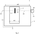
- Fig. 2 schematically shows an example of the method according to the present invention.
- An image receiving medium 2 is provided on the platen 1 and has a medium width w1 in the main scanning direction X which is smaller than the maximum media width w0 in the main scanning direction X which can be handled by the digital inkjet printer 3.
- the invention may also be applied for any image receiving medium width up to the maximum width w0.
- the print heads 4 and the maintenance tray 11 are shown along a trajectory 24.
- the trajectory 24 comprises passes from a left side turning point 25 towards a right side turning point 26 and vice versa. In the turning points 25,26 the direction of the carriage 5 with print heads 4 is inverted.
- the image receiving medium 2 is relatively moved in the sub-scanning direction Y underneath the print heads 4 and the maintenance tray 11 in such a way that a swath produced in a pass of the print heads 4 in the main direction X is at least partially overlapping with a swath produced in a next or the same pass in the main scanning direction X in an opposite direction.
- the print heads 4 are bi-directionally moving with a velocity v1 in the main scanning direction X.
- the print controller 10 may get a trigger that a spitting action needs to be performed.
- the swaths - which are originally only occupying the image receiving medium width w1 - are gradually extended towards the maintenance tray 11 in the main scanning direction X until the print heads 4 are above the maintenance tray 11. Said gradually extension goes even beyond the maximum medium width w0, since the maintenance tray 11 is positioned besides of a side of the platen 1.
- the swaths are gradually reduced to the original image receiving medium width w1.
- Fig. 3(a) - 3(b) schematically shows an embodiment of the method according to the present invention.
- a first swath A is denoted by a first rectangle 31 and a second rectangle 32.
- the first rectangle 31 represents a swath having a swath width x.
- the second rectangle 32 represents an amount of time t needed for the swath A represented by the first rectangle 31.
- a black square 33 represents the maintenance tray 11 according to the present invention.
- the maintenance tray is situated at the right side of the printing surface 1. However, a maintenance tray being situated at the left side of the printing surface 1 may also be envisioned.
- the first swath A has a swath width equal to the width w1 of the image receiving medium 2.
- a trigger is received or issued by the print controller 10 to perform a spit action.
- the print controller 10 monitors a status of each printing element 8.
- the swath time is now increased with an difference amount of time ⁇ t.
- the second swath B has now a duration which is an time amount ⁇ t greater than the duration of the first swath A.
- the difference amount of time ⁇ t is utmost 500 milliseconds.
- the pass width x of the second swath B is increased in the direction of the maintenance tray 11 represented by the black square 33.
- the swath time is further increased with the same amount of time ⁇ t, until the swath has such a width that the swath encounters 34 the maintenance tray 11.
- the print head 4 has a position 34 above the maintenance tray 11.
- the first action lasts a plurality of swaths, which plurality depends on the image receiving medium width w1 and a position of the image receiving medium 2 on the print surface 1 in the main scanning direction X.
- the preparation of the spitting is started which takes about 2 seconds in this example. Since the swath time of subsequent passes may only be increased with a time period ⁇ t, another number of passes are produced of the same swath width, but with a larger swath time 35. This effect is achieved by letting the carriage 5 wait above the maintenance tray 11 for an amount of time ⁇ t, 2 ⁇ t, 3 ⁇ t and 4 ⁇ t in the subsequent passes. It is noted that the time amount 4 ⁇ t equals the time needed for preparation of the spitting action, i.e. 2 seconds.
- the spitting 36 takes place with takes approximately a tenth of a second.
- a fourth action the swath times are reduced with the ⁇ t time period in consecutive passes by letting the carriage 5 stay a shorter time period 38 above the maintenance tray 11.
- the first action lasts 3 passes until the swath width just includes 39 the maintenance tray 11 again.
- a fifth action the swath times are further reduced with the ⁇ t time period in consecutive passes by letting the carriage 5 make passes with a smaller width so that the position 40 of the maintenance tray 11 is not reached any more.
- the fifth action lasts a plurality of swaths, in this example 4 passes, which plurality depends on the image receiving medium width w1 and a position of the image receiving medium 2 on the print surface 1 in the main scanning direction X.
- the swath time is returned to the original swath time 32 and the swath width is returned to the original swath width 31 which corresponds to the image receiving medium width w1.
- the maintenance tray 11 is composed of two parts.
- a first part is a spit tray which has a top side which intersection is slightly larger than the foot print of the print heads 4 and has a bottom side which intersection is smaller than an intersection of the top side of a second part which is positioned beneath the first part.
- the first part may have a funnel shape.
- the second part is a replaceable waste ink container in which the spit ink is gathered.
- Fig. 4 is a flow diagram of the method according to the present invention.
- the method starts in a start point A which leads to a first step S1.
- a digital image is planned or scheduled to be printed in swaths with a swath time corresponding to the width w1 of the digital image on the image receiving medium 2 in the main scanning direction X.
- a second step S2 the print controller issues or receives a trigger that a spitting action for at least part of the printing elements 8 of the print head 4 needs to be performed.
- a swath time of subsequent swaths is gradually increased until the print head reaches the maintenance tray 11.
- a fourth step S4 the print head 4 stays at the maintenance tray 11 for a predetermined amount of time for preparation of spitting in subsequent swaths. Each subsequent swath the print head 4 stays longer at the position of the maintenance tray 11 until the preparation is finished.
- a fifth step S5 the at least part of the printing elements 8 of the print head 4 spits marking material in the maintenance tray 11.
- a sixth step S6 after the spitting in the fifth step S5 the swath time of subsequent swaths are gradually decreased until the swath time is corresponding again with the width w1 of the digital image on the image receiving medium 2 in the main scanning direction X.
- the method ends in an end point B.
- plurality is defined as two or more than two.
- another is defined as at least a second or more.
- the terms including and/or having, as used herein, are defined as comprising (i.e., open language).
- coupled is defined as connected, although not necessarily directly.
Landscapes
- Ink Jet (AREA)
Claims (11)
- Procédé de commande d'une imprimante numérique à jet d'encre (3) pour l'impression d'images sur un support de réception d'images (2) sur une surface d'impression (1), l'imprimante numérique à jet d'encre (3) comprenant un contrôleur d'impression (10), une tête d'impression (4a,4b,4c,4d,4e) avec un réseau d'éléments d'impression (8) pour éjecter le matériau de marquage sur le support de réception d'image (2) et un plateau de maintenance (11) pour recevoir le matériau de marquage craché par au moins une partie des éléments d'impression (8) du réseau, la tête d'impression (4a,4b,4c,4d,4e) montée sur un chariot (5) guidé par des rails de guidage (6) et conçue pour balayer le support de réception d'image (2) dans une direction de balayage principale (X) afin d'imprimer des bandes de matériau de marquage sur le support de réception d'image (2) et pour être déplacée par rapport au support de réception d'image (2) dans une direction de balayage secondaire (Y) normale à la direction de balayage principale (X) afin d'imprimer des bandes de matériau de marquage sur le support de réception d'image (2).dans une direction de sous-balayage (Y) normale à la direction de balayage principale (X) en étapes prédéterminées d'avancement relatif du support de réception d'images (2) dans la direction de sous-balayage (Y) entre les passages de balayage du support de réception d'images (2) dans la direction de balayage principale (X), dans lequel le plateau de maintenance (11) est positionné sur un côté de la surface d'impression (1) dans la direction de balayage principale (X), la méthode comprenant les étapes suivantes :a) impression d'une image numérique en bandes avec un temps de bande correspondant à la largeur (w1) de l'image numérique sur le support de réception d'image (2) dans la direction principale de balayage (X),b) le contrôleur d'impression (10) émet ou reçoit un signal indiquant qu'une action de crachage doit être effectuée pour au moins une partie des éléments d'impression (8) de la tête d'impression (4a, 4b, 4c, 4d, 4e),c) augmenter progressivement le temps d'andainage des bandes suivantes jusqu'à ce que la tête d'impression (4a, 4b, 4c, 4d, 4e) atteigne le plateau de maintenance (11),d) la tête d'impression (4a, 4b, 4c, 4d, 4e) reste sur le plateau de maintenance (11) pendant un temps prédéterminé pour préparer les crachats sur les bandes suivantes,e) la partie au moins des éléments d'impression (8) de la tête d'impression (4a, 4b, 4c, 4d, 4e) crache un matériau de marquage dans le plateau d'entretien (11), etf) après le crachement à l'étape e), diminuer progressivement la durée d'andainage des bandes suivantes jusqu'à ce que la durée d'andainage corresponde à nouveau à la largeur (w1) de l'image numérique sur le support de réception d'image (2) dans la direction de balayage principale (X).
- Méthode selon la revendication 1, dans laquelle la méthode comprend l'étape d'optimisation d'une différence dans les temps d'andainage pendant l'augmentation et la diminution progressives des temps d'andainage dans une condition permettant de minimiser ou d'éviter l'apparition d'artefacts d'impression dus au changement des temps d'andainage.
- Procédé selon la revendication 2, dans lequel la différence de temps d'andainage est choisie pour être maximale en tenant compte de la condition.
- Procédé selon la revendication 2 ou 3, dans lequel la différence entre les temps d'andainage au cours de l'augmentation et de la diminution progressive des temps d'andainage est d'environ 500 msec.
- Procédé selon l'une quelconque des revendications précédentes, dans lequel un temps total de séjour de la tête d'impression (4a, 4b, 4c, 4d, 4e) sur le plateau de maintenance (11) à l'étape d) est d'environ 2 sec.
- Procédé selon l'une quelconque des revendications précédentes, dans lequel les andains réalisés sur le support de réception d'images (2) lors de l'augmentation des temps d'andainage à l'étape c) ne sont étendus que sur un côté en direction du plateau de maintenance (11) et les andains réalisés sur le support de réception d'images (2) lors de la diminution des temps d'andainage à l'étape f) ne sont réduits que sur le côté en provenance du plateau de maintenance (11).
- Procédé selon l'une quelconque des revendications précédentes, dans lequel le déclencheur est émis ou reçu toutes les x minutes, x étant supérieur ou égal à 4.
- Imprimante numérique à jet d'encre (3) pour imprimer des images sur un support de réception d'image (2) sur une surface d'impression (1), l'imprimante numérique à jet d'encre (3) comprenant un contrôleur d'impression (10), une tête d'impression (4a,4b,4c,4d,4e) avec un réseau d'éléments d'impression (8) pour éjecter le matériau de marquage sur le support de réception d'image (2) et un plateau de maintenance (11) pour recevoir le matériau de marquage craché par au moins une partie des éléments d'impression (8) du réseau, la tête d'impression (4a,4b,4c,4d,4e) montée sur un chariot (5) guidé par des rails de guidage (6) et conçue pour balayer le support de réception d'image (2) dans une direction de balayage principale (X) afin d'imprimer des bandes de matériau de marquage sur le support de réception d'image (2) et pour être déplacée par rapport au support de réception d'image (2) dans une direction de balayage secondaire (Y) normale à la direction de balayage principale (X) afin d'imprimer des bandes de matériau de marquage sur le support de réception d'image (2).dans une direction de sous-balayage (Y) normale à la direction de balayage principale (X) en étapes prédéterminées d'avancement relatif du support de réception d'images (2) dans la direction de sous-balayage (Y) entre les passages de balayage du support de réception d'images (2) dans la direction de balayage principale (X), dans lequel le plateau de maintenance (11) est positionné sur un côté de la surface d'impression (1) dans la direction de balayage principale (X), dans lequel le contrôleur d'impression (10) est configuré pour commander une impression d'une image numérique en bandes avec un temps de bande correspondant à la largeur (w0) de l'image numérique sur le support de réception d'image (2) dans la direction de balayage principale (X), d'émettre ou de recevoir un déclencheur indiquant qu'une action de crachage pour au moins une partie des éléments d'impression (8) de la tête d'impression (4a, 4b, 4c, 4d, 4e) doit être effectuée, d'augmenter progressivement une durée d'andainage des bandes suivantes jusqu'à ce que la tête d'impression (4a, 4b, 4c, 4d, 4e) atteigne le plateau d'entretien (11), commander la tête d'impression (4a, 4b, 4c, 4d, 4e) pour qu'elle reste sur le plateau de maintenance (11) pendant une durée prédéterminée en vue de préparer le crachage des bandes suivantes, puis pour qu'au moins une partie des éléments d'impression (8) de la tête d'impression (4a, 4b, 4c, 4d, 4e) pour cracher le matériau de marquage dans le plateau de maintenance (11) et, après le crachage, pour réduire progressivement la durée d'andainage des andains suivants jusqu'à ce que la durée d'andainage corresponde à nouveau à la largeur (w0) de l'image numérique sur le support de réception d'image (2) dans la direction de balayage principale (X).
- Imprimante numérique à jet d'encre (3) selon la revendication 8, dans laquelle l'imprimante numérique à jet d'encre (3) est une imprimante à plat et le chariot (5) est configuré pour se déplacer dans la direction de balayage principale (X) ainsi que dans la direction de sous-balayage (Y).
- Imprimante numérique à jet d'encre (3) selon la revendication 8, dans laquelle l'imprimante numérique à jet d'encre (3) est une imprimante à rouleaux et le chariot (5) est configuré pour se déplacer dans la direction principale de balayage (X) et l'imprimante numérique à jet d'encre (3) comprend des moyens de transport qui sont configurés pour déplacer le support de réception d'image (2) dans la direction de sous-balayage (Y).
- Produit logiciel comprenant un code de programme sur un support lisible par machine, lequel code de programme, lorsqu'il est chargé dans un contrôleur d'impression (10) d'une imprimante numérique à jet d'encre (3), amène le contrôleur d'impression (10) à commander l'imprimante numérique à jet d'encre (3) conformément à un procédé tel que revendiqué dans l'une quelconque des revendications 1 à 7.
Priority Applications (2)
| Application Number | Priority Date | Filing Date | Title |
|---|---|---|---|
| EP22197297.9A EP4342674B1 (fr) | 2022-09-23 | 2022-09-23 | Procédé de commande d'une imprimante à jet d'encre numérique |
| US18/368,287 US12350929B2 (en) | 2022-09-23 | 2023-09-14 | Method for controlling a digital inkjet printer |
Applications Claiming Priority (1)
| Application Number | Priority Date | Filing Date | Title |
|---|---|---|---|
| EP22197297.9A EP4342674B1 (fr) | 2022-09-23 | 2022-09-23 | Procédé de commande d'une imprimante à jet d'encre numérique |
Publications (3)
| Publication Number | Publication Date |
|---|---|
| EP4342674A1 EP4342674A1 (fr) | 2024-03-27 |
| EP4342674C0 EP4342674C0 (fr) | 2025-06-25 |
| EP4342674B1 true EP4342674B1 (fr) | 2025-06-25 |
Family
ID=83439190
Family Applications (1)
| Application Number | Title | Priority Date | Filing Date |
|---|---|---|---|
| EP22197297.9A Active EP4342674B1 (fr) | 2022-09-23 | 2022-09-23 | Procédé de commande d'une imprimante à jet d'encre numérique |
Country Status (2)
| Country | Link |
|---|---|
| US (1) | US12350929B2 (fr) |
| EP (1) | EP4342674B1 (fr) |
Family Cites Families (5)
| Publication number | Priority date | Publication date | Assignee | Title |
|---|---|---|---|---|
| JP3176184B2 (ja) * | 1993-06-30 | 2001-06-11 | キヤノン株式会社 | インクジェット記録装置及びその制御方法 |
| JP4063067B2 (ja) * | 2002-12-17 | 2008-03-19 | セイコーエプソン株式会社 | 液体噴射装置 |
| JP6784051B2 (ja) * | 2016-04-18 | 2020-11-11 | ブラザー工業株式会社 | インクジェット記録装置 |
| WO2018017067A1 (fr) * | 2016-07-19 | 2018-01-25 | Hewlett-Packard Development Company, L.P. | Système et procédé de surveillance de tête d'impression |
| JP7593150B2 (ja) * | 2021-01-29 | 2024-12-03 | ブラザー工業株式会社 | 液体吐出装置、その制御方法及びプログラム |
-
2022
- 2022-09-23 EP EP22197297.9A patent/EP4342674B1/fr active Active
-
2023
- 2023-09-14 US US18/368,287 patent/US12350929B2/en active Active
Also Published As
| Publication number | Publication date |
|---|---|
| EP4342674A1 (fr) | 2024-03-27 |
| EP4342674C0 (fr) | 2025-06-25 |
| US20240100821A1 (en) | 2024-03-28 |
| US12350929B2 (en) | 2025-07-08 |
Similar Documents
| Publication | Publication Date | Title |
|---|---|---|
| JP7292914B2 (ja) | インクジェット記録装置およびインクジェット記録方法 | |
| US8764153B2 (en) | Inkjet recording apparatus and image forming method | |
| JP5480765B2 (ja) | ライン型インクジェットプリンタの色別インク吐出量調整装置 | |
| US20080266343A1 (en) | Multipass printing method | |
| JPH08336964A (ja) | 画像を印刷するための装置 | |
| US20090237443A1 (en) | Print head servicing for a page wide array printer | |
| JP3907231B2 (ja) | カラーインクジェット印刷方法及び印刷システム | |
| JP5012429B2 (ja) | 液体吐出装置 | |
| JP2002103721A (ja) | センサにより印刷用紙の位置決めを行ってする印刷 | |
| JP5747517B2 (ja) | 記録方法及び記録装置 | |
| EP4342674B1 (fr) | Procédé de commande d'une imprimante à jet d'encre numérique | |
| JPH10138463A (ja) | インクジェット記録装置 | |
| JP5316112B2 (ja) | 画像形成装置 | |
| US8757753B2 (en) | Printing apparatus and printing method | |
| JPH07285218A (ja) | インクジェット記録方法、記録装置および情報処理システム | |
| EP2979875A1 (fr) | Appareil de formation d'image à jet d'encre et procédé de nettoyage pour appareil de formation d'image à jet d'encre | |
| JP2002240259A (ja) | 印刷方法およびインクジェット印刷装置 | |
| WO2018139272A1 (fr) | Dispositif de formation d'image, dispositif de commande, procédé de commande et programme de commande | |
| JP4818723B2 (ja) | 印刷装置 | |
| US7926906B2 (en) | Ink jet printing apparatus and ink absorber recovery method | |
| US20030179258A1 (en) | Methods and apparatus for reducing or minimizing satellite defects in fluid ejector systems | |
| JP7284871B2 (ja) | 印刷装置の較正 | |
| JP2006341461A (ja) | インクジェット記録装置 | |
| US7370928B2 (en) | Droplet discharge control method and liquid discharge apparatus | |
| JP4058429B2 (ja) | ラインドット記録装置 |
Legal Events
| Date | Code | Title | Description |
|---|---|---|---|
| PUAI | Public reference made under article 153(3) epc to a published international application that has entered the european phase |
Free format text: ORIGINAL CODE: 0009012 |
|
| STAA | Information on the status of an ep patent application or granted ep patent |
Free format text: STATUS: THE APPLICATION HAS BEEN PUBLISHED |
|
| AK | Designated contracting states |
Kind code of ref document: A1 Designated state(s): AL AT BE BG CH CY CZ DE DK EE ES FI FR GB GR HR HU IE IS IT LI LT LU LV MC MK MT NL NO PL PT RO RS SE SI SK SM TR |
|
| STAA | Information on the status of an ep patent application or granted ep patent |
Free format text: STATUS: REQUEST FOR EXAMINATION WAS MADE |
|
| 17P | Request for examination filed |
Effective date: 20240927 |
|
| RBV | Designated contracting states (corrected) |
Designated state(s): AL AT BE BG CH CY CZ DE DK EE ES FI FR GB GR HR HU IE IS IT LI LT LU LV MC MK MT NL NO PL PT RO RS SE SI SK SM TR |
|
| GRAP | Despatch of communication of intention to grant a patent |
Free format text: ORIGINAL CODE: EPIDOSNIGR1 |
|
| STAA | Information on the status of an ep patent application or granted ep patent |
Free format text: STATUS: GRANT OF PATENT IS INTENDED |
|
| RIC1 | Information provided on ipc code assigned before grant |
Ipc: B41J 19/20 20060101ALI20250123BHEP Ipc: B41J 2/165 20060101AFI20250123BHEP |
|
| INTG | Intention to grant announced |
Effective date: 20250131 |
|
| GRAS | Grant fee paid |
Free format text: ORIGINAL CODE: EPIDOSNIGR3 |
|
| GRAA | (expected) grant |
Free format text: ORIGINAL CODE: 0009210 |
|
| STAA | Information on the status of an ep patent application or granted ep patent |
Free format text: STATUS: THE PATENT HAS BEEN GRANTED |
|
| AK | Designated contracting states |
Kind code of ref document: B1 Designated state(s): AL AT BE BG CH CY CZ DE DK EE ES FI FR GB GR HR HU IE IS IT LI LT LU LV MC MK MT NL NO PL PT RO RS SE SI SK SM TR |
|
| REG | Reference to a national code |
Ref country code: GB Ref legal event code: FG4D |
|
| REG | Reference to a national code |
Ref country code: CH Ref legal event code: EP |
|
| REG | Reference to a national code |
Ref country code: DE Ref legal event code: R096 Ref document number: 602022016366 Country of ref document: DE |
|
| REG | Reference to a national code |
Ref country code: CH Ref legal event code: EP |
|
| REG | Reference to a national code |
Ref country code: IE Ref legal event code: FG4D |
|
| U01 | Request for unitary effect filed |
Effective date: 20250711 |
|
| U07 | Unitary effect registered |
Designated state(s): AT BE BG DE DK EE FI FR IT LT LU LV MT NL PT RO SE SI Effective date: 20250717 |
|
| PG25 | Lapsed in a contracting state [announced via postgrant information from national office to epo] |
Ref country code: NO Free format text: LAPSE BECAUSE OF FAILURE TO SUBMIT A TRANSLATION OF THE DESCRIPTION OR TO PAY THE FEE WITHIN THE PRESCRIBED TIME-LIMIT Effective date: 20250925 Ref country code: GR Free format text: LAPSE BECAUSE OF FAILURE TO SUBMIT A TRANSLATION OF THE DESCRIPTION OR TO PAY THE FEE WITHIN THE PRESCRIBED TIME-LIMIT Effective date: 20250926 |
|
| PG25 | Lapsed in a contracting state [announced via postgrant information from national office to epo] |
Ref country code: HR Free format text: LAPSE BECAUSE OF FAILURE TO SUBMIT A TRANSLATION OF THE DESCRIPTION OR TO PAY THE FEE WITHIN THE PRESCRIBED TIME-LIMIT Effective date: 20250625 |
|
| PG25 | Lapsed in a contracting state [announced via postgrant information from national office to epo] |
Ref country code: RS Free format text: LAPSE BECAUSE OF FAILURE TO SUBMIT A TRANSLATION OF THE DESCRIPTION OR TO PAY THE FEE WITHIN THE PRESCRIBED TIME-LIMIT Effective date: 20250925 |
|
| U20 | Renewal fee for the european patent with unitary effect paid |
Year of fee payment: 4 Effective date: 20251017 |
|
| PG25 | Lapsed in a contracting state [announced via postgrant information from national office to epo] |
Ref country code: IS Free format text: LAPSE BECAUSE OF FAILURE TO SUBMIT A TRANSLATION OF THE DESCRIPTION OR TO PAY THE FEE WITHIN THE PRESCRIBED TIME-LIMIT Effective date: 20251025 |
|
| PG25 | Lapsed in a contracting state [announced via postgrant information from national office to epo] |
Ref country code: SM Free format text: LAPSE BECAUSE OF FAILURE TO SUBMIT A TRANSLATION OF THE DESCRIPTION OR TO PAY THE FEE WITHIN THE PRESCRIBED TIME-LIMIT Effective date: 20250625 |
|
| PG25 | Lapsed in a contracting state [announced via postgrant information from national office to epo] |
Ref country code: CZ Free format text: LAPSE BECAUSE OF FAILURE TO SUBMIT A TRANSLATION OF THE DESCRIPTION OR TO PAY THE FEE WITHIN THE PRESCRIBED TIME-LIMIT Effective date: 20250625 |
|
| PG25 | Lapsed in a contracting state [announced via postgrant information from national office to epo] |
Ref country code: PL Free format text: LAPSE BECAUSE OF FAILURE TO SUBMIT A TRANSLATION OF THE DESCRIPTION OR TO PAY THE FEE WITHIN THE PRESCRIBED TIME-LIMIT Effective date: 20250625 |
|
| PG25 | Lapsed in a contracting state [announced via postgrant information from national office to epo] |
Ref country code: SK Free format text: LAPSE BECAUSE OF FAILURE TO SUBMIT A TRANSLATION OF THE DESCRIPTION OR TO PAY THE FEE WITHIN THE PRESCRIBED TIME-LIMIT Effective date: 20250625 |
|
| PG25 | Lapsed in a contracting state [announced via postgrant information from national office to epo] |
Ref country code: ES Free format text: LAPSE BECAUSE OF FAILURE TO SUBMIT A TRANSLATION OF THE DESCRIPTION OR TO PAY THE FEE WITHIN THE PRESCRIBED TIME-LIMIT Effective date: 20250625 |
|
| PLBE | No opposition filed within time limit |
Free format text: ORIGINAL CODE: 0009261 |
|
| STAA | Information on the status of an ep patent application or granted ep patent |
Free format text: STATUS: NO OPPOSITION FILED WITHIN TIME LIMIT |