EP4342806B1 - Système d'échange de lattes dans des machines de thermosoudage ayant des cellules ou des cavités alvéolaires - Google Patents
Système d'échange de lattes dans des machines de thermosoudage ayant des cellules ou des cavités alvéolaires Download PDFInfo
- Publication number
- EP4342806B1 EP4342806B1 EP23197964.2A EP23197964A EP4342806B1 EP 4342806 B1 EP4342806 B1 EP 4342806B1 EP 23197964 A EP23197964 A EP 23197964A EP 4342806 B1 EP4342806 B1 EP 4342806B1
- Authority
- EP
- European Patent Office
- Prior art keywords
- slat
- thermo
- slat part
- removable
- cells
- Prior art date
- Legal status (The legal status is an assumption and is not a legal conclusion. Google has not performed a legal analysis and makes no representation as to the accuracy of the status listed.)
- Active
Links
Images


Classifications
-
- B—PERFORMING OPERATIONS; TRANSPORTING
- B65—CONVEYING; PACKING; STORING; HANDLING THIN OR FILAMENTARY MATERIAL
- B65B—MACHINES, APPARATUS OR DEVICES FOR, OR METHODS OF, PACKAGING ARTICLES OR MATERIALS; UNPACKING
- B65B51/00—Devices for, or methods of, sealing or securing package folds or closures; Devices for gathering or twisting wrappers, or necks of bags
- B65B51/10—Applying or generating heat or pressure or combinations thereof
- B65B51/14—Applying or generating heat or pressure or combinations thereof by reciprocating or oscillating members
-
- B—PERFORMING OPERATIONS; TRANSPORTING
- B29—WORKING OF PLASTICS; WORKING OF SUBSTANCES IN A PLASTIC STATE IN GENERAL
- B29C—SHAPING OR JOINING OF PLASTICS; SHAPING OF MATERIAL IN A PLASTIC STATE, NOT OTHERWISE PROVIDED FOR; AFTER-TREATMENT OF THE SHAPED PRODUCTS, e.g. REPAIRING
- B29C65/00—Joining or sealing of preformed parts, e.g. welding of plastics materials; Apparatus therefor
- B29C65/02—Joining or sealing of preformed parts, e.g. welding of plastics materials; Apparatus therefor by heating, with or without pressure
-
- B—PERFORMING OPERATIONS; TRANSPORTING
- B29—WORKING OF PLASTICS; WORKING OF SUBSTANCES IN A PLASTIC STATE IN GENERAL
- B29C—SHAPING OR JOINING OF PLASTICS; SHAPING OF MATERIAL IN A PLASTIC STATE, NOT OTHERWISE PROVIDED FOR; AFTER-TREATMENT OF THE SHAPED PRODUCTS, e.g. REPAIRING
- B29C65/00—Joining or sealing of preformed parts, e.g. welding of plastics materials; Apparatus therefor
- B29C65/78—Means for handling the parts to be joined, e.g. for making containers or hollow articles, e.g. means for handling sheets, plates, web-like materials, tubular articles, hollow articles or elements to be joined therewith; Means for discharging the joined articles from the joining apparatus
- B29C65/7858—Means for handling the parts to be joined, e.g. for making containers or hollow articles, e.g. means for handling sheets, plates, web-like materials, tubular articles, hollow articles or elements to be joined therewith; Means for discharging the joined articles from the joining apparatus characterised by the feeding movement of the parts to be joined
- B29C65/7861—In-line machines, i.e. feeding, joining and discharging are in one production line
- B29C65/7867—In-line machines, i.e. feeding, joining and discharging are in one production line using carriers, provided with holding means, said carriers moving in a closed path
-
- B—PERFORMING OPERATIONS; TRANSPORTING
- B29—WORKING OF PLASTICS; WORKING OF SUBSTANCES IN A PLASTIC STATE IN GENERAL
- B29C—SHAPING OR JOINING OF PLASTICS; SHAPING OF MATERIAL IN A PLASTIC STATE, NOT OTHERWISE PROVIDED FOR; AFTER-TREATMENT OF THE SHAPED PRODUCTS, e.g. REPAIRING
- B29C66/00—General aspects of processes or apparatus for joining preformed parts
- B29C66/01—General aspects dealing with the joint area or with the area to be joined
- B29C66/05—Particular design of joint configurations
- B29C66/10—Particular design of joint configurations particular design of the joint cross-sections
- B29C66/11—Joint cross-sections comprising a single joint-segment, i.e. one of the parts to be joined comprising a single joint-segment in the joint cross-section
- B29C66/112—Single lapped joints
- B29C66/1122—Single lap to lap joints, i.e. overlap joints
-
- B—PERFORMING OPERATIONS; TRANSPORTING
- B29—WORKING OF PLASTICS; WORKING OF SUBSTANCES IN A PLASTIC STATE IN GENERAL
- B29C—SHAPING OR JOINING OF PLASTICS; SHAPING OF MATERIAL IN A PLASTIC STATE, NOT OTHERWISE PROVIDED FOR; AFTER-TREATMENT OF THE SHAPED PRODUCTS, e.g. REPAIRING
- B29C66/00—General aspects of processes or apparatus for joining preformed parts
- B29C66/01—General aspects dealing with the joint area or with the area to be joined
- B29C66/05—Particular design of joint configurations
- B29C66/20—Particular design of joint configurations particular design of the joint lines, e.g. of the weld lines
- B29C66/24—Particular design of joint configurations particular design of the joint lines, e.g. of the weld lines said joint lines being closed or non-straight
- B29C66/246—Particular design of joint configurations particular design of the joint lines, e.g. of the weld lines said joint lines being closed or non-straight said joint lines forming figures, e.g. animals, flowers, hearts
-
- B—PERFORMING OPERATIONS; TRANSPORTING
- B29—WORKING OF PLASTICS; WORKING OF SUBSTANCES IN A PLASTIC STATE IN GENERAL
- B29C—SHAPING OR JOINING OF PLASTICS; SHAPING OF MATERIAL IN A PLASTIC STATE, NOT OTHERWISE PROVIDED FOR; AFTER-TREATMENT OF THE SHAPED PRODUCTS, e.g. REPAIRING
- B29C66/00—General aspects of processes or apparatus for joining preformed parts
- B29C66/50—General aspects of joining tubular articles; General aspects of joining long products, i.e. bars or profiled elements; General aspects of joining single elements to tubular articles, hollow articles or bars; General aspects of joining several hollow-preforms to form hollow or tubular articles
- B29C66/51—Joining tubular articles, profiled elements or bars; Joining single elements to tubular articles, hollow articles or bars; Joining several hollow-preforms to form hollow or tubular articles
- B29C66/53—Joining single elements to tubular articles, hollow articles or bars
- B29C66/534—Joining single elements to open ends of tubular or hollow articles or to the ends of bars
- B29C66/5346—Joining single elements to open ends of tubular or hollow articles or to the ends of bars said single elements being substantially flat
- B29C66/53461—Joining single elements to open ends of tubular or hollow articles or to the ends of bars said single elements being substantially flat joining substantially flat covers and/or substantially flat bottoms to open ends of container bodies
-
- B—PERFORMING OPERATIONS; TRANSPORTING
- B29—WORKING OF PLASTICS; WORKING OF SUBSTANCES IN A PLASTIC STATE IN GENERAL
- B29C—SHAPING OR JOINING OF PLASTICS; SHAPING OF MATERIAL IN A PLASTIC STATE, NOT OTHERWISE PROVIDED FOR; AFTER-TREATMENT OF THE SHAPED PRODUCTS, e.g. REPAIRING
- B29C66/00—General aspects of processes or apparatus for joining preformed parts
- B29C66/80—General aspects of machine operations or constructions and parts thereof
- B29C66/81—General aspects of the pressing elements, i.e. the elements applying pressure on the parts to be joined in the area to be joined, e.g. the welding jaws or clamps
- B29C66/816—General aspects of the pressing elements, i.e. the elements applying pressure on the parts to be joined in the area to be joined, e.g. the welding jaws or clamps characterised by the mounting of the pressing elements, e.g. of the welding jaws or clamps
- B29C66/8167—Quick change joining tools or surfaces
-
- B—PERFORMING OPERATIONS; TRANSPORTING
- B29—WORKING OF PLASTICS; WORKING OF SUBSTANCES IN A PLASTIC STATE IN GENERAL
- B29C—SHAPING OR JOINING OF PLASTICS; SHAPING OF MATERIAL IN A PLASTIC STATE, NOT OTHERWISE PROVIDED FOR; AFTER-TREATMENT OF THE SHAPED PRODUCTS, e.g. REPAIRING
- B29C66/00—General aspects of processes or apparatus for joining preformed parts
- B29C66/80—General aspects of machine operations or constructions and parts thereof
- B29C66/84—Specific machine types or machines suitable for specific applications
- B29C66/841—Machines or tools adaptable for making articles of different dimensions or shapes or for making joints of different dimensions
-
- B—PERFORMING OPERATIONS; TRANSPORTING
- B29—WORKING OF PLASTICS; WORKING OF SUBSTANCES IN A PLASTIC STATE IN GENERAL
- B29C—SHAPING OR JOINING OF PLASTICS; SHAPING OF MATERIAL IN A PLASTIC STATE, NOT OTHERWISE PROVIDED FOR; AFTER-TREATMENT OF THE SHAPED PRODUCTS, e.g. REPAIRING
- B29C66/00—General aspects of processes or apparatus for joining preformed parts
- B29C66/80—General aspects of machine operations or constructions and parts thereof
- B29C66/84—Specific machine types or machines suitable for specific applications
- B29C66/843—Machines for making separate joints at the same time in different planes; Machines for making separate joints at the same time mounted in parallel or in series
- B29C66/8432—Machines for making separate joints at the same time mounted in parallel or in series
-
- B—PERFORMING OPERATIONS; TRANSPORTING
- B29—WORKING OF PLASTICS; WORKING OF SUBSTANCES IN A PLASTIC STATE IN GENERAL
- B29C—SHAPING OR JOINING OF PLASTICS; SHAPING OF MATERIAL IN A PLASTIC STATE, NOT OTHERWISE PROVIDED FOR; AFTER-TREATMENT OF THE SHAPED PRODUCTS, e.g. REPAIRING
- B29C66/00—General aspects of processes or apparatus for joining preformed parts
- B29C66/80—General aspects of machine operations or constructions and parts thereof
- B29C66/84—Specific machine types or machines suitable for specific applications
- B29C66/849—Packaging machines
-
- B—PERFORMING OPERATIONS; TRANSPORTING
- B29—WORKING OF PLASTICS; WORKING OF SUBSTANCES IN A PLASTIC STATE IN GENERAL
- B29C—SHAPING OR JOINING OF PLASTICS; SHAPING OF MATERIAL IN A PLASTIC STATE, NOT OTHERWISE PROVIDED FOR; AFTER-TREATMENT OF THE SHAPED PRODUCTS, e.g. REPAIRING
- B29C66/00—General aspects of processes or apparatus for joining preformed parts
- B29C66/80—General aspects of machine operations or constructions and parts thereof
- B29C66/84—Specific machine types or machines suitable for specific applications
- B29C66/863—Robotised, e.g. mounted on a robot arm
-
- B—PERFORMING OPERATIONS; TRANSPORTING
- B29—WORKING OF PLASTICS; WORKING OF SUBSTANCES IN A PLASTIC STATE IN GENERAL
- B29C—SHAPING OR JOINING OF PLASTICS; SHAPING OF MATERIAL IN A PLASTIC STATE, NOT OTHERWISE PROVIDED FOR; AFTER-TREATMENT OF THE SHAPED PRODUCTS, e.g. REPAIRING
- B29C66/00—General aspects of processes or apparatus for joining preformed parts
- B29C66/80—General aspects of machine operations or constructions and parts thereof
- B29C66/87—Auxiliary operations or devices
- B29C66/876—Maintenance or cleaning
-
- B—PERFORMING OPERATIONS; TRANSPORTING
- B65—CONVEYING; PACKING; STORING; HANDLING THIN OR FILAMENTARY MATERIAL
- B65B—MACHINES, APPARATUS OR DEVICES FOR, OR METHODS OF, PACKAGING ARTICLES OR MATERIALS; UNPACKING
- B65B57/00—Automatic control, checking, warning, or safety devices
- B65B57/18—Automatic control, checking, warning, or safety devices causing operation of audible or visible alarm signals
-
- B—PERFORMING OPERATIONS; TRANSPORTING
- B65—CONVEYING; PACKING; STORING; HANDLING THIN OR FILAMENTARY MATERIAL
- B65B—MACHINES, APPARATUS OR DEVICES FOR, OR METHODS OF, PACKAGING ARTICLES OR MATERIALS; UNPACKING
- B65B59/00—Arrangements to enable machines to handle articles of different sizes, to produce packages of different sizes, to vary the contents of packages, to handle different types of packaging material, or to give access for cleaning or maintenance purposes
- B65B59/003—Arrangements to enable adjustments related to the packaging material
-
- B—PERFORMING OPERATIONS; TRANSPORTING
- B65—CONVEYING; PACKING; STORING; HANDLING THIN OR FILAMENTARY MATERIAL
- B65B—MACHINES, APPARATUS OR DEVICES FOR, OR METHODS OF, PACKAGING ARTICLES OR MATERIALS; UNPACKING
- B65B59/00—Arrangements to enable machines to handle articles of different sizes, to produce packages of different sizes, to vary the contents of packages, to handle different types of packaging material, or to give access for cleaning or maintenance purposes
- B65B59/04—Machines constructed with readily-detachable units or assemblies, e.g. to facilitate maintenance
-
- B—PERFORMING OPERATIONS; TRANSPORTING
- B29—WORKING OF PLASTICS; WORKING OF SUBSTANCES IN A PLASTIC STATE IN GENERAL
- B29C—SHAPING OR JOINING OF PLASTICS; SHAPING OF MATERIAL IN A PLASTIC STATE, NOT OTHERWISE PROVIDED FOR; AFTER-TREATMENT OF THE SHAPED PRODUCTS, e.g. REPAIRING
- B29C66/00—General aspects of processes or apparatus for joining preformed parts
- B29C66/70—General aspects of processes or apparatus for joining preformed parts characterised by the composition, physical properties or the structure of the material of the parts to be joined; Joining with non-plastics material
- B29C66/71—General aspects of processes or apparatus for joining preformed parts characterised by the composition, physical properties or the structure of the material of the parts to be joined; Joining with non-plastics material characterised by the composition of the plastics material of the parts to be joined
-
- B—PERFORMING OPERATIONS; TRANSPORTING
- B65—CONVEYING; PACKING; STORING; HANDLING THIN OR FILAMENTARY MATERIAL
- B65B—MACHINES, APPARATUS OR DEVICES FOR, OR METHODS OF, PACKAGING ARTICLES OR MATERIALS; UNPACKING
- B65B9/00—Enclosing successive articles, or quantities of material, e.g. liquids or semiliquids, in flat, folded, or tubular webs of flexible sheet material; Subdividing filled flexible tubes to form packages
- B65B9/02—Enclosing successive articles, or quantities of material between opposed webs
- B65B9/04—Enclosing successive articles, or quantities of material between opposed webs one or both webs being formed with pockets for the reception of the articles, or of the quantities of material
Definitions
- the invention relates to the field of industrial thermo-sealing. Even more specifically, the invention is adapted to provide an innovative system for changing the modules of a chain conveyor in a thermo-welding machine having cells or alveolar cavities.
- Packaging machines are industrial machinery developed in recent years, especially in the food packaging sector. Thanks to the spread of large-scale retail trade, the need to protect foods and increase their shelf life, understood as a conservation period, has grown, as much as possible counteracting chemical, microbiological, physical, structural and sensorial changes which are in any case inevitable over time, in agreement with Parisi's First Law of Food Degradation.
- Thermo-welding machines are packaging machines for welding reeled films (polypropylene, polyester, or other plastic films) onto pre-formed plastic trays, or onto special molds to give particular shapes.
- reeled films polypropylene, polyester, or other plastic films
- the possibility of creating a vacuum inside the container and introducing inert gases makes them the most used packaging machines in food packaging.
- the high production capacity is also a distinctive feature of these machines which, thanks to the chain conveyor with alveoli, allow efficient management of the tray advancement.
- the chain conveyor is in most cases constrained to a specific type of alveolar shape.
- the great variability of existing containers makes it necessary to vary the shape in the conveyor chain lines of the thermo-welding machines.
- changing the alveolar shape is a big problem as it requires the replacement of the entire chain conveyor, unscrewing every single element to be able to replace it.
- This action not only requires many hours with disruption to production, but puts the operators at risk during the slat changing operations and is potentially dangerous; the risk of damage to the machine due to assembly errors is very high.
- some solutions have been presented to avoid this problem, and in general inventions related to innovative thermo-welding systems, of which some examples follow.
- the invention relates to the technical field of packaging machines, and describes a food packaging machine of the thermo-welding type.
- the machine consists of a belt conveyor, support frames, an upper roller, storage racks, a lower roller, a side plate, a transmission roller assembly, a pressure roller, a thermo-welding block and a thermo-welding assembly, the conveyor is connected to the conveyor belt, the two support frames are arranged on a frame at the upper end of the conveyor belt, the upper roller is positioned on the two support frames.
- the two storage racks are arranged on a frame in the lower part of the conveyor belt, and the lower roller is positioned on the two storage racks.
- the thermo-welding-type food packaging machine when the conveyor belt and the conveyor run, the food on the conveyor can slide onto the films of the lower roller, the upper roller passes through the transmission roller assembly, and then passes through the pressure roller and the thermo-welding block, thereby the lateral edges of the two layers of film are subjected to thermo-welding in the thermo-welding block, under the operation of the pressure roller, the thermo-welded films move together with the conveyor belt, and finally, in the thermo-welding assembly, the films with the food are cut and subjected to thermo-welding.
- the invention relates to a packaging device.
- the packaging device comprises a welding and cutting station for welding a film on the edge of a tray and cutting said film, characterized in that it comprises a support surface comprising a plurality of housings housing a plurality of molds, said molds being of different dimensions and/or formats to accommodate trays of different dimensions and/or formats, said support surface being drivable to bring one of said molds at said welding and cutting station.
- Another example is the object of patent application CN111645951A of L. CHEN and S. CHEN .
- the invention relates to a rapid thermo-welding machine for food packaging bags.
- the rapid thermo-welding device comprises a base, a support plate is fixedly mounted to the upper end of the base, symmetrical limiting blocks are fixedly connected to the front end of the support plate, a dragging disk is rotatably connected to the upper parts of the support plate limiting blocks at the front ends of the support plate, a movable plate is slidingly connected between the limiting blocks, the upper end of the movable plate is fixedly connected with a guide frame extending to the guide disk, a telescopic column is fixedly installed at the front end of the movable plate, a spring rod is fixedly connected to the lower end of the telescopic column, and symmetrical limiting rods are fixedly installed at the upper end of the base.
- the guide disk rotates to guide the guide frame, so that a thermo-welding plate moves up and down.
- the thermo-welding plate is moved by the telescopic column, and the pressing rods fix the thermo-welding plate, so as to obtain the effects of rapid thermo-welding, correct adjustment of the thermo-welding time according to the packaging materials, and improvement of the thermo-welding quality of the packaging bag.
- thermoforming mold sets capable of being quickly changed.
- the invention claims a heating module comprising an upper matrix and a lower matrix.
- the upper matrix and the lower matrix are fixedly connected to the outlet of the heating equipment through relative heating plates.
- the mold core is developed independently and is fixed in the groove of the heating module by screws, and can be replaced by unscrewing the screws and extracting it.
- FR2963322 discloses a slat exchange system in thermo-welding machines having cells or alveolar cavities, adapted for use on a thermo-welding machine with cells or alveoli, said system comprising: (i) at least one fixed slat part; (ii) at least one removable slat part having one or more shapes/profiles.
- the object of the present invention is to propose an innovative slat exchange system in thermo-welding machines having cells or alveolar cavities, capable of solving the technical problems linked to wear of the pins, to clamping which may not be perfect (with risk of damage of the machinery or of injury for the operators), as well as long lead times with considerable production stops, typical of the existing solutions for changing slats which involve dismantling the slat itself from the chain conveyor through bolted unions.
- the system lends itself to being completely automated, thus allowing the slats on the chain conveyor to be changed through a robot and significantly speeding up the format change process with all the advantages deriving therefrom.
- a slat exchange system in thermo-welding machines having cells or alveolar cavities is provided which is capable of allowing the locking and unlocking of slats with alveoli along the chain conveyor, adapted to interchange the shapes in order to be able to weld different container models with the same machine.
- the system comprises a slat divided into two parts, a fixed part connected to the chain conveyor with a bolted union, and a removable part on which the alveoli (or shapes) are present.
- the removable part can be unhooked from the fixed one through a hooking and unhooking mechanism and can be used on both of its sides, thus providing the possibility of using different alveoli on the same removable slat part.
- the hooking and unhooking mechanism comprises a pin which inserts inside a symmetric groove made on the side of the removable slat part.
- the pin has a flat lower part and a slanting upper part, in order to allow locking the removable slat part simply by pressure, and preventing the accidental unhooking thereof.
- the pin snaps inside the symmetric groove, hooking it and a contrast bar, positioned on the bottom of the fixed slat part, provides support for the pressure.
- the pin is connected to a handle and a bar with spring. By moving the handle backwards (away from the slat) the pin then slides along the spring bar, and it is possible to remove the removable slat part.
- the spring bar can be replaced using magnetic, electromagnetic, hydraulic or other technology so as to have different types of machinery for automating the disassembly process.
- the removable slat part is also designed so that it can house multiple modules which can be moved and recombined in order to allow for a greater number of alveoli (shapes) and to generally guarantee greater versatility.
- the system comprises a check sensor which analyzes the alignment between the two parts of the slat. When these are misaligned, the thermo-welding machine is locked and a warning is sent.
- the sensor is also capable of measuring the distance between the edge of the fixed slat part and the end of the alveoli (or shapes). These distances are communicated to the IT system which manages the processes of the thermo-welding machine. In fact, when the thermo-welding machine is started, the IT system receives all the distances corresponding to the processes to be carried out and, if these are different from those measured by the check sensor, the IT management system locks the thermo-welding machine and sends a special warning. In fact, a difference between measurements is indicative of misalignments, or of slats mounted with the wrong set of shapes; in any case, locking the system prevents breakages and malfunctions.
- the system thus designed can be easily automated by using a robot capable of unhooking the removable slat part, automatically manipulating the hooking and unhooking mechanism and positioning it in common racks or housing boxes.
- the robot instead hooks the removable slat part by simply pressing it against the slanting upper part of the pin which then moves back and allows the removable slat part to enter into position in the fixed part.
- the release of the removable slat part can be facilitated by using a profiled stick which is fixed in a position along the chain conveyor of the thermo-welding machine.
- the profiled stick automatically unlocks the hooking and unhooking mechanism when the slat slides forward; in fact, the handle slides along the profiled edge of the stick and reaches the unlocked position.
- the unlocked removable slat parts can be picked up by the robot or by a single operator; the length of the stick obviously determines how many slats are unlocked at the same time.
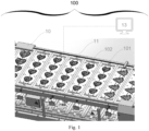
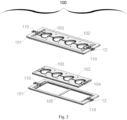
- FIGs. 1 , 2 , 3 and 4 show general and detailed views of said slat exchange system in thermo-welding machines having cells or alveolar cavities 100 according to the present invention.
- FIG. 1 as in the following description, the embodiment of the present invention currently considered the best is illustrated.
- Said slat exchange system in thermo-welding machines having cells or alveolar cavities 100 adapted to be adopted on a thermo-welding machine having cells or alveolar cavities 10 having a chain conveyor 11, a transmission chain 12, an IT management apparatus 13, comprises at least one fixed slat part 101 with a contrast bar 105, at least one movable slat part 102 with shapes 103 and a symmetric groove 104, at least one hooking and unhooking mechanism 110 with at least one pin 111, at least one handle 112 and at least one bar with spring 113, a check sensor 120, a robot 130, a profiled stick 140.
- FIG. 1 shows a perspective view of said thermo-welding machine having cells or alveolar cavities 10 with said chain conveyor 11, on which various units of said fixed slat part 101 and said removable slat part 102 are arranged in series.
- FIG. 2 shows a detail of said fixed slat part 101 and said removable slat part 102 in the constrained and released configurations, it is in fact possible to observe said removable slat part 102 inserted inside or released and shown on the outside of said fixed slat part, and it is possible to observe said hooking and unhooking mechanism 110 and said contrast bar 105.
- Said hooking and unhooking mechanism 110 is shown in detail in FIG. 3 in the locked and unlocked configuration.
- said pin 111 In the locked configuration, said pin 111 is located inside said symmetric groove 104 of said removable slat part 102 and said bar with spring 113 is in a rest condition.
- said pin 111 In the unlocked configuration, said pin 111 is moved back within the shape of said fixed slat part 101, applying force on said handle 112 and said bar with spring 113 is in a compressed condition, in this configuration said removable slat part 102 is released and can therefore be extracted from said fixed slat part 101.
- FIG. 4 lastly shows a perspective view of the portion of the thermo-welding machine having cells or alveolar cavities 10 where said check sensor 120, said robot 130, and two units of said profiled stick 140 are installed.
- the units of said profiled stick rod 140 ensure that said handle 112 of three units of said hooking and unhooking mechanism 110 slide simultaneously and position themselves in the unlocking configuration to subsequently allow said robot 130 to move said removable slat part 102.
Landscapes
- Engineering & Computer Science (AREA)
- Mechanical Engineering (AREA)
- Manufacturing & Machinery (AREA)
- Robotics (AREA)
- Health & Medical Sciences (AREA)
- Heart & Thoracic Surgery (AREA)
- Lining Or Joining Of Plastics Or The Like (AREA)
- Package Closures (AREA)
Claims (11)
- Système de remplacement de latte (100) dans des machines de thermosoudage ayant des cellules ou des cavités alvéolaires, adapté pour être utilisé sur une machine de thermosoudage (10) à cellules ou alvéoles ayant un transporteur à chaîne (11), une chaîne de transmission (12) et un appareil de gestion informatique (13), au moins une partie de latte fixe (101) reliée en permanence audit transporteur à chaîne (11) ; au moins une partie de latte amovible (102) ayant un(e) ou plusieurs formes/profils (103) et adaptée pour être accrochée à ladite partie de latte fixe (101) et décrochée de celle-ci de manière réversible afin d'être remplacée par une autre partie de latte amovible (102) ayant des formes/profils (103) différents et/ou pour des raisons d'entretien ; dans lequel ladite partie de latte amovible (102) est dotée d'une rainure symétrique (104) agencée à une position centrale à l'intérieur d'une épaisseur de paroi de ladite partie de latte amovible (102) ; ledit système étant caractérisé en ce qu'il comprend : au moins un mécanisme d'accrochage et de décrochage (110) installé sur ladite partie de latte fixe (101), adapté pour permettre l'accrochage et le décrochage de ladite partie de latte amovible (102) afin de favoriser un remplacement/échange rapide de cette dernière.
- Système de remplacement de latte (100) dans des machines de thermosoudage ayant des cellules ou des cavités alvéolaires, selon la revendication 1 précédente, caractérisé en ce que ledit mécanisme d'accrochage et de décrochage (110) comporte :- au moins une broche (111) configurée pour être insérée dans ladite rainure symétrique (104) afin de venir en prise avec ladite partie de latte amovible (102) ; ladite broche (111) étant dotée d'une partie inférieure plate afin de verrouiller ladite partie de latte amovible (102) et d'une partie supérieure oblique afin de permettre une insertion facilitée de ladite partie de latte amovible (102) ;- au moins une poignée (112), pouvant être reliée à ladite broche (111) et faisant saillie au-delà de ladite partie de latte fixe (101) pour faciliter sa manipulation ;- au moins une barre à ressort (113), adaptée pour permettre le coulissement vers l'arrière de ladite broche (111) lorsqu'à l'aide de la poignée (112), celle-ci est rétractée à l'intérieur du profil de ladite partie de latte fixe (101) ; et adaptée pour être remise dans une position avancée, poussant cette broche (111) dans ladite rainure symétrique (104) de ladite partie de latte amovible (102).
- Système de remplacement de latte (100) dans des machines de thermosoudage ayant des cellules ou des cavités alvéolaires, selon les revendications 1 ou 2 précédentes, caractérisé en ce que ladite partie de latte fixe (101) comprend une barre de retenue ou une barre de contre-pression (105), dans une zone inférieure, afin de fournir un support pendant l'accrochage de ladite partie de latte amovible (102), ainsi que pendant le travail/traitement réalisé par ladite machine de thermosoudage (10) à cellules ou alvéoles.
- Système de remplacement de latte (100) dans des machines de thermosoudage ayant des cellules ou des cavités alvéolaires, selon l'une des revendications précédentes, caractérisé en ce que ladite partie de latte amovible (102) est utilisable sur ses deux côtés, permettant ainsi l'utilisation de formes/profils (103) sur sa partie supérieure et l'utilisation d'autres formes/profils (103) sur sa partie inférieure, tout en éliminant le besoin d'employer un autre jeu de lattes.
- Système de remplacement de latte (100) dans des machines de thermosoudage ayant des cellules ou des cavités alvéolaires, selon l'une des revendications précédentes, caractérisé en ce que ladite partie de latte amovible (102) est configurée de manière à permettre l'assemblage de plusieurs modules (106) qui peuvent être déplacés et combinés les uns avec les autres, de façon à permettre la disponibilité d'un plus grand nombre de formes/profils (103) et à assurer une polyvalence accrue.
- Système de remplacement de latte (100) dans des machines de thermosoudage ayant des cellules ou des cavités alvéolaires, selon l'une des revendications précédentes, caractérisé en ce qu'il comprend un capteur de contrôle (120) adapté pour analyser l'alignement entre ladite partie de latte amovible (102) et ladite partie de latte fixe (101) et pour vérifier un positionnement correct de celles-ci ; dans lequel, si ledit capteur de contrôle (120) détecte un alignement incorrect entre ladite partie de latte amovible (102) et ladite partie de latte fixe (101), la machine de thermosoudage à alvéoles (10) est arrêtée et un avertissement est envoyé pour empêcher un endommagement de la latte et/ou de la machine.
- Système d'échange de latte (100) dans des machines de thermosoudage ayant des cellules ou des cavités alvéolaires, selon la revendication 6 précédente, caractérisé en ce que ledit capteur de contrôle (120) est adapté pour mesurer une distance entre un bord de ladite partie de latte fixe (101) et les extrémités desdit(e)s formes/profils (103) et pour la communiquer audit appareil de gestion informatique (13) ; dans lequel, au début du travail, ledit appareil de gestion informatique (13) reçoit les données concernant toutes les distances entre le bord de ladite partie de latte fixe (101) et les extrémités desdit(e)s formes/profils (103), et si celles-ci diffèrent des distances mesurées par le capteur de contrôle (120), celui-ci arrête ladite machine de thermosoudage à alvéoles (10) et envoie un avertissement au panneau de commande en communiquant le format réel monté sur le transporteur à chaîne ; dans lequel ledit capteur de contrôle (120) est également adapté pour empêcher des dommages accidentels lorsque ladite partie de latte amovible (102) a des formes/profils (103) différents de ceux nécessaires pour le processus.
- Système de remplacement de latte (100) dans des machines de thermosoudage ayant des cellules ou des cavités alvéolaires, selon l'une des revendications précédentes, caractérisé en ce qu'il comprend un robot (130) adapté pour décrocher ladite partie de latte amovible (102), en agissant automatiquement sur ledit mécanisme d'accrochage et de décrochage (110) ; dans lequel, ledit robot (130) est adapté pour mettre en prise/accrocher ladite partie de latte amovible (102) avec/à ladite partie de latte fixe (101) en permettant à ladite partie de latte amovible (102) d'atteindre sa position de repos à l'intérieur de ladite partie de latte fixe (101).
- Système de remplacement de latte (100) dans des machines de thermosoudage ayant des cellules ou des cavités alvéolaires, selon l'une des revendications précédentes, caractérisé en ce qu'il comprend une barre profilée (140) fixée dans une position le long dudit transporteur à chaîne (11) de ladite machine de thermosoudage à alvéoles (10) et appropriée pour déverrouiller automatiquement ledit mécanisme d'accrochage et de décrochage (110) en provoquant le coulissement de ladite poignée (112), afin de faciliter l'opération manuelle de retrait, ou le retrait dudit robot (130), de ladite partie de latte amovible (102) ; dans lequel ladite barre profilée (140) a une longueur adaptée pour permettre le décrochage d'une ou plusieurs unités de mécanismes d'accrochage et de décrochage (110).
- Système de remplacement de latte (100) dans des machines de thermosoudage ayant des cellules ou des cavités alvéolaires, au moins selon la revendication 2 précédente, caractérisé en ce que ladite broche (111) peut coulisser en utilisant ladite barre à ressort (113) ou au moyen de systèmes magnétiques, électromagnétiques ou hydrauliques, et/ou d'autres types de systèmes.
- Système de remplacement de latte (100) dans des machines de thermosoudage ayant des cellules ou des cavités alvéolaires, au moins selon la revendication 2 précédente, caractérisé en ce que ledit mécanisme d'accrochage et de décrochage (110) peut être mis en œuvre par différents systèmes d'actionnement, par exemple magnétiques, pneumatiques ou électriques.
Applications Claiming Priority (1)
| Application Number | Priority Date | Filing Date | Title |
|---|---|---|---|
| IT102022000019590A IT202200019590A1 (it) | 2022-09-23 | 2022-09-23 | Sistema di cambio doghe in termosaldatrici ad alveoli |
Publications (3)
| Publication Number | Publication Date |
|---|---|
| EP4342806A1 EP4342806A1 (fr) | 2024-03-27 |
| EP4342806B1 true EP4342806B1 (fr) | 2024-11-13 |
| EP4342806C0 EP4342806C0 (fr) | 2024-11-13 |
Family
ID=84370532
Family Applications (1)
| Application Number | Title | Priority Date | Filing Date |
|---|---|---|---|
| EP23197964.2A Active EP4342806B1 (fr) | 2022-09-23 | 2023-09-18 | Système d'échange de lattes dans des machines de thermosoudage ayant des cellules ou des cavités alvéolaires |
Country Status (4)
| Country | Link |
|---|---|
| US (1) | US12570425B2 (fr) |
| EP (1) | EP4342806B1 (fr) |
| ES (1) | ES3010266T3 (fr) |
| IT (1) | IT202200019590A1 (fr) |
Families Citing this family (1)
| Publication number | Priority date | Publication date | Assignee | Title |
|---|---|---|---|---|
| EP4717618A1 (fr) * | 2024-09-19 | 2026-04-01 | KOCH Pac-Systeme GmbH | Porte-pièce, dispositif de manipulation et machine d'emballage |
Family Cites Families (6)
| Publication number | Priority date | Publication date | Assignee | Title |
|---|---|---|---|---|
| FR2963322B1 (fr) * | 2010-08-02 | 2012-08-03 | Guelt | Dispositif d'operculage avec plaques support interchangeables pour supporter des contenants de formats differents |
| ITMI20132079A1 (it) | 2013-12-13 | 2015-06-14 | Antonio Rossini | Dispositivo per il confezionamento. |
| CN208976599U (zh) | 2018-11-14 | 2019-06-14 | 十堰坤钰渝明汽车零部件有限公司 | 一种可快速互换通用性热成型冲切模具组 |
| DE102019206389A1 (de) * | 2019-05-03 | 2020-11-05 | Multivac Sepp Haggenmüller Se & Co. Kg | Verfahren zur erkennung von werkzeugfehlstellung und verpackungsmaschine |
| CN111645951A (zh) | 2020-06-17 | 2020-09-11 | 陈淑华 | 一种用于食品包装袋的快速热封装置 |
| CN112810863A (zh) | 2021-01-30 | 2021-05-18 | 佛山市创利宝包装机械有限公司 | 一种热封食品包装机 |
-
2022
- 2022-09-23 IT IT102022000019590A patent/IT202200019590A1/it unknown
-
2023
- 2023-09-18 ES ES23197964T patent/ES3010266T3/es active Active
- 2023-09-18 EP EP23197964.2A patent/EP4342806B1/fr active Active
- 2023-09-21 US US18/471,983 patent/US12570425B2/en active Active
Also Published As
| Publication number | Publication date |
|---|---|
| US12570425B2 (en) | 2026-03-10 |
| IT202200019590A1 (it) | 2024-03-23 |
| EP4342806C0 (fr) | 2024-11-13 |
| US20240101296A1 (en) | 2024-03-28 |
| EP4342806A1 (fr) | 2024-03-27 |
| ES3010266T3 (en) | 2025-04-01 |
Similar Documents
| Publication | Publication Date | Title |
|---|---|---|
| EP4342806B1 (fr) | Système d'échange de lattes dans des machines de thermosoudage ayant des cellules ou des cavités alvéolaires | |
| US20130212988A1 (en) | Method for Changing the Upper and Lower Tool of a Packaging Machine | |
| EP3944937B1 (fr) | Découpeuse pour des aliments avec appareil de charge | |
| US10308435B2 (en) | Apparatuses and methods for producing containers | |
| EP3140091B1 (fr) | Appareil de tranchage de produit alimentaire | |
| EP2522580B1 (fr) | Dispositif de changement d'outil | |
| EP2439027B1 (fr) | Machine pour la coupe des alliments | |
| CN108973151B (zh) | 一种托盘焊接流水线 | |
| US12042841B2 (en) | Metal sheet bending machine | |
| EP3863778B1 (fr) | Machine à plier pour feuilles métalliques dotée d'un magasin d'outils | |
| FI101202B (fi) | Menetelmä ja laite puun lastutuskoneessa olevien jälkihiottavien terie n automaattiseksi vaihtamiseksi | |
| CN105292559A (zh) | 泡罩包装机 | |
| EP3300491B1 (fr) | Module de groupage sans fin avec un charriot et procédé | |
| WO2004080683A2 (fr) | Procede et systeme de thermoformage de feuilles doubles | |
| EP2590790B1 (fr) | Procédé de chargement et de déchargement d'un moule sur une machine de moulage de plastique en mousse | |
| US6161471A (en) | Machine for the automatic production of meat or vegetable brochettes spitted on wooden picks in particular | |
| EP1038778B1 (fr) | Dispositif pour l'emballage automatique de marchandises dans des récipients tels que des godets et analogues | |
| US20170320260A1 (en) | Apparatus for thermoforming plastic containers | |
| EP1074335A2 (fr) | Changement de mandrin et d'outil et dispositif pour cela | |
| IT201900002807A1 (it) | Stazione di carico e impianto di lavorazione di porzioni di carne dotato di detta stazione di carico e di una stazione di scarico | |
| US11572204B2 (en) | Reconfigurable device for dispensing/distributing tablets in blister pockets of a packaging strip of a machine of blister-pack packaging type | |
| CN223763368U (zh) | 一种便于更换切刀的裁切机 | |
| KR102941035B1 (ko) | 수직 적층형 자동 원료 공급장치 | |
| CN120418157A (zh) | 包装机的工作站和从包装机的工作站中取出下模的方法 | |
| EP0290401A2 (fr) | Machine de thermoformage |
Legal Events
| Date | Code | Title | Description |
|---|---|---|---|
| PUAI | Public reference made under article 153(3) epc to a published international application that has entered the european phase |
Free format text: ORIGINAL CODE: 0009012 |
|
| STAA | Information on the status of an ep patent application or granted ep patent |
Free format text: STATUS: THE APPLICATION HAS BEEN PUBLISHED |
|
| AK | Designated contracting states |
Kind code of ref document: A1 Designated state(s): AL AT BE BG CH CY CZ DE DK EE ES FI FR GB GR HR HU IE IS IT LI LT LU LV MC ME MK MT NL NO PL PT RO RS SE SI SK SM TR |
|
| STAA | Information on the status of an ep patent application or granted ep patent |
Free format text: STATUS: REQUEST FOR EXAMINATION WAS MADE |
|
| 17P | Request for examination filed |
Effective date: 20240528 |
|
| RBV | Designated contracting states (corrected) |
Designated state(s): AL AT BE BG CH CY CZ DE DK EE ES FI FR GB GR HR HU IE IS IT LI LT LU LV MC ME MK MT NL NO PL PT RO RS SE SI SK SM TR |
|
| GRAP | Despatch of communication of intention to grant a patent |
Free format text: ORIGINAL CODE: EPIDOSNIGR1 |
|
| STAA | Information on the status of an ep patent application or granted ep patent |
Free format text: STATUS: GRANT OF PATENT IS INTENDED |
|
| RIC1 | Information provided on ipc code assigned before grant |
Ipc: B65B 9/04 20060101ALN20240626BHEP Ipc: B29C 65/00 20060101ALI20240626BHEP Ipc: B65B 59/04 20060101ALI20240626BHEP Ipc: B65B 59/00 20060101ALI20240626BHEP Ipc: B65B 51/14 20060101AFI20240626BHEP |
|
| INTG | Intention to grant announced |
Effective date: 20240709 |
|
| GRAS | Grant fee paid |
Free format text: ORIGINAL CODE: EPIDOSNIGR3 |
|
| GRAA | (expected) grant |
Free format text: ORIGINAL CODE: 0009210 |
|
| STAA | Information on the status of an ep patent application or granted ep patent |
Free format text: STATUS: THE PATENT HAS BEEN GRANTED |
|
| AK | Designated contracting states |
Kind code of ref document: B1 Designated state(s): AL AT BE BG CH CY CZ DE DK EE ES FI FR GB GR HR HU IE IS IT LI LT LU LV MC ME MK MT NL NO PL PT RO RS SE SI SK SM TR |
|
| REG | Reference to a national code |
Ref country code: GB Ref legal event code: FG4D |
|
| REG | Reference to a national code |
Ref country code: CH Ref legal event code: EP |
|
| REG | Reference to a national code |
Ref country code: IE Ref legal event code: FG4D |
|
| REG | Reference to a national code |
Ref country code: DE Ref legal event code: R096 Ref document number: 602023001020 Country of ref document: DE |
|
| U01 | Request for unitary effect filed |
Effective date: 20241120 |
|
| U07 | Unitary effect registered |
Designated state(s): AT BE BG DE DK EE FI FR IT LT LU LV MT NL PT RO SE SI Effective date: 20241127 |
|
| REG | Reference to a national code |
Ref country code: ES Ref legal event code: FG2A Ref document number: 3010266 Country of ref document: ES Kind code of ref document: T3 Effective date: 20250401 |
|
| PG25 | Lapsed in a contracting state [announced via postgrant information from national office to epo] |
Ref country code: HR Free format text: LAPSE BECAUSE OF FAILURE TO SUBMIT A TRANSLATION OF THE DESCRIPTION OR TO PAY THE FEE WITHIN THE PRESCRIBED TIME-LIMIT Effective date: 20241113 Ref country code: IS Free format text: LAPSE BECAUSE OF FAILURE TO SUBMIT A TRANSLATION OF THE DESCRIPTION OR TO PAY THE FEE WITHIN THE PRESCRIBED TIME-LIMIT Effective date: 20250313 |
|
| PG25 | Lapsed in a contracting state [announced via postgrant information from national office to epo] |
Ref country code: NO Free format text: LAPSE BECAUSE OF FAILURE TO SUBMIT A TRANSLATION OF THE DESCRIPTION OR TO PAY THE FEE WITHIN THE PRESCRIBED TIME-LIMIT Effective date: 20250213 |
|
| PG25 | Lapsed in a contracting state [announced via postgrant information from national office to epo] |
Ref country code: GR Free format text: LAPSE BECAUSE OF FAILURE TO SUBMIT A TRANSLATION OF THE DESCRIPTION OR TO PAY THE FEE WITHIN THE PRESCRIBED TIME-LIMIT Effective date: 20250214 |
|
| PG25 | Lapsed in a contracting state [announced via postgrant information from national office to epo] |
Ref country code: PL Free format text: LAPSE BECAUSE OF FAILURE TO SUBMIT A TRANSLATION OF THE DESCRIPTION OR TO PAY THE FEE WITHIN THE PRESCRIBED TIME-LIMIT Effective date: 20241113 |
|
| PG25 | Lapsed in a contracting state [announced via postgrant information from national office to epo] |
Ref country code: RS Free format text: LAPSE BECAUSE OF FAILURE TO SUBMIT A TRANSLATION OF THE DESCRIPTION OR TO PAY THE FEE WITHIN THE PRESCRIBED TIME-LIMIT Effective date: 20250213 |
|
| PG25 | Lapsed in a contracting state [announced via postgrant information from national office to epo] |
Ref country code: SM Free format text: LAPSE BECAUSE OF FAILURE TO SUBMIT A TRANSLATION OF THE DESCRIPTION OR TO PAY THE FEE WITHIN THE PRESCRIBED TIME-LIMIT Effective date: 20241113 |
|
| PG25 | Lapsed in a contracting state [announced via postgrant information from national office to epo] |
Ref country code: SK Free format text: LAPSE BECAUSE OF FAILURE TO SUBMIT A TRANSLATION OF THE DESCRIPTION OR TO PAY THE FEE WITHIN THE PRESCRIBED TIME-LIMIT Effective date: 20241113 |
|
| PG25 | Lapsed in a contracting state [announced via postgrant information from national office to epo] |
Ref country code: CZ Free format text: LAPSE BECAUSE OF FAILURE TO SUBMIT A TRANSLATION OF THE DESCRIPTION OR TO PAY THE FEE WITHIN THE PRESCRIBED TIME-LIMIT Effective date: 20241113 |
|
| U20 | Renewal fee for the european patent with unitary effect paid |
Year of fee payment: 3 Effective date: 20250709 |
|
| PLBE | No opposition filed within time limit |
Free format text: ORIGINAL CODE: 0009261 |
|
| STAA | Information on the status of an ep patent application or granted ep patent |
Free format text: STATUS: NO OPPOSITION FILED WITHIN TIME LIMIT |
|
| 26N | No opposition filed |
Effective date: 20250814 |
|
| PGFP | Annual fee paid to national office [announced via postgrant information from national office to epo] |
Ref country code: ES Payment date: 20251030 Year of fee payment: 3 |