EP4348012B1 - Turbomachine comprenant une machine électrique intégrée à l'arrière - Google Patents
Turbomachine comprenant une machine électrique intégrée à l'arrière Download PDFInfo
- Publication number
- EP4348012B1 EP4348012B1 EP22731746.8A EP22731746A EP4348012B1 EP 4348012 B1 EP4348012 B1 EP 4348012B1 EP 22731746 A EP22731746 A EP 22731746A EP 4348012 B1 EP4348012 B1 EP 4348012B1
- Authority
- EP
- European Patent Office
- Prior art keywords
- turbomachine
- stator
- low
- sleeve
- pressure shaft
- Prior art date
- Legal status (The legal status is an assumption and is not a legal conclusion. Google has not performed a legal analysis and makes no representation as to the accuracy of the status listed.)
- Active
Links
Images


Classifications
-
- F—MECHANICAL ENGINEERING; LIGHTING; HEATING; WEAPONS; BLASTING
- F01—MACHINES OR ENGINES IN GENERAL; ENGINE PLANTS IN GENERAL; STEAM ENGINES
- F01D—NON-POSITIVE DISPLACEMENT MACHINES OR ENGINES, e.g. STEAM TURBINES
- F01D15/00—Adaptations of machines or engines for special use; Combinations of engines with devices driven thereby
- F01D15/10—Adaptations for driving, or combinations with, electric generators
-
- F—MECHANICAL ENGINEERING; LIGHTING; HEATING; WEAPONS; BLASTING
- F01—MACHINES OR ENGINES IN GENERAL; ENGINE PLANTS IN GENERAL; STEAM ENGINES
- F01D—NON-POSITIVE DISPLACEMENT MACHINES OR ENGINES, e.g. STEAM TURBINES
- F01D25/00—Component parts, details, or accessories, not provided for in, or of interest apart from, other groups
- F01D25/16—Arrangement of bearings; Supporting or mounting bearings in casings
-
- F—MECHANICAL ENGINEERING; LIGHTING; HEATING; WEAPONS; BLASTING
- F01—MACHINES OR ENGINES IN GENERAL; ENGINE PLANTS IN GENERAL; STEAM ENGINES
- F01D—NON-POSITIVE DISPLACEMENT MACHINES OR ENGINES, e.g. STEAM TURBINES
- F01D25/00—Component parts, details, or accessories, not provided for in, or of interest apart from, other groups
- F01D25/18—Lubricating arrangements
-
- F—MECHANICAL ENGINEERING; LIGHTING; HEATING; WEAPONS; BLASTING
- F01—MACHINES OR ENGINES IN GENERAL; ENGINE PLANTS IN GENERAL; STEAM ENGINES
- F01D—NON-POSITIVE DISPLACEMENT MACHINES OR ENGINES, e.g. STEAM TURBINES
- F01D25/00—Component parts, details, or accessories, not provided for in, or of interest apart from, other groups
- F01D25/30—Exhaust heads, chambers, or the like
-
- F—MECHANICAL ENGINEERING; LIGHTING; HEATING; WEAPONS; BLASTING
- F02—COMBUSTION ENGINES; HOT-GAS OR COMBUSTION-PRODUCT ENGINE PLANTS
- F02C—GAS-TURBINE PLANTS; AIR INTAKES FOR JET-PROPULSION PLANTS; CONTROLLING FUEL SUPPLY IN AIR-BREATHING JET-PROPULSION PLANTS
- F02C7/00—Features, components parts, details or accessories, not provided for in, or of interest apart form groups F02C1/00 - F02C6/00; Air intakes for jet-propulsion plants
- F02C7/06—Arrangements of bearings; Lubricating
-
- F—MECHANICAL ENGINEERING; LIGHTING; HEATING; WEAPONS; BLASTING
- F02—COMBUSTION ENGINES; HOT-GAS OR COMBUSTION-PRODUCT ENGINE PLANTS
- F02C—GAS-TURBINE PLANTS; AIR INTAKES FOR JET-PROPULSION PLANTS; CONTROLLING FUEL SUPPLY IN AIR-BREATHING JET-PROPULSION PLANTS
- F02C7/00—Features, components parts, details or accessories, not provided for in, or of interest apart form groups F02C1/00 - F02C6/00; Air intakes for jet-propulsion plants
- F02C7/32—Arrangement, mounting, or driving, of auxiliaries
-
- F—MECHANICAL ENGINEERING; LIGHTING; HEATING; WEAPONS; BLASTING
- F02—COMBUSTION ENGINES; HOT-GAS OR COMBUSTION-PRODUCT ENGINE PLANTS
- F02C—GAS-TURBINE PLANTS; AIR INTAKES FOR JET-PROPULSION PLANTS; CONTROLLING FUEL SUPPLY IN AIR-BREATHING JET-PROPULSION PLANTS
- F02C7/00—Features, components parts, details or accessories, not provided for in, or of interest apart form groups F02C1/00 - F02C6/00; Air intakes for jet-propulsion plants
- F02C7/36—Power transmission arrangements between the different shafts of the gas turbine plant, or between the gas-turbine plant and the power user
-
- H—ELECTRICITY
- H02—GENERATION; CONVERSION OR DISTRIBUTION OF ELECTRIC POWER
- H02K—DYNAMO-ELECTRIC MACHINES
- H02K1/00—Details of the magnetic circuit
- H02K1/06—Details of the magnetic circuit characterised by the shape, form or construction
- H02K1/12—Stationary parts of the magnetic circuit
- H02K1/18—Means for mounting or fastening magnetic stationary parts on to, or to, the stator structures
- H02K1/185—Means for mounting or fastening magnetic stationary parts on to, or to, the stator structures to outer stators
-
- H—ELECTRICITY
- H02—GENERATION; CONVERSION OR DISTRIBUTION OF ELECTRIC POWER
- H02K—DYNAMO-ELECTRIC MACHINES
- H02K1/00—Details of the magnetic circuit
- H02K1/06—Details of the magnetic circuit characterised by the shape, form or construction
- H02K1/22—Rotating parts of the magnetic circuit
- H02K1/28—Means for mounting or fastening rotating magnetic parts on to, or to, the rotor structures
- H02K1/30—Means for mounting or fastening rotating magnetic parts on to, or to, the rotor structures using intermediate parts, e.g. spiders
-
- H—ELECTRICITY
- H02—GENERATION; CONVERSION OR DISTRIBUTION OF ELECTRIC POWER
- H02K—DYNAMO-ELECTRIC MACHINES
- H02K7/00—Arrangements for handling mechanical energy structurally associated with dynamo-electric machines, e.g. structural association with mechanical driving motors or auxiliary dynamo-electric machines
- H02K7/08—Structural association with bearings
- H02K7/083—Structural association with bearings radially supporting the rotary shaft at both ends of the rotor
-
- H—ELECTRICITY
- H02—GENERATION; CONVERSION OR DISTRIBUTION OF ELECTRIC POWER
- H02K—DYNAMO-ELECTRIC MACHINES
- H02K7/00—Arrangements for handling mechanical energy structurally associated with dynamo-electric machines, e.g. structural association with mechanical driving motors or auxiliary dynamo-electric machines
- H02K7/18—Structural association of electric generators with mechanical driving motors, e.g. with turbines
- H02K7/1807—Rotary generators
- H02K7/1823—Rotary generators structurally associated with turbines or similar engines
-
- H—ELECTRICITY
- H02—GENERATION; CONVERSION OR DISTRIBUTION OF ELECTRIC POWER
- H02K—DYNAMO-ELECTRIC MACHINES
- H02K9/00—Arrangements for cooling or ventilating
- H02K9/19—Arrangements for cooling or ventilating for machines with closed casing and closed-circuit cooling using a liquid cooling medium, e.g. oil
-
- F—MECHANICAL ENGINEERING; LIGHTING; HEATING; WEAPONS; BLASTING
- F05—INDEXING SCHEMES RELATING TO ENGINES OR PUMPS IN VARIOUS SUBCLASSES OF CLASSES F01-F04
- F05D—INDEXING SCHEME FOR ASPECTS RELATING TO NON-POSITIVE-DISPLACEMENT MACHINES OR ENGINES, GAS-TURBINES OR JET-PROPULSION PLANTS
- F05D2220/00—Application
- F05D2220/70—Application in combination with
- F05D2220/76—Application in combination with an electrical generator
-
- F—MECHANICAL ENGINEERING; LIGHTING; HEATING; WEAPONS; BLASTING
- F05—INDEXING SCHEMES RELATING TO ENGINES OR PUMPS IN VARIOUS SUBCLASSES OF CLASSES F01-F04
- F05D—INDEXING SCHEME FOR ASPECTS RELATING TO NON-POSITIVE-DISPLACEMENT MACHINES OR ENGINES, GAS-TURBINES OR JET-PROPULSION PLANTS
- F05D2220/00—Application
- F05D2220/70—Application in combination with
- F05D2220/76—Application in combination with an electrical generator
- F05D2220/766—Application in combination with an electrical generator via a direct connection, i.e. a gearless transmission
-
- F—MECHANICAL ENGINEERING; LIGHTING; HEATING; WEAPONS; BLASTING
- F05—INDEXING SCHEMES RELATING TO ENGINES OR PUMPS IN VARIOUS SUBCLASSES OF CLASSES F01-F04
- F05D—INDEXING SCHEME FOR ASPECTS RELATING TO NON-POSITIVE-DISPLACEMENT MACHINES OR ENGINES, GAS-TURBINES OR JET-PROPULSION PLANTS
- F05D2260/00—Function
- F05D2260/40—Transmission of power
- F05D2260/403—Transmission of power through the shape of the drive components
Definitions
- the present invention relates to a turbomachine, in which an electric machine is integrated at the rear.
- This electric machine can be a pure electric generator, or a reversible machine that can also work as an electric motor; it is added to the electric machine traditionally placed on a gearbox at the periphery of the turbomachine to provide it and other aircraft equipment with the electrical energy they need.
- a turbomachine comprising an electric machine integrated at the rear, is described in the document FR 3 027 625 A1 .
- EP 3613977 A1 describes an electric machine at the rear of a turbomachine and detachable from the turbomachine by modules, which seems to make this document the closest to the invention.
- EP 3763929 A1 describes the mounting of an electric machine at the end of a high-pressure shaft of a turbomachine, in which the rotor of the electric machine is mounted on a sliding shaft end which extends the high-pressure shaft.
- FR 3073569 A1 describes an electric machine mounted on a propeller shaft of a turboprop, with a disengageable rotor.
- EP 3246528 A1 And EP 3708787 A1 describe other turbomachines equipped with electric machines.
- the rotor of the electric machine cannot in reality be mounted directly on the low pressure shaft, because it must be able to be decoupled from it in certain failure situations, for example short circuits, particularly in the case where the electric machine has permanent magnets. It is therefore necessary to add a decoupling device between the low pressure shaft and the rotor of the electric machine, and to support the rotor by independent bearings. The device is then made heavier, and the problems of layout and resistance to dynamic stresses risk becoming more acute. The additional bearings and the decoupling device must themselves withstand the high heat to which they are subjected.
- the invention encompasses several measures which make it possible, separately and in combination, to reduce or eliminate the difficulties mentioned above.
- the arrangement obtained at the rear of the turbomachine is relatively simple, compact, easily dismantled, and relatively undisturbing of the dynamic balances of the low-pressure shaft; excessive heating is finally little to fear.
- the invention thus relates to a turbomachine comprising a low-pressure shaft, extending along an axis of the turbomachine which defines a front and a rear; a turbomachine stator supporting the low-pressure shaft by bearings including a rear bearing; an electric machine located at a rear part of the turbomachine, and comprising a rotor driven in a disconnectable manner by the low-pressure shaft and a stator fixed to the stator of the turbomachine; comprising a support journal for the rotor of the electric machine, comprising a shaft section fixed in a releasable manner to a rear end of the low-pressure shaft by extending the low-pressure shaft, an armature to which the rotor of the electric machine is fixed and which surrounds the shaft section; characterized in that the stator of the electric machine surrounds the rotor of the electric machine; and in that the turbomachine further comprises at least one bearing mounted between the armature and the shaft section; and a
- a low pressure shaft a shaft associated with the rotation of a turbine at the very rear of the turbomachine, and which therefore extends further back than other possible shafts such as a high pressure shaft.
- the components of the electric machine can be placed in a cavity at the rear of the turbomachine, into which the end of the low-pressure shaft opens and which is closed at the rear by a conical cover.
- the bearing journal of the rotor of the turbomachine forms a unitary assembly which can be easily fixed to the end of the low-pressure shaft, and the stator of the machine can be fixed to the stator of the turbomachine, without almost modifying the design of existing turbomachines without the electric machine.
- the elongation of the low-pressure shaft due to the addition of the shaft section, and the rotor overhang, are moderate.
- the bearing or bearings integrated into the journal can easily be lubricated by a stand-alone device, separate from the lubrication devices dedicated to the support bearings of the low-pressure shaft and the high-pressure shaft, therefore without further modifying the existing lubrication circuits.
- the coupling sleeve removably connecting in rotation the low-pressure shaft and the rotor of the electric machine is compact and occupies, without difficulty in designing it, an empty volume still present around the end of the low-pressure shaft and behind the stator of the turbomachine. It is also easy to control, and does not introduce significant dynamic disturbances. And the disassembly of the various components (journal, coupling sleeve and stator of the electric machine) can be accomplished easily.
- bearing or bearings it is advantageous for the bearing or bearings to be lubricated with grease, by being contained in a closed lubrication enclosure.
- a dynamic lubrication, usual for turbomachines, by forced circulation of oil is in fact not necessary for these particular bearings, which are inactive in the usual state of driving the rotor of the electric machine, in which the coupling sleeve secures in rotation the armature with the low pressure shaft and the shaft section.
- a rotation between the armature and the shaft section exists only in the conditions of failures of the electric machine, during which a decoupling of the sleeve is ordered.
- Friction and heat are then produced by the bearings arranged between the shaft section and the rotor, but this state is generally brief, and the heat produced is then insufficient to produce significant damage. Such damage is likely to concern only the bearings, which can be easily replaced. And the surrounding heat, produced by the service of the turbomachine, is largely absorbed by the already existing fluid circulation cooling devices, which serve the parts near the journal: the heating it undergoes remains moderate even in the absence of a particular cooling device.
- the enclosure can be supplied with grease whatever the circumstances: it is then recommended that the shaft section be hollow and contain a grease reservoir which communicates with the enclosure by at least one hole.
- the grease in the reservoir can also help to lubricate the coupling devices between the sleeve on the one hand, and the armature, the low-pressure shaft or the shaft section on the other.
- the lubrication enclosure is then partly delimited by these parts.
- the coupling devices may be networks of radially or axially oriented grooves, depending on whether the connection between the parts they connect is to be interrupted or maintained during their axial movements from one state to another.
- the turbomachine further comprises a sleeve actuator which is housed axially between the turbomachine stator and the armature, and radially between the armature and the sleeve.
- a simple and advantageous design of the actuator comprises at least one axially movable roller freely rotating about a radial axis, capable of abutting against a flat collar of the sleeve and of pushing the collar.
- the arrangement advantageously comprises a spring engaged around the low pressure shaft, and compressed between the low pressure shaft and the sleeve.
- Disassembly is then easy if the shaft section contains a hollow, the nut includes tool-gripping reliefs which protrude into the hollow, and the nut includes an anti-rotation brake placed in the hollow.
- the shaft section contains a grease reservoir
- the reservoir could occupy only a peripheral part of the internal volume of the shaft section, in order to more easily access the fixing nut, through the central part of the internal volume, which then remains empty.
- journal is separable from the low pressure shaft and the sleeve by sliding backwards
- the sleeve is fixed to the turbomachine stator by a first bolted flange accessible from the rear
- stator of the electric machine is fixed to the stator of the turbomachine by a second bolted flange accessible from the rear.
- journal, the sleeve, the stator of the electric machine, and the actuator when it is also present at the rear of the turbomachine are formed in separate and unitary modules, successively removable from the turbomachine (and reassembled in the same way).
- Their modular, separate and unitary nature means that they form independent portions of the device, each of which is brought or removed as a block, that they are assembled to the rest of the turbomachine without necessarily being assembled together, and that they are separately replaceable.
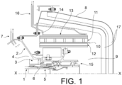
- the turbomachine comprises a central axis XX extending in a longitudinal direction, between a forward direction (on the left of the figures) and a rearward direction (on the right of the figures). Only the rear part of the turbomachine near the axis XX is shown, the rest of the turbomachine not being modified by the invention.
- the turbomachine comprises a low-pressure shaft 1 arranged in the axis XX and rotating about this axis. It comprises a stator 2 in which the low-pressure shaft 1 is supported by various bearings, including a rear bearing, which is the furthest rear of the bearings by means of which the low-pressure shaft 1 is supported by the stator 2.
- the visible part of the stator 2 is precisely an exhaust casing of the turbomachine.
- the bearings, among others the rear bearing, are contained in lubricated enclosures delimited by the stator 2.
- the low-pressure shaft 1 has an end 5 which emerges from the rear lubricated enclosure 4 containing the rear bearing, at the rear of a main seal 3 which delimits the rear lubricated enclosure 4, through a circular opening of the stator 2 provided with a labyrinth seal 6 which completes the main seal 3.
- the rear bearing is shown in figure 5 , at reference 73. It is immediately in front of the main seal 3.
- the rear lubricated enclosure 4 is closed at the front by another part 74 of the stator 2 and another assembly composed of a bearing 64 and a seal 77 connecting the low pressure shaft 1 to said other part 74.
- the turbomachine has an empty volume behind the stator 2 near the axis XX, in the rear cone of the turbine, and the end 5 opens out of the stator 2 at this location.
- the corresponding volume can be isolated from the outside by a conical cover 8 to form a rear cavity 9 which can receive various equipment, such as an electric machine 10 comprising a stator 11 and a rotor 12 surrounded by the stator 11.
- the stator 11 here consists of electrical windings and the rotor 12 of permanent magnets, but other arrangements of the electric machine would be possible.
- the stator 11 comprises a rigid stator frame 13, fixed to the stator 2 of the turbomachine by a first flange 14.
- the rotor 12 is carried by one of the main parts of the invention, called the journal 15, which will be described in detail and which is carried by the end 5 of the low-pressure shaft 1.
- a cooling circuit 16, also only sketched, passes through the stator 2 of the turbomachine and evacuates the heat produced around the stator 11 of the electric machine. And the rear cavity 9 is protected from the heat produced around it by the exhaust gases of the turbomachine, by insulating layers 17 in the inner lining of the conical cover 8.
- journal 15 It first comprises a shaft section 18, which extends the low-pressure shaft 1 by a short length at the rear of its end 5, and which is fixed to the end 5, coaxially with it, by a nut 19.
- the shaft section 18 is hollow, in the form of a sleeve hollowed out around the axis XX, but closed at the rear by a cap 20 screwed around its end.
- the nut 19 is housed (refer also to Figures 3 and 4 for these description details) in the hollow of the shaft section 18, is screwed into a tapping 21 of the end 5, pushes a shoulder 60 of the shaft section 18 by making it abut against the rear face of the end 5, A sleeve 61 of the shaft section 18, which extends forward, rests on the outer face of the end 5 and ensures the coaxiality of the end 5 and the shaft section 18.
- An armature 22, carrying the rotor 12 of the electric machine 10, is arranged around the shaft section 20. It comprises an inner sleeve 23, an outer sleeve 24 and a pair of flanges 25, respectively integral with the sleeves, approximately flat and radially oriented, and bolted together.
- the armature 22 therefore forms a rigid structure.
- a rotation bearing, here consisting of a ball bearing 26 at the front and a roller bearing 27 at the rear, is arranged radially between the inner sleeve 23 and the shaft section 18 to secure them, while allowing them to rotate.
- a lubrication enclosure 28 is formed between the shaft section 18 and the inner sleeve 23. It includes the bearings 26 and 27; it is closed at the rear by a seal 29 placed between the inner sleeve 23 and the cylindrical wall of the plug 20; and it communicates with a reservoir 30 which is the hollow volume included by the shaft section 18 which extends, from rear to front, from the plug 20 to the end 5. Communication is via bores 31 and 32 leading directly to the bearings 26 and 27; a main bore 33, however, connects the reservoir 30 to another part 76 of the lubrication enclosure 28, located further forward and to which we will return.
- a coupling sleeve 34 which provides switching between two states of the device. It comprises a main part 35, flat and radially median, provided with rearwardly directed radial grooves 36, distributed over its circumference, and which, in the usual position, mesh with corresponding radial grooves 37, located at the front of the inner sleeve 23 and directed forwards.
- the coupling sleeve 34 further comprises a radially inner part 38 generally cylindrical, provided with axial grooves 39 on its face directed towards the inside, and which mesh with axial grooves 40 located on the cuff 61.
- the radially inner part 38 has a front bearing surface 41 which slides on the cuff 61; a seal 42, arranged at this location, limits the lubrication cavity 28 at the front.
- other axial grooves 62 and 63 will be noted, belonging respectively to the cuff 61 and to the end 5, meshing with each other and which keep the shaft section 18 and the low pressure shaft 1 integral in rotation.
- the coupling sleeve 34 finally comprises a radially external part 43, generally cylindrical, which comprises at the front a flare 44, close to the stator 2 of the turbomachine but separated from it, and at the rear a bearing surface 45 which slides on the external face of the front of the internal sleeve 23; seals 46, placed at this location, complete the isolation of the lubrication cavity 28 from the outside; the lubrication cavity 28 therefore also includes the radial grooves 36 and 37 and axial grooves 39 and 40, which the grease lubricates.
- An actuator 48 is arranged in the volume radially between the coupling sleeve 34, more precisely its radially outer portion 43, and the outer sleeve 24 of the armature 22, and it is axially between the turbomachine stator 2 at the front and the flanges 25 at the rear.
- the actuator 48 is provided with a support 49 retained on the turbomachine stator 2 by a second flange 50 concentric with the first flange 14 and surrounded by it. It comprises motors 51, such as electric cylinders, capable of moving forward rollers 52 rotating about radial axes 53 pushed by the motors 51.
- the supply of the motors 51 with electricity or fluid can be carried out by electric wires or cables passing along the stator 2 of the turbomachine.
- a helical spring 54 is compressed between the main part 35 of the coupling sleeve 34 at the rear, and a cuff 55, belonging to the low pressure shaft 1 and to which belongs one half of the labyrinth seal 6, at the front.
- the front bearing surface 41 comprises an annular external projection 72 or a seal (referenced to Figures 3 and 4 ) which restricts the gas leak section that the front bearing 41 makes with said cuff 55, to increase the sealing of the rear lubricated enclosure 4.
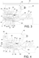
- the main state of the device is that of figures 2 And 3 : the radial splines 36 and 37 mesh with each other, the spring 54 pushes the coupling sleeve 34 rearward, and the armature 22, the low-pressure shaft 1, the shaft section 18 and the coupling sleeve 34 rotate in unison and drive the rotor 12 of the electric machine 10, which is therefore active.
- the motors 51 are requested to move the rollers 52 against the collar 44 and push it forward, which disengages the radial splines 36 and 37 and allows the armature 22 and the rotor 12 to rotate at a different speed from the low pressure shaft 1.
- the bearings 26 and 27 start moving and cause the grease to circulate through the bores 32 and 33.
- the bearing surfaces 41 and 45 keep the lubrication cavity 28 closed despite their sliding movements and the axial splines 39 and 40 continue to mesh with each other.
- the spring 54 reliably returns the coupling sleeve 34 to the usual position.
- Disassembly for maintenance or replacement of the system elements is easy to accomplish, once the conical cover 8 has been removed. It is carried out by successively removing each module of the device among the stator 11 of the electric machine 10, the journal 15, the actuator 48 and the coupling sleeve 34. The operator remains in the same position. Disassembly of the stator 11 of the electric machine 10 is first done by disassembling the first flange 14. The plug 20 is then unscrewed, the reservoir 30 emptied of its grease, and a tool introduced forward to turn the bolt 19, resting on radially internal reliefs 56, projecting inside the reservoir 30. The journal 15 is then dismantled from the end 5 of the low pressure shaft 1. The actuator 48 is then removed by dismantling the second flange 50. The coupling sleeve 43 can then also be dismantled, simply by pulling it. All movements are carried out in a straight line towards the rear.
- the reservoir 30 contains a brake 57 of the nut 19, composed of a flexible rod of which a rear end 58 is stopped against the inner wall of the shaft section 18 by the engagement of an elastic seal 65 in a groove, and of which the front end 59 comprises axial grooves 75 engaged in complementary grooves of the nut 19.
- the flexible rod is curved before turning the nut 19, in order to release it from the front end 59.
- FIG. 6 An alternative embodiment of this part of the device is shown in figure 6 .
- the brake 57 is absent, the reservoir 30 occupying the entire empty volume in the shaft section 18 is replaced by an annular reservoir 66 at the periphery of the empty volume 30.
- the nut 19 is replaced by a nut 67 and a locknut 68 locking each other.
- the nut 67 and the locknut 68 are provided with internal radial reliefs 69 that a tool 70, introduced as previously from the rear into the shaft section 18, can grip to cause tightening and loosening.
- the tool 70 passes through a volume free of grease because the reservoir 66 has larger radii, which makes it unnecessary to drain the oil in these circumstances.
- the plug 20 as well as the nut 67 and the locknut 68 do not need to have a continuous radial wall to close the empty volume 30.
- the annular reservoir 66 is here movable towards the rear if it must be extracted from the empty volume, and otherwise retained by a seal 78 housed in a groove of the shaft section 18.
- FIG. 5 illustrates that an electronic component housing 71 can be mounted on the stator armature 13 of the electric machine.
Landscapes
- Engineering & Computer Science (AREA)
- Chemical & Material Sciences (AREA)
- Combustion & Propulsion (AREA)
- Mechanical Engineering (AREA)
- General Engineering & Computer Science (AREA)
- Power Engineering (AREA)
- Motor Or Generator Frames (AREA)
- Motor Or Generator Cooling System (AREA)
Description
- L'invention présente a trait à une turbomachine, dans laquelle une machine électrique est intégrée à l'arrière.
- Cette machine électrique peut être un générateur électrique pur, ou une machine réversible pouvant aussi travailler en moteur électrique ; elle s'ajoute à la machine électrique traditionnellement placée sur une boîte d'engrenage à la périphérie de la turbomachine pour fournir à celle-ci et à d'autres équipements d'aéronefs l'énergie électrique dont ils ont besoin. Un tel exemple de turbomachine, comprenant une machine électrique intégrée à l'arrière, est décrit dans le document
FR 3 027 625 A1 - L'intégration d'une telle machine électrique à l'arrière de la turbomachine suscite plusieurs difficultés. La température y est tout d'abord très élevée, et la machine électrique doit donc être protégée thermiquement.
-
EP 3613977 A1 décrit une machine électrique à l'arrière d'une turbomachine et détachable de la turbomachine par modules, ce qui semble rendre ce document le plus proche de l'invention. -
EP 3763929 A1 décrit le montage d'une machine électrique à l'extrémité d'un arbre haute pression de turbomachine, dans lequel le rotor de la machine électrique est monté sur un bout d'arbre coulissant qui prolonge l'arbre haute pression. -
FR 3073569 A1 -
EP 3246528 A1 etEP 3708787 A1 décrivent d'autres turbomachines équipées de machines électriques. - Les contraintes d'aménagement sont fortes, puisque l'espace est réduit.
- L'équilibrage dynamique des corps tournants est fortement compliqué pour les raisons que voici. Il est tout d'abord avantageux que le rotor de la machine électrique soit entraîné par l'arbre de la turbomachine qui s'étend le plus en arrière et s'arrête devant la machine, c'est-à-dire l'arbre basse pression ; un accouplement simple pourrait alors être envisagé. Mais le rotor alourdit l'arbre basse pression, d'autant plus qu'il est placé en porte-à-faux en arrière des paliers qui le soutiennent. Ces conséquences sont d'autant plus nettes que les évolutions actuelles des moteurs d'aéronefs conduisent à une miniaturisation, c'est-à-dire à une diminution des diamètres des arbres haute et basse pressions. Il faut ajouter que le rotor de la machine électrique ne peut en réalité pas être monté directement sur l'arbre basse pression, car il doit pouvoir être découplé de lui dans certaines situations de pannes, par exemple des courts-circuits, notamment dans le cas où la machine électrique est à aimants permanents. Il faut donc ajouter un dispositif de désaccouplement entre l'arbre basse pression et le rotor de la machine électrique, et faire soutenir le rotor par des paliers autonomes. Le dispositif est alors alourdi, et les problèmes d'aménagement et de tenue aux sollicitations dynamiques risquent de devenir plus aigus. Les paliers supplémentaires et le dispositif de désaccouplement doivent eux-mêmes tenir aux chaleurs élevées qu'ils subissent.
- On voudrait enfin que la machine électrique et ses pièces associées soient facilement démontables du reste de la turbomachine, afin de permettre des remplacements aisés.
- L'invention englobe plusieurs mesures qui permettent, séparément et en combinaison, de réduire ou supprimer les difficultés évoquées ci-dessus. L'agencement obtenu à l'arrière de la turbomachine est relativement simple, compact, facilement démontable, et relativement peu perturbateur des équilibres dynamiques de l'arbre basse pression ; des échauffements excessifs sont enfin peu à craindre.
- Sous une forme générale, qui procure déjà ces avantages, l'invention est ainsi relative à une turbomachine comprenant un arbre basse pression, s'étendant selon un axe de la turbomachine qui définit un avant et un arrière ; un stator de turbomachine soutenant l'arbre basse pression par des paliers dont un palier arrière ; une machine électrique située à une partie arrière de la turbomachine, et comprenant un rotor entraîné de façon déconnectable par l'arbre basse pression et un stator fixé au stator de la turbomachine ; comprenant un tourillon de support du rotor de la machine électrique, comprenant un tronçon d'arbre fixé de manière séparable à une extrémité arrière de l'arbre basse pression en prolongeant l'arbre basse pression, une armature à laquelle le rotor de la machine électrique est fixé et qui entoure le tronçon d'arbre ; caractérisé en ce que le stator de la machine électrique entoure le rotor de la machine électrique ; et en ce que la turbomachine comprend encore au moins un palier monté entre l'armature et le tronçon d'arbre ; et un manchon mobile axialement autour de l'arbre basse pression et/ou du tronçon d'arbre (c'est-à-dire qu'il est mobile axialement autour de l'un d'eux seulement, ou des deux), lié en rotation à l'arbre basse pression et au tronçon d'arbre, et doté de moyens d'accouplement dirigés vers l'arrière et aptes à engrener avec des moyens d'accouplement complémentaires, dirigées vers l'avant, de l'armature.
- On appelle ici « arbre basse pression » un arbre associé à la rotation d'une turbine tout à l'arrière de la turbomachine, et qui s'étend donc plus en arrière que d'autres arbres éventuels comme un arbre haute pression.
- Les constituants de la machine électrique peuvent être placés dans une cavité à l'arrière de la turbomachine, dans laquelle débouche l'extrémité de l'arbre basse pression et qui est fermée à l'arrière par un capot conique. Le tourillon porteur du rotor de la turbomachine forme un ensemble unitaire qui peut être fixé facilement à l'extrémité de l'arbre basse pression, et le stator de la machine peut être fixé au stator de la turbomachine, sans presque modifier la conception des turbomachines existantes dépourvues de la machine électrique. L'allongement de l'arbre basse pression dû à l'addition du tronçon d'arbre, et le porte-à-faux du rotor, sont modérés. Le palier ou les paliers intégrés au tourillon peuvent facilement être lubrifiés par un dispositif autonome, distinct des dispositifs de lubrification consacrés aux paliers de support de l'arbre basse pression et de l'arbre haute pression, donc sans modifier encore les circuits de lubrification existants. Le manchon d'accouplement reliant de manière amovible en rotation l'arbre basse pression et le rotor de la machine électrique est compact et occupe, sans difficulté à le concevoir, un volume vide encore présent autour de l'extrémité de l'arbre basse pression et en arrière du stator de la turbomachine. Il est par ailleurs facile à commander, et n'introduit pas de perturbations dynamiques importantes. Et le démontage des différents composants (tourillon, manchon d'accouplement et stator de la machine électrique) peut être accompli facilement.
- De nombreux perfectionnements peuvent être apportés à cette conception générale. Il est tout d'abord intéressant que le palier ou les paliers soient lubrifiés à la graisse, en étant contenus dans une enceinte de lubrification close. Une lubrification dynamique, habituelle pour les turbomachines, par une circulation forcée d'huile n'est en effet pas nécessaire pour ces paliers particuliers, qui sont inactifs à l'état habituel d'entraînement du rotor de la machine électrique, dans lequel le manchon d'accouplement solidarise en rotation l'armature avec l'arbre basse pression et le tronçon d'arbre. Une rotation entre l'armature et le tronçon d'arbre existe seulement dans les conditions de pannes de la machine électrique, pendant lesquelles un désaccouplement du manchon est ordonné. Des frottements et de la chaleur sont alors produits par les paliers disposés entre le tronçon d'arbre et le rotor, mais cet état est généralement bref, et la chaleur produite est alors insuffisante pour produire des dommages importants. De tels dommages sont susceptibles de concerner seulement les paliers, qu'on peut remplacer facilement. Et la chaleur environnante, produite le service de la turbomachine, est largement absorbée par les dispositifs de refroidissement à circulation de fluide, déjà existants, qui desservent les pièces voisines du tourillon : l'échauffement qu'il subit reste modéré même en l'absence d'un dispositif de refroidissement particulier.
- Il est avantageux que l'enceinte puisse être alimentée en graisse quelles que soient les circonstances : on préconise alors que le tronçon d'arbre soit creux et contienne un réservoir de graisse qui communique à l'enceinte par au moins un perçage.
- Cette conception peut elle-même être perfectionnée. La graisse du réservoir peut contribuer à lubrifier aussi les dispositifs d'accouplement entre le manchon d'une part, l'armature, l'arbre basse pression ou le tronçon d'arbre d'autre part. L'enceinte de lubrification est alors délimitée en partie par ces pièces.
- Et comme le réservoir de graisse est à une position radiale plus proche de l'axe que les dispositifs à lubrifier, la graisse est entraînée par les forces centrifuges jusqu'à ces dispositifs.
- Les dispositifs d'accouplement peuvent être des réseaux de cannelures orientées radialement ou axialement, selon que la connexion entre les pièces qu'elles relient doit être interrompue ou maintenue pendant leurs mouvements axiaux d'un état à l'autre.
- D'après une autre disposition avantageuse quant à la facilité de l'aménagement, la turbomachine comprend encore un actionneur du manchon qui est logé axialement entre le stator de turbomachine et l'armature, et radialement entre l'armature et le manchon.
- Une conception simple et avantageuse de l'actionneur comprend au moins un galet mobile axialement et tournant librement autour d'un axe radial, apte à buter contre une collerette plane du manchon et à repousser la collerette.
- Afin de maintenir l'accouplement entre le manchon et l'armature sauf quand sa suppression est ordonnée, l'agencement comprend avantageusement un ressort engagé autour de l'arbre basse pression, et comprimé entre l'arbre basse pression et le manchon.
- Toutes ces caractéristiques ne s'accompagnent pas d'un accroissement important d'encombrement du dispositif.
- D'autres perfectionnements possibles améliorent le caractère démontable par module du dispositif associé à la machine électrique, et en particulier du tourillon porteur de son rotor. Il est tout d'abord avantageux que le tronçon d'arbre soit fixé à l'extrémité arrière de l'arbre basse pression par un écrou.
- Le démontage est alors facile si le tronçon d'arbre contient un creux, l'écrou comprend des reliefs d'accrochage par un outil qui sont saillants dans le creux, et l'écrou comprend un frein anti-rotation placé dans le creux.
- En combinant cette caractéristique à une des précédentes, d'après laquelle le tronçon d'arbre contient un réservoir de graisse, on peut avantageusement, faisant coïncider le creux avec le réservoir, le munir d'une ouverture à une extrémité arrière du tronçon d'arbre et d'un bouchon fermant à volonté à l'ouverture. Toutes ces mesures permettent d'accéder facilement à l'écrou de fixation du tourillon à l'extrémité de l'arbre basse pression pendant une campagne d'entretien, en introduisant un outil dans le creux, ou le réservoir préalablement vidé de son contenu.
- En variante, le réservoir pourrait occuper seulement une partie périphérique du volume intérieur du tronçon d'arbre, afin d'accéder plus facilement à l'écrou de fixation, par la partie centrale du volume intérieur, qui reste alors vide.
- Et la facilité de démontage est complète si le tourillon est séparable de l'arbre basse pression et du manchon en coulissant vers l'arrière, le manchon est fixé au stator de turbomachine par une première bride boulonnée accessible de l'arrière, et le stator de la machine électrique est fixée au stator de la turbomachine par une seconde bride boulonnée accessible de l'arrière.
- Pour résumer, un aspect important de l'invention est que le tourillon, le manchon, le stator de la machine électrique, et l'actionneur quand il est présent aussi à l'arrière de la turbomachine, sont formés en modules distincts et unitaires, démontables successivement de la turbomachine (et remontables de même). Leur caractère modulaire, distinct et unitaire signifie qu'ils forment des portions indépendantes du dispositif, dont chacune est apportée ou enlevée en bloc, qu'ils sont assemblés au reste de la turbomachine sans être nécessairement assemblées entre eux, et qu'ils sont remplaçables séparément.
- Les différents aspects, caractéristiques et avantages de l'invention seront maintenant décrits plus en détail au moyen de la description détaillée des figures suivantes, qui en illustrent une réalisation particulière, donnée à titre purement illustratif :
- la
Figure 1 représente schématiquement l'arrière d'une turbomachine et les différents constituants de l'invention ; - la
Figure 2 illustre plus en détail ses principaux constituants ; et - la
Figure 3 et - la
Figure 4 illustrent les deux états du dispositif ; - la
Figure 5 représente un schéma d'ensemble du dispositif et de sa disposition sur la turbine; - la
Figure 6 représente une variante de réalisation. - La description porte d'abord sur les
figures 1 et2 . La turbomachine comprend un axe central X-X s'étendant dans une direction longitudinale, entre un sens avant (à gauche des figures) et un sens arrière (à droite des figures). Seule la partie arrière de la turbomachine près de l'axe X-X est représentée, le reste de la turbomachine n'étant pas modifié par l'invention. La turbomachine comprend un arbre basse pression 1 disposé dans l'axe X-X et tournant autour de cet axe. Elle comprend un stator 2 dans lequel l'arbre basse pression 1 est soutenu par divers paliers, dont un palier arrière, qui est le plus en arrière des paliers au moyen desquels l'arbre basse pression 1 est soutenu par le stator 2. La partie visible du stator 2 est précisément un carter d'échappement de la turbomachine. Les paliers, entre autres le palier arrière, sont contenus dans des enceintes lubrifiées délimitées par le stator 2. L'arbre basse pression 1 a une extrémité 5 qui sort de l'enceinte lubrifiée arrière 4 contenant le palier arrière, à l'arrière d'un joint principal d'étanchéité 3 qui délimite l'enceinte lubrifiée arrière 4, par une ouverture circulaire du stator 2 munie d'un joint d'étanchéité à labyrinthe 6 qui complète le joint principal d'étanchéité 3. Un circuit de lubrification 7, seulement schématisé, passe par l'enceinte de lubrification arrière 4 et apporte de l'huile au palier arrière 3, afin aussi d'évacuer la chaleur qu'il produit. Le palier arrière est représenté à lafigure 5 , à la référence 73. Il est immédiatement en avant du joint principal d'étanchéité 3. L'enceinte lubrifiée arrière 4 est fermée à l'avant par une autre partie 74 du stator 2 et un autre ensemble composé d'un palier 64 et d'un joint d'étanchéité 77 reliant l'arbre basse pression 1 à ladite autre partie 74. - La turbomachine a un volume vide en arrière du stator 2 près de l'axe X-X, dans le cône arrière de la turbine, et l'extrémité 5 débouche hors du stator 2 à cet endroit. Le volume correspondant peut être isolé de l'extérieur par un capot conique 8 pour former une cavité arrière 9 qui peut recevoir divers équipements, comme une machine électrique 10 comprenant un stator 11 et un rotor 12 entouré par le stator 11. Le stator 11 consiste ici en des enroulements électriques et le rotor 12 en des aimants permanents, mais d'autres dispositions de la machine électrique seraient possibles. Le stator 11 comporte une armature de stator 13 rigide, fixée au stator 2 de la turbomachine par une première bride 14. Le rotor 12 est porté par une des pièces principales de l'invention, dite tourillon 15, qui sera décrite en détail et qui est portée par l'extrémité 5 de l'arbre basse pression 1. Un circuit de refroidissement 16, seulement ébauché lui aussi, passe par le stator 2 de la turbomachine et évacue la chaleur produite aux alentours du stator 11 de la machine électrique. Et la cavité arrière 9 est protégée de la chaleur produite autour d'elle par les gaz d'échappement de la turbomachine, par des couches isolantes 17 en doublure intérieure du capot conique 8.
- La description porte maintenant, en recourant surtout à la
figure 2 , sur le tourillon 15. Il comprend d'abord un tronçon d'arbre 18, qui prolonge d'une courte étendue l'arbre basse pression 1 à l'arrière de son extrémité 5, et qui est fixé à l'extrémité 5, de manière coaxiale à elle, par un écrou 19. Le tronçon d'arbre 18 est creux, en forme de manchon évidé autour de l'axe X-X, mais clos à l'arrière par un bouchon 20 vissé autour de son extrémité. L'écrou 19 est logé (on se reportera aussi auxfigures 3 et 4 pour ces détails de description) dans le creux du tronçon d'arbre 18, est vissé dans un taraudage 21 de l'extrémité 5, repousse un épaulement 60 du tronçon d'arbre 18 en le faisant buter contre la face arrière de l'extrémité 5, Une manchette 61 du tronçon d'arbre 18, qui s'étend vers l'avant, s'appuie sur la face extérieure de l'extrémité 5 et assure la coaxialité de l'extrémité 5 et du tronçon d'arbre 18. - Une armature 22, porteuse du rotor 12 de la machine électrique 10, est disposée autour du tronçon d'arbre 20. Elle comporte un manchon intérieur 23, un manchon extérieur 24 et une paire de brides 25, respectivement solidaires des manchons, à peu près planes et d'orientation radiale, et boulonnées entre elles. L'armature 22 forme donc une structure rigide. Un palier de rotation, consistant ici en un roulement à billes 26 à l'avant et un roulement à rouleaux 27 à l'arrière, est disposé radialement entre le manchon intérieur 23 et le tronçon d'arbre 18 pour les solidariser, tout en permettant leur rotation. Les positions des roulements 26 et 27 dans la direction de l'axe X-X, par rapport au tronçon d'arbre 18 et au manchon intérieur 23, sont garanties par des systèmes de butées et entretoises, visibles sur les dessins. Une enceinte de lubrification 28 est formée entre le tronçon d'arbre 18 et le manchon intérieur 23. Elle englobe les roulements 26 et 27 ; elle est close à l'arrière par un joint d'étanchéité 29 placé entre le manchon intérieur 23 et la paroi cylindrique du bouchon 20 ; et elle communique avec un réservoir 30 qui est le volume creux englobé par le tronçon d'arbre 18 qui s'étend, d'arrière en avant, du bouchon 20 à l'extrémité 5. La communication se fait par des perçages 31 et 32 menant directement aux roulements 26 et 27 ; un perçage principal 33 relie toutefois le réservoir 30 à une autre partie 76 de l'enceinte de lubrification 28, située plus en avant et sur laquelle on reviendra.
- Un autre élément important du dispositif est un manchon d'accouplement 34 qui assure la commutation entre deux états du dispositif. Il comprend une partie principale 35, plane et radialement médiane, pourvue de cannelures radiales 36 dirigées vers l'arrière, réparties sur sa circonférence, et qui, dans la position habituelle, engrènent avec des cannelures radiales 37 correspondantes, situées à l'avant du manchon intérieur 23 et dirigées vers l'avant. Le manchon d'accouplement 34 comprend encore une partie radialement intérieure 38 globalement cylindrique, pourvue de cannelures axiales 39 à sa face dirigée vers l'intérieur, et qui engrènent avec des cannelures axiales 40 situées sur la manchette 61. La partie radialement intérieure 38 comporte une portée avant 41 qui glisse sur la manchette 61; un joint 42, disposé à cet endroit, limite la cavité de lubrification 28 à l'avant. On notera enfin d'autres cannelures axiales 62 et 63, appartenant respectivement à la manchette 61 et à l'extrémité 5, engrenant les unes dans les autres et qui maintiennent le tronçon d'arbre 18 et l'arbre basse pression 1 solidaires en rotation.
- Le manchon d'accouplement 34 comprend enfin une partie radialement extérieure 43, globalement cylindrique, qui comprend à l'avant un évasement 44, proche du stator 2 de la turbomachine mais séparé de lui, et à l'arrière une portée 45 qui glisse sur la face extérieure de l'avant du manchon intérieur 23 ; des joints 46, placés à cet endroit, achèvent d'isoler la cavité de lubrification 28 à l'égard de l'extérieur ; la cavité de lubrification 28 englobe donc aussi les cannelures radiales 36 et 37 et axiales 39 et 40, que la graisse lubrifie.
- Un actionneur 48 est disposé dans le volume compris radialement entre le manchon d'accouplement 34, plus précisément sa partie radialement extérieure 43, et le manchon extérieur 24 de l'armature 22, et il est compris axialement entre le stator de turbomachine 2 à l'avant et les brides 25 à l'arrière. L'actionneur 48 est muni d'un support 49 retenu sur le stator 2 de turbomachine par une deuxième bride 50 concentrique à la première bride 14 et entourée par elle. Il comprend des moteurs 51, tels que des vérins électriques, aptes à déplacer vers l'avant des galets 52 tournants autour d'axes radiaux 53 repoussés par les moteurs 51. L'alimentation des moteurs 51 en électricité ou en fluide peut s'effectuer par des fils électriques ou des câbles passant le long du stator 2 de la turbomachine.
- Un ressort 54 hélicoïdal est comprimé entre la partie principale 35 du manchon d'accouplement 34 à l'arrière, et une manchette 55, appartenant à l'arbre basse pression 1 et à laquelle appartient une moitié du joint à labyrinthe 6, à l'avant. La portée avant 41 comporte une saillie extérieure annulaire 72 ou un joint (référencé aux
figures 3 et 4 ) qui restreint la section de fuites de gaz que la portée avant 41 fait avec ladite manchette 55, pour accroître l'étanchéité de l'enceinte lubrifiée arrière 4. - L'état principal du dispositif est celui des
figures 2 et3 : les cannelures radiales 36 et 37 engrènent les unes dans les autres, le ressort 54 repousse le manchon d'accouplement 34 vers l'arrière, et l'armature 22, l'arbre basse pression 1, le tronçon d'arbre 18 et le manchon d'accouplement 34 tournent à l'unisson et entraînent le rotor 12 de la machine électrique 10, qui est donc active. - Si par contre (ceci est représenté à la
figure 4 ) un désaccouplement du rotor 12 et de l'arbre basse pression 1 doit être commandé au moyen de l'actionneur 48 : les moteurs 51 sont sollicités pour déplacer les galets 52 contre la collerette 44 et la repousser vers l'avant, ce qui disjoint les cannelures radiales 36 et 37 et permet à l'armature 22 et au rotor 12 de tourner à une vitesse différente de l'arbre basse pression 1. Les roulements 26 et 27 se mettent en mouvement et suscitent une circulation de la graisse à travers les perçages 32 et 33. Les portées 41 et 45 maintiennent la fermeture de la cavité de lubrification 28 malgré leurs mouvements coulissants et les cannelures axiales 39 et 40 continuent à engrener les unes dans les autres. Quand les moteurs 51 sont relâchés, le ressort 54 ramène sûrement le manchon d'accouplement 34 à la position habituelle. - Le démontage à des fins d'entretien ou de remplacement des éléments du système est facile à accomplir, une fois que le capot conique 8 a été retiré. Il s'effectue en enlevant successivement chaque module du dispositif parmi le stator 11 de la machine électrique 10, le tourillon 15, l'actionneur 48 et le manchon d'accouplement 34. L'opérateur reste à la même position. Le démontage du stator 11 de la machine électrique 10 est tout d'abord fait en démontant la première bride 14. Le bouchon 20 est ensuite dévissé, le réservoir 30 vidé de sa graisse, et un outil introduit vers l'avant pour tourner le boulon 19, en s'appuyant sur des reliefs radialement intérieurs 56, saillant à l'intérieur du réservoir 30. Le tourillon 15 est alors démonté de l'extrémité 5 de l'arbre basse pression 1. L'actionneur 48 est ensuite retiré en démontant la deuxième bride 50. Le manchon d'accouplement 43 est alors démontable lui aussi, simplement en le tirant. Tous les mouvements s'effectuent en ligne droite vers l'arrière.
- Le réservoir 30 contient un frein 57 de l'écrou 19, composé d'une tige flexible dont une extrémité arrière 58 est arrêtée contre la paroi intérieure du tronçon d'arbre 18 par l'engagement d'un joint élastique 65 dans une gorge, et dont l'extrémité avant 59 comprend des cannelures axiales 75 engagée dans des cannelures complémentaires de l'écrou 19. La tige flexible est courbée avant de tourner l'écrou 19, afin de le dégager de l'extrémité avant 59.
- Une variante de réalisation de cette partie du dispositif est représentée à la
figure 6 . Le frein 57 est absent, le réservoir 30 occupant tout le volume vide dans le tronçon d'arbre 18 est remplacé par un réservoir annulaire 66 à la périphérie du volume vide 30. L'écrou 19 est remplacé par un écrou 67 et un contre-écrou 68 se bloquant mutuellement. L'écrou 67 et le contre-écrou 68 sont munis de reliefs radiaux intérieurs 69 qu'un outil 70, introduit comme précédemment par l'arrière dans le tronçon d'arbre 18, peut agripper pour provoquer le serrage et le desserrage. Toutefois, l'outil 70 passe dans un volume libre de graisse car le réservoir 66 est à des rayons plus grands, ce qui dispense de faire une vidange dans ces circonstances. Dans cette variante, le bouchon 20 ainsi que l'écrou 67 et le contre-écrou 68 n'ont pas besoin d'avoir une paroi radiale continue pour fermer le volume vide 30. Le réservoir annulaire 66 est ici mobile vers l'arrière s'il doit être extrait du volume vide, et retenu sinon par un joint 78 logé dans une gorge du tronçon d'arbre 18. - La
figure 5 illustre qu'un boîtier de composants électroniques 71 peut être monté sur l'armature de stator 13 de la machine électrique.
Claims (13)
- Turbomachine, comprenant un arbre basse pression (1) s'étendant selon un axe (X-X) de la turbomachine qui définit un avant et un arrière ; un stator (2) de turbomachine soutenant l'arbre basse pression par des paliers dont un palier arrière (73) ; une machine électrique (10) située à une partie arrière de la turbomachine, et comprenant un rotor (12) entraîné de façon déconnectable par l'arbre basse pression (1), et un stator (11) fixé au stator (2) de la turbomachine ; comprenant un tourillon (15) de support du rotor (12) de la machine électrique, le tourillon comprenant un tronçon d'arbre (18) fixé de manière séparable à une extrémité (5) arrière de l'arbre basse pression en prolongeant l'arbre basse pression, une armature (22) à laquelle le rotor de la machine électrique est fixé et qui entoure le tronçon d'arbre (18), caractérisée en ce que le stator (11) de la machine électrique entoure le rotor (12) de la machine électrique ; et la turbomachine comprend encore au moins un palier (26, 27) monté entre l'armature et le tronçon d'arbre ; et un manchon (34) mobile axialement autour de l'arbre basse pression (1) et/ou du tronçon d'arbre (18), lié en rotation à l'arbre basse pression et au tronçon d'arbre, et doté de moyens d'accouplement (36) dirigés vers l'arrière et aptes à engrener avec des moyens d'accouplement complémentaires (37), dirigées vers l'avant, de l'armature (22).
- Turbomachine selon la revendication 1, caractérisée en ce que l'au moins un palier (26, 27) est lubrifié à la graisse et est contenu dans une enceinte de lubrification (28) close.
- Turbomachine selon la revendication 2, caractérisée en ce que le tronçon d'arbre (18) est creux et contient un réservoir (30) de graisse qui communique à l'enceinte de lubrification par au moins un perçage (31, 32, 33).
- Turbomachine selon l'une quelconque des revendications 1 à 3, caractérisée en ce que les moyens d'accouplement (36, 37) sont des réseaux de cannelures radiales.
- Turbomachine selon l'une quelconque des revendications 1 à 4, caractérisée en ce que le manchon est lié au tronçon d'arbre (18) par des réseaux de cannelures axiales (39, 40).
- Turbomachine selon les revendications 2, 4 et 5, caractérisée en ce que l'enceinte (28) de lubrification contient aussi les cannelures radiales et axiales.
- Turbomachine selon l'une quelconque des revendications 1 à 6, caractérisée en ce qu'elle comprend un actionneur (48) du manchon (34), qui est logé axialement entre le stator (2) de turbomachine et l'armature (22), et radialement entre l'armature (22) et le manchon (34).
- Turbomachine selon la revendication 7, caractérisée en ce que l'actionneur comprend au moins un galet (52) mobile axialement et tournant librement autour d'un axe radial (53), apte à buter contre une collerette (44) plane du manchon et à repousser la collerette.
- Turbomachine selon l'une quelconque des revendications 1 à 8, caractérisée en ce qu'elle comprend un ressort (54) engagé autour de l'arbre basse pression, et comprimé entre l'arbre basse pression (1) et le manchon (34).
- Turbomachine selon l'une quelconque des revendications 1 à 9, caractérisée en ce que le tronçon d'arbre est fixé à l'extrémité (5) arrière de l'arbre basse pression par un écrou (19).
- Turbomachine selon l'une quelconque des revendications 1 à 10, caractérisée en ce que le tourillon (15) est séparable de l'arbre basse pression et du manchon en coulissant vers l'arrière, le manchon (34) est fixé au stator (2) de turbomachine par une première bride (49) boulonnée accessible de l'arrière, et le stator (11) de la machine électrique est fixée au stator (2) de la turbomachine par une seconde bride (14) boulonnée accessible de l'arrière.
- Turbomachine selon l'une quelconque des revendications précédentes, caractérisée en ce que le tourillon (15), le manchon (34), et le stator (11) de la machine électrique sont formés en modules distincts et unitaires, démontables successivement de la turbomachine.
- Turbomachine selon les revendications 7 et 12, caractérisée en ce que l'actionneur (48) est un autre module unitaire, distinct desdits modules et démontable séparément d'eux de la turbomachine.
Applications Claiming Priority (2)
| Application Number | Priority Date | Filing Date | Title |
|---|---|---|---|
| FR2105516A FR3123375B1 (fr) | 2021-05-27 | 2021-05-27 | Turbomachine comprenant une machine électrique intégrée à l’arrière |
| PCT/FR2022/050970 WO2022248798A1 (fr) | 2021-05-27 | 2022-05-23 | Turbomachine comprenant une machine électrique intégrée à l'arrière |
Publications (2)
| Publication Number | Publication Date |
|---|---|
| EP4348012A1 EP4348012A1 (fr) | 2024-04-10 |
| EP4348012B1 true EP4348012B1 (fr) | 2024-11-27 |
Family
ID=76523178
Family Applications (1)
| Application Number | Title | Priority Date | Filing Date |
|---|---|---|---|
| EP22731746.8A Active EP4348012B1 (fr) | 2021-05-27 | 2022-05-23 | Turbomachine comprenant une machine électrique intégrée à l'arrière |
Country Status (5)
| Country | Link |
|---|---|
| US (1) | US12152538B2 (fr) |
| EP (1) | EP4348012B1 (fr) |
| CN (1) | CN117425765A (fr) |
| FR (1) | FR3123375B1 (fr) |
| WO (1) | WO2022248798A1 (fr) |
Families Citing this family (10)
| Publication number | Priority date | Publication date | Assignee | Title |
|---|---|---|---|---|
| US12173650B2 (en) * | 2022-10-25 | 2024-12-24 | Ge Infrastructure Technology Llc | Combined cycle power plant having reduced parasitic pumping losses |
| US12188369B2 (en) | 2023-02-08 | 2025-01-07 | Hamilton Sundstrand Corporation | Aircraft tail cone mounted generators |
| FR3151635B1 (fr) * | 2023-07-26 | 2025-06-20 | Safran Aircraft Engines | Ensemble pour turbomachine d’aeronef, comportant un systeme de blocage axial d’un bouchon relativement a un arbre creux de la turbomachine |
| FR3154260A1 (fr) * | 2023-10-16 | 2025-04-18 | Safran Aircraft Engines | Support de palier agencé pour porter une machine électrique sans engendrer de modes de vibration supplémentaires |
| US12372010B1 (en) * | 2024-01-26 | 2025-07-29 | Rtx Corporation | Passive ventilation system for tail cone zone |
| FR3159634A1 (fr) | 2024-02-28 | 2025-08-29 | Safran Aircraft Engines | Ensemble comportant un arbre et une machine electrique pour une turbomachine d’aeronef, et procede de montage de cet ensemble |
| FR3161246A1 (fr) | 2024-04-11 | 2025-10-17 | Safran Aircraft Engines | Turbomachine equipee d’une machine electrique agencee dans son enceinte dediee et d’un systeme de lubrification de l’enceinte dediee |
| FR3161247A1 (fr) * | 2024-04-11 | 2025-10-17 | Safran Aircraft Engines | Turbomachine equipee d’une machine electrique dans son enceinte de lubrification |
| FR3161249A1 (fr) * | 2024-04-11 | 2025-10-17 | Safran Aircraft Engines | Turbomachine equipee d’une machine electrique deconnectable et d’un organe d’appui pour sa deconnexion |
| CN119801672B (zh) * | 2024-11-11 | 2025-12-26 | 中国航发沈阳发动机研究所 | 一种双级低压涡轮盘轴连接结构 |
Citations (1)
| Publication number | Priority date | Publication date | Assignee | Title |
|---|---|---|---|---|
| FR3027625A1 (fr) * | 2014-10-27 | 2016-04-29 | Snecma | Turbomachine comprenant un generateur de courant electrique permettant l'injection d'huile depuis l'interieur d'un arbre de turbine |
Family Cites Families (12)
| Publication number | Priority date | Publication date | Assignee | Title |
|---|---|---|---|---|
| DE1928660A1 (de) * | 1969-06-06 | 1970-12-17 | Motoren Turbinen Union | Zweiwellengasturbinentriebwerk |
| US20060137355A1 (en) * | 2004-12-27 | 2006-06-29 | Pratt & Whitney Canada Corp. | Fan driven emergency generator |
| US8237298B2 (en) * | 2008-12-22 | 2012-08-07 | Hamilton Sundstrand Corporation | Generator coupling for use with gas turbine engine |
| US8935912B2 (en) * | 2011-12-09 | 2015-01-20 | United Technologies Corporation | Gas turbine engine with variable overall pressure ratio |
| EP3246528B1 (fr) | 2016-05-18 | 2020-10-28 | Rolls-Royce Corporation | Générateur basse pression ayant un ensemble électrique pour moteur à turbine à gaz |
| US10487839B2 (en) * | 2016-08-22 | 2019-11-26 | General Electric Company | Embedded electric machine |
| US11371379B2 (en) * | 2017-08-22 | 2022-06-28 | General Electric Company | Turbomachine with alternatingly spaced turbine rotor blades |
| FR3073569B1 (fr) * | 2017-11-15 | 2020-02-07 | Safran Helicopter Engines | Turbopropulseur comportant un mecanisme de reduction integrant un dispositif de generation de courant |
| GB2572427B (en) * | 2018-03-29 | 2023-01-11 | Safran Electrical & Power | A generator having a disconnect mechanism |
| US11156128B2 (en) | 2018-08-22 | 2021-10-26 | General Electric Company | Embedded electric machine |
| US11242156B2 (en) | 2019-03-15 | 2022-02-08 | Hamilton Sundstrand Corporation | Plug in fluid cooled electrical connections for tail cone mounted generator |
| GB201910009D0 (en) * | 2019-07-12 | 2019-08-28 | Rolls Royce Plc | Gas turbine engine electrical generator |
-
2021
- 2021-05-27 FR FR2105516A patent/FR3123375B1/fr active Active
-
2022
- 2022-05-23 CN CN202280034323.5A patent/CN117425765A/zh active Pending
- 2022-05-23 EP EP22731746.8A patent/EP4348012B1/fr active Active
- 2022-05-23 US US18/561,811 patent/US12152538B2/en active Active
- 2022-05-23 WO PCT/FR2022/050970 patent/WO2022248798A1/fr not_active Ceased
Patent Citations (1)
| Publication number | Priority date | Publication date | Assignee | Title |
|---|---|---|---|---|
| FR3027625A1 (fr) * | 2014-10-27 | 2016-04-29 | Snecma | Turbomachine comprenant un generateur de courant electrique permettant l'injection d'huile depuis l'interieur d'un arbre de turbine |
Also Published As
| Publication number | Publication date |
|---|---|
| US20240229723A1 (en) | 2024-07-11 |
| WO2022248798A1 (fr) | 2022-12-01 |
| US12152538B2 (en) | 2024-11-26 |
| FR3123375A1 (fr) | 2022-12-02 |
| EP4348012A1 (fr) | 2024-04-10 |
| CN117425765A (zh) | 2024-01-19 |
| FR3123375B1 (fr) | 2023-05-12 |
Similar Documents
| Publication | Publication Date | Title |
|---|---|---|
| EP4348012A1 (fr) | Turbomachine comprenant une machine électrique intégrée à l'arrière | |
| CA2442949C (fr) | Palier a roulement amorti a l`huile | |
| CA2606069C (fr) | Arbre d'entrainement de boitier a engrenages de machines auxiliaires d'un turboreacteur; machine auxiliaire supplementaire modulaire | |
| EP1375941B1 (fr) | Palier à roulement étanche amorti à l'huile | |
| CA2874707C (fr) | Palier a moyen de lubrification et systeme pour changer le pas des pales d'une helice de turbopropulseur d'aeronef, equipe dudit palier | |
| CA2938385A1 (fr) | Turbomachine equipee d'un groupe de lubrification | |
| FR2911917A1 (fr) | Architecture distribuee de demarreur-generateur de turbine a gaz | |
| EP0494007A1 (fr) | Turbopompe à gavage intégré en flux unique | |
| WO2010119115A1 (fr) | Moteur a turbine a gaz a double corps pourvu d ' un palier inter-arbres | |
| FR3020409A1 (fr) | Assemblage pour turbomachine d'aeronef, comprenant un boitier de prelevement de puissance mecanique a acces simplifie | |
| EP4343133B1 (fr) | Boitier d'accessoires compact comportant une machine electrique integree | |
| FR3124541A1 (fr) | Turbomachine comprenant une machine électrique à une extrémité arrière de turbine | |
| WO2015140476A1 (fr) | Relais d'accessoires pour moteur à turbine à gaz | |
| WO2014013201A1 (fr) | Dispostif de transfert thermique entre une canalisation de lubrification et une canalisation hydraulique de commande de verin de calage de pales de turbomachine | |
| EP3735379B1 (fr) | Turbopropulseur comprenant une generatrice d'electricite integree | |
| EP3601747B1 (fr) | Relais d'accessoires pour moteur a turbine a gaz | |
| FR3084919A1 (fr) | Turbomachine a etages multiples | |
| EP2715104A2 (fr) | Dispositif de transmission hydraulique et demarreur hydraulique compact | |
| EP4127417B1 (fr) | Ensemble pour turbomachine d'aéronef comportant un système amelioré de lubrification d'un réducteur d'entrainement de soufflante | |
| FR3087512A1 (fr) | Dispositif amortisseur | |
| WO2025215317A1 (fr) | Turbomachine equipee d'une machine electrique dans son enceinte de lubrification | |
| WO2025215318A1 (fr) | Turbomachine equipee d'une machine electrique agencee dans son enceinte dediee et d'un systeme de lubrification de l'enceinte dediee | |
| WO2025215316A1 (fr) | Turbomachine equipee d'une machine electrique deconnectable et d'un organe d'appui pour sa deconnexion | |
| EP4658917A1 (fr) | Assemblage pour ensemble propulsif d'aeronef avec accouplement debrayable de deux arbres par un manchon d'accouplement a actionnement par fluide pressurise | |
| FR3167667A1 (fr) | Turbomachine equipee d’une machine electrique et de moyens d’accouplement entre un arbre de la turbomachine et un arbre relie a la machine electrique |
Legal Events
| Date | Code | Title | Description |
|---|---|---|---|
| STAA | Information on the status of an ep patent application or granted ep patent |
Free format text: STATUS: UNKNOWN |
|
| STAA | Information on the status of an ep patent application or granted ep patent |
Free format text: STATUS: THE INTERNATIONAL PUBLICATION HAS BEEN MADE |
|
| PUAI | Public reference made under article 153(3) epc to a published international application that has entered the european phase |
Free format text: ORIGINAL CODE: 0009012 |
|
| STAA | Information on the status of an ep patent application or granted ep patent |
Free format text: STATUS: REQUEST FOR EXAMINATION WAS MADE |
|
| 17P | Request for examination filed |
Effective date: 20231106 |
|
| AK | Designated contracting states |
Kind code of ref document: A1 Designated state(s): AL AT BE BG CH CY CZ DE DK EE ES FI FR GB GR HR HU IE IS IT LI LT LU LV MC MK MT NL NO PL PT RO RS SE SI SK SM TR |
|
| DAV | Request for validation of the european patent (deleted) | ||
| DAX | Request for extension of the european patent (deleted) | ||
| GRAP | Despatch of communication of intention to grant a patent |
Free format text: ORIGINAL CODE: EPIDOSNIGR1 |
|
| STAA | Information on the status of an ep patent application or granted ep patent |
Free format text: STATUS: GRANT OF PATENT IS INTENDED |
|
| GRAS | Grant fee paid |
Free format text: ORIGINAL CODE: EPIDOSNIGR3 |
|
| GRAA | (expected) grant |
Free format text: ORIGINAL CODE: 0009210 |
|
| STAA | Information on the status of an ep patent application or granted ep patent |
Free format text: STATUS: THE PATENT HAS BEEN GRANTED |
|
| INTG | Intention to grant announced |
Effective date: 20240926 |
|
| AK | Designated contracting states |
Kind code of ref document: B1 Designated state(s): AL AT BE BG CH CY CZ DE DK EE ES FI FR GB GR HR HU IE IS IT LI LT LU LV MC MK MT NL NO PL PT RO RS SE SI SK SM TR |
|
| REG | Reference to a national code |
Ref country code: GB Ref legal event code: FG4D Free format text: NOT ENGLISH |
|
| REG | Reference to a national code |
Ref country code: CH Ref legal event code: EP |
|
| REG | Reference to a national code |
Ref country code: IE Ref legal event code: FG4D Free format text: LANGUAGE OF EP DOCUMENT: FRENCH |
|
| REG | Reference to a national code |
Ref country code: DE Ref legal event code: R096 Ref document number: 602022008231 Country of ref document: DE |
|
| REG | Reference to a national code |
Ref country code: LT Ref legal event code: MG9D |
|
| REG | Reference to a national code |
Ref country code: NL Ref legal event code: MP Effective date: 20241127 |
|
| PG25 | Lapsed in a contracting state [announced via postgrant information from national office to epo] |
Ref country code: IS Free format text: LAPSE BECAUSE OF FAILURE TO SUBMIT A TRANSLATION OF THE DESCRIPTION OR TO PAY THE FEE WITHIN THE PRESCRIBED TIME-LIMIT Effective date: 20250327 Ref country code: HR Free format text: LAPSE BECAUSE OF FAILURE TO SUBMIT A TRANSLATION OF THE DESCRIPTION OR TO PAY THE FEE WITHIN THE PRESCRIBED TIME-LIMIT Effective date: 20241127 Ref country code: PT Free format text: LAPSE BECAUSE OF FAILURE TO SUBMIT A TRANSLATION OF THE DESCRIPTION OR TO PAY THE FEE WITHIN THE PRESCRIBED TIME-LIMIT Effective date: 20250327 |
|
| PG25 | Lapsed in a contracting state [announced via postgrant information from national office to epo] |
Ref country code: FI Free format text: LAPSE BECAUSE OF FAILURE TO SUBMIT A TRANSLATION OF THE DESCRIPTION OR TO PAY THE FEE WITHIN THE PRESCRIBED TIME-LIMIT Effective date: 20241127 Ref country code: NL Free format text: LAPSE BECAUSE OF FAILURE TO SUBMIT A TRANSLATION OF THE DESCRIPTION OR TO PAY THE FEE WITHIN THE PRESCRIBED TIME-LIMIT Effective date: 20241127 |
|
| REG | Reference to a national code |
Ref country code: AT Ref legal event code: MK05 Ref document number: 1745889 Country of ref document: AT Kind code of ref document: T Effective date: 20241127 |
|
| PG25 | Lapsed in a contracting state [announced via postgrant information from national office to epo] |
Ref country code: BG Free format text: LAPSE BECAUSE OF FAILURE TO SUBMIT A TRANSLATION OF THE DESCRIPTION OR TO PAY THE FEE WITHIN THE PRESCRIBED TIME-LIMIT Effective date: 20241127 |
|
| PG25 | Lapsed in a contracting state [announced via postgrant information from national office to epo] |
Ref country code: ES Free format text: LAPSE BECAUSE OF FAILURE TO SUBMIT A TRANSLATION OF THE DESCRIPTION OR TO PAY THE FEE WITHIN THE PRESCRIBED TIME-LIMIT Effective date: 20241127 |
|
| PG25 | Lapsed in a contracting state [announced via postgrant information from national office to epo] |
Ref country code: NO Free format text: LAPSE BECAUSE OF FAILURE TO SUBMIT A TRANSLATION OF THE DESCRIPTION OR TO PAY THE FEE WITHIN THE PRESCRIBED TIME-LIMIT Effective date: 20250227 |
|
| PG25 | Lapsed in a contracting state [announced via postgrant information from national office to epo] |
Ref country code: GR Free format text: LAPSE BECAUSE OF FAILURE TO SUBMIT A TRANSLATION OF THE DESCRIPTION OR TO PAY THE FEE WITHIN THE PRESCRIBED TIME-LIMIT Effective date: 20250228 Ref country code: AT Free format text: LAPSE BECAUSE OF FAILURE TO SUBMIT A TRANSLATION OF THE DESCRIPTION OR TO PAY THE FEE WITHIN THE PRESCRIBED TIME-LIMIT Effective date: 20241127 Ref country code: LV Free format text: LAPSE BECAUSE OF FAILURE TO SUBMIT A TRANSLATION OF THE DESCRIPTION OR TO PAY THE FEE WITHIN THE PRESCRIBED TIME-LIMIT Effective date: 20241127 |
|
| PG25 | Lapsed in a contracting state [announced via postgrant information from national office to epo] |
Ref country code: PL Free format text: LAPSE BECAUSE OF FAILURE TO SUBMIT A TRANSLATION OF THE DESCRIPTION OR TO PAY THE FEE WITHIN THE PRESCRIBED TIME-LIMIT Effective date: 20241127 |
|
| PG25 | Lapsed in a contracting state [announced via postgrant information from national office to epo] |
Ref country code: RS Free format text: LAPSE BECAUSE OF FAILURE TO SUBMIT A TRANSLATION OF THE DESCRIPTION OR TO PAY THE FEE WITHIN THE PRESCRIBED TIME-LIMIT Effective date: 20250227 |
|
| PG25 | Lapsed in a contracting state [announced via postgrant information from national office to epo] |
Ref country code: SM Free format text: LAPSE BECAUSE OF FAILURE TO SUBMIT A TRANSLATION OF THE DESCRIPTION OR TO PAY THE FEE WITHIN THE PRESCRIBED TIME-LIMIT Effective date: 20241127 |
|
| PGFP | Annual fee paid to national office [announced via postgrant information from national office to epo] |
Ref country code: DE Payment date: 20250519 Year of fee payment: 4 |
|
| PG25 | Lapsed in a contracting state [announced via postgrant information from national office to epo] |
Ref country code: DK Free format text: LAPSE BECAUSE OF FAILURE TO SUBMIT A TRANSLATION OF THE DESCRIPTION OR TO PAY THE FEE WITHIN THE PRESCRIBED TIME-LIMIT Effective date: 20241127 |
|
| PG25 | Lapsed in a contracting state [announced via postgrant information from national office to epo] |
Ref country code: EE Free format text: LAPSE BECAUSE OF FAILURE TO SUBMIT A TRANSLATION OF THE DESCRIPTION OR TO PAY THE FEE WITHIN THE PRESCRIBED TIME-LIMIT Effective date: 20241127 |
|
| PGFP | Annual fee paid to national office [announced via postgrant information from national office to epo] |
Ref country code: FR Payment date: 20250526 Year of fee payment: 4 |
|
| PG25 | Lapsed in a contracting state [announced via postgrant information from national office to epo] |
Ref country code: RO Free format text: LAPSE BECAUSE OF FAILURE TO SUBMIT A TRANSLATION OF THE DESCRIPTION OR TO PAY THE FEE WITHIN THE PRESCRIBED TIME-LIMIT Effective date: 20241127 |
|
| PG25 | Lapsed in a contracting state [announced via postgrant information from national office to epo] |
Ref country code: SK Free format text: LAPSE BECAUSE OF FAILURE TO SUBMIT A TRANSLATION OF THE DESCRIPTION OR TO PAY THE FEE WITHIN THE PRESCRIBED TIME-LIMIT Effective date: 20241127 |
|
| PG25 | Lapsed in a contracting state [announced via postgrant information from national office to epo] |
Ref country code: CZ Free format text: LAPSE BECAUSE OF FAILURE TO SUBMIT A TRANSLATION OF THE DESCRIPTION OR TO PAY THE FEE WITHIN THE PRESCRIBED TIME-LIMIT Effective date: 20241127 |
|
| PG25 | Lapsed in a contracting state [announced via postgrant information from national office to epo] |
Ref country code: IT Free format text: LAPSE BECAUSE OF FAILURE TO SUBMIT A TRANSLATION OF THE DESCRIPTION OR TO PAY THE FEE WITHIN THE PRESCRIBED TIME-LIMIT Effective date: 20241127 |
|
| REG | Reference to a national code |
Ref country code: DE Ref legal event code: R097 Ref document number: 602022008231 Country of ref document: DE |
|
| PG25 | Lapsed in a contracting state [announced via postgrant information from national office to epo] |
Ref country code: SE Free format text: LAPSE BECAUSE OF FAILURE TO SUBMIT A TRANSLATION OF THE DESCRIPTION OR TO PAY THE FEE WITHIN THE PRESCRIBED TIME-LIMIT Effective date: 20241127 |
|
| PLBE | No opposition filed within time limit |
Free format text: ORIGINAL CODE: 0009261 |
|
| STAA | Information on the status of an ep patent application or granted ep patent |
Free format text: STATUS: NO OPPOSITION FILED WITHIN TIME LIMIT |
|
| REG | Reference to a national code |
Ref country code: CH Ref legal event code: L10 Free format text: ST27 STATUS EVENT CODE: U-0-0-L10-L00 (AS PROVIDED BY THE NATIONAL OFFICE) Effective date: 20251008 |
|
| 26N | No opposition filed |
Effective date: 20250828 |
|
| REG | Reference to a national code |
Ref country code: CH Ref legal event code: H13 Free format text: ST27 STATUS EVENT CODE: U-0-0-H10-H13 (AS PROVIDED BY THE NATIONAL OFFICE) Effective date: 20251223 |
|
| PG25 | Lapsed in a contracting state [announced via postgrant information from national office to epo] |
Ref country code: LU Free format text: LAPSE BECAUSE OF NON-PAYMENT OF DUE FEES Effective date: 20250523 |
|
| PG25 | Lapsed in a contracting state [announced via postgrant information from national office to epo] |
Ref country code: CH Free format text: LAPSE BECAUSE OF NON-PAYMENT OF DUE FEES Effective date: 20250531 |
|
| REG | Reference to a national code |
Ref country code: BE Ref legal event code: MM Effective date: 20250531 |
|
| PG25 | Lapsed in a contracting state [announced via postgrant information from national office to epo] |
Ref country code: MC Free format text: LAPSE BECAUSE OF FAILURE TO SUBMIT A TRANSLATION OF THE DESCRIPTION OR TO PAY THE FEE WITHIN THE PRESCRIBED TIME-LIMIT Effective date: 20241127 |
|
| PG25 | Lapsed in a contracting state [announced via postgrant information from national office to epo] |
Ref country code: IE Free format text: LAPSE BECAUSE OF NON-PAYMENT OF DUE FEES Effective date: 20250523 |
|
| PG25 | Lapsed in a contracting state [announced via postgrant information from national office to epo] |
Ref country code: BE Free format text: LAPSE BECAUSE OF NON-PAYMENT OF DUE FEES Effective date: 20250531 |