EP4349737A1 - Abfallsammelbehälter - Google Patents
Abfallsammelbehälter Download PDFInfo
- Publication number
- EP4349737A1 EP4349737A1 EP23202047.9A EP23202047A EP4349737A1 EP 4349737 A1 EP4349737 A1 EP 4349737A1 EP 23202047 A EP23202047 A EP 23202047A EP 4349737 A1 EP4349737 A1 EP 4349737A1
- Authority
- EP
- European Patent Office
- Prior art keywords
- waste collection
- collection bin
- wheel axle
- recess
- bottom wall
- Prior art date
- Legal status (The legal status is an assumption and is not a legal conclusion. Google has not performed a legal analysis and makes no representation as to the accuracy of the status listed.)
- Pending
Links
Images

Classifications
-
- B—PERFORMING OPERATIONS; TRANSPORTING
- B65—CONVEYING; PACKING; STORING; HANDLING THIN OR FILAMENTARY MATERIAL
- B65F—GATHERING OR REMOVAL OF DOMESTIC OR LIKE REFUSE
- B65F1/00—Refuse receptacles; Accessories therefor
- B65F1/14—Other constructional features; Accessories
- B65F1/1468—Means for facilitating the transport of the receptacle, e.g. wheels, rolls
- B65F1/1473—Receptacles having wheels
Definitions
- the invention relates to waste collection bins.
- Waste collection bins conventionally comprise a tank formed by at least one side wall and a bottom wall, as well as wheels (for moving the waste collection bin) and a wheel axle (on which the wheels are climbs).
- the wheel axle is commonly carried by support structures, conventionally made of plastic material, extending projecting from the external face of the tank, for example molded on the latter, and comprising through orifices forming orifices for the passage of the wheel axle (the wheel axle passing through different passage orifices carried by at least two different support structures, parallel to each other and aligned).
- the waste collection bins When transporting, the waste collection bins can be stacked so that they can be transported in large numbers in a compact manner. To do this, the wheel axles and the wheels of the different collection bins, which are placed outside the collection bins during their use, are stored disassembled or partially disassembled at the bottom of the tank of each collection bin. waste. Once this placement has been made, a tank from another collection bin is inserted into the tank of the collection bin at the bottom of which the wheels and the wheel axle have been placed. The operation is repeated to stack a set of waste collection bins.
- the wheel axle is placed flat at the bottom of the tank and against the bottom wall. This allows compact stacking of the tanks on top of each other.
- the structures of support carrying the wheel axle have their size increased, for example so that they carry several sets of passage holes for the wheel axle, each set defining a position of the wheel axle on the support structures.
- the invention aims in particular to provide a waste collection bin allowing optimal stacking of waste collection bins, even without the possibility of placing the wheel axle pressed against the bottom wall of the tank when stacking, minimizing the loss of unused volume for waste storage as well as the stacking step, while protecting the bottom walls of the tanks against deformation when stacking the waste collection bins.
- the recess(es) made in the bottom wall and/or in the side wall make it possible to accommodate a wheel axle placed in the waste collection bin, or in another waste collection bin on which the waste collection bin waste collection is stacked, and which would for example be arranged at an angle in the bottom of the waste collection bin in question.
- the recess(es) are made at the level of the bottom wall, they are intended to accommodate at least partially a wheel axle of another waste collection bin, which is housed at the level of the bottom wall .
- the recess(es) are made at the level of the side wall, they are intended to accommodate at least partially a wheel axle of the waste collection bin, which is housed at the level of the side wall.
- Each waste collection bin comprises a tank 4 delimiting a waste storage volume, the tank 4 being formed by at least side walls 6 and a bottom wall 8 fixed to the side walls 6.
- the tank 4 comprises an opening intended to be closed by a cover, of substantially square shape (this shape may vary, for example by being rectangular for large volume waste collection bins), on its upper end, in the vertical direction .
- the tank 4 can include, on a contour delimiting the opening, a collar 10 which makes it possible to mechanically reinforce the tank 4, in particular for lifting when emptying the collection tank 2.
- the collar 10 can be used support to the contours of a cover. It may include reinforcing ribs 14, as is visible on the figure 1 (a reinforcing rib referenced for the sake of readability).
- At least one handle 12, two on the figure 2 And 4 ) is provided (attached to the tank 4 or made in one piece with it) so as to allow easy gripping of the collection bin 2 by an operator.
- the side walls 6 may include recesses 18 (referenced on the figure 2 And 3 ) forming reinforcement structures for the side walls 6.
- the collection bin 2 may in particular comprise one or more wheels as well as a wheel axle (not shown) which are stored in the tank 4 during the transport of the stacked waste collection bins.
- the tank 4 is here essentially made of plastic, for example polyethylene, preferably partially or entirely recycled, but can, according to a variant of the present embodiment, comprise another plastic material or metal.
- the tank 4 can come from an injection molding process, it is in one piece.
- the tank 4 carries support structures 16 for the wheel axle (visible on the figures 1 to 3 ) extending projecting from the external face of the tank 4.
- These support structures 16 comprise several sets of passage orifices 20 for the wheel axle, each set defining a possible position for placing the wheel axle in the support structures 16.
- the number of sets of passage orifices 20, and therefore the number of positions of the wheel axle in the support structures 16 can obviously vary.
- the waste collection bins 2 and 2' are stacked, a wheel axle 7 and wheels 9 being arranged in the bottom of the tank 4 before stacking.
- the wheel axle 7 is too long to be placed flat in the bottom of the tank 4 and is positioned at an angle, in particular because the size of this bottom is dimensioned taking into account the size of the support structures 16 allowing several positions of the wheel axle 7 depending on the diameter of the wheels to be mounted on it. It is this type of positioning that can lead to the aforementioned problems.
- the waste collection bin 2 comprises an element in which a wheel axle 7 placed in the waste collection bin 2 can be housed (when the recess is arranged on at least one side wall 6 of the collection bin 2) or in the second waste collection bin 2' (when the recess is placed on the bottom wall 8 of the collection bin 2).
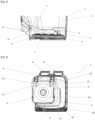
- the bottom wall 8 comprises at least one recess 22 provided on an external face 24 of the bottom wall 8.
- One or more side walls 6 could carry one or more recesses like those carried by the bottom wall 8 on the figures 1 to 4 , and described below.
- the recess(es) are formed on an internal face 28 of the side wall(s) 6, which forms one or more bosses on an external face of the side wall(s) 6.
- figures 1 to 4 illustrate a case in which the bottom wall 8 carries two recesses 22 made at two angles of the bottom wall 8 (allowing different positionings of the wheel axle to be considered), each recess being adjacent to at least a side wall 6, with two side walls 6 in the case illustrated.
- Each recess 22 is formed by two faces, connected by an edge 25, extending into the waste storage volume. As explained above, this shape is simple to produce (simple tools), leads to a limited loss of volume, and makes it possible to stiffen a wall.
- the number and shape of the recess(es) 22 may vary. It could be a single recess 22 in one corner of the bottom wall 8, four recesses 22 at the four corners of the bottom wall 8, a single recess 22 extending beyond a single angle of the bottom wall 8 on the periphery of the latter or crossing it, etc.
- a provision of one or more recesses 22 at one or more angles of the bottom wall 8 makes it possible to limit the loss of internal waste storage volume in the tank 4.
- the Figure 4 illustrates bosses formed on an internal face 26 of the bottom wall 8, bosses formed by the recesses 22. These bosses are located so as to have only a limited impact on the waste storage volume of the tank 4.
- the recesses 22 are arranged on the bottom wall 8 so as to accommodate the wheel axle 7 placed in the second waste collection bin 2' when the waste collection bin 2 is stacked on said second waste collection bin 2'.
- the choice of the positioning and the shape of the recess(es), here the recesses 22, are dictated by the objective of accommodating the wheel axle 7 present in the bottom of a tank 4 of the second 2' waste collection bin.
- the positioning of recesses 22 in the corners of the bottom wall 8 is adapted to accommodate a raised end of the wheel axle 7 also arranged diagonally in the bottom of the second waste collection bin 2'.
- Other shapes could be advantageous in the event of different positioning of the wheel axle 7 in the bottom of the tank of the second waste collection bin 2'.
- the recess(es), for example the recesses 22, are dimensioned so as to be pressed against the wheel axle 7.
- a surface of the recesses 22 accommodating the wheel axle 7 extends in a direction parallel to an axis longitudinal of the wheel axle when it is pressed against it.
- a lateral face of the wheel axle 7, that is to say the face winding around the circular bases in the case of a tubular wheel axle, is pressed against the external face 24 of the bottom wall 8.
- This is visible on the figure 1 illustrating the wheel axle 7 placed in the second waste collection bin 2', one end of which 7' is placed against a recess 22 of the external face 24 of the bottom wall 8.
Landscapes
- Engineering & Computer Science (AREA)
- Mechanical Engineering (AREA)
- Refuse Receptacles (AREA)
Applications Claiming Priority (2)
| Application Number | Priority Date | Filing Date | Title |
|---|---|---|---|
| FR2210266A FR3140619A1 (fr) | 2022-10-06 | 2022-10-06 | Bac de collecte de déchets |
| FR2300193A FR3140618B1 (fr) | 2022-10-06 | 2023-01-09 | Bac de collecte de déchets |
Publications (1)
| Publication Number | Publication Date |
|---|---|
| EP4349737A1 true EP4349737A1 (de) | 2024-04-10 |
Family
ID=88206946
Family Applications (1)
| Application Number | Title | Priority Date | Filing Date |
|---|---|---|---|
| EP23202047.9A Pending EP4349737A1 (de) | 2022-10-06 | 2023-10-06 | Abfallsammelbehälter |
Country Status (1)
| Country | Link |
|---|---|
| EP (1) | EP4349737A1 (de) |
Citations (2)
| Publication number | Priority date | Publication date | Assignee | Title |
|---|---|---|---|---|
| US5465844A (en) * | 1994-04-28 | 1995-11-14 | Compagne Plastic Omnium | Wheeled nestable refuse container |
| US20060232029A1 (en) * | 2005-04-14 | 2006-10-19 | Cascade Engineering, Inc. | Stackable refuse cart |
-
2023
- 2023-10-06 EP EP23202047.9A patent/EP4349737A1/de active Pending
Patent Citations (2)
| Publication number | Priority date | Publication date | Assignee | Title |
|---|---|---|---|---|
| US5465844A (en) * | 1994-04-28 | 1995-11-14 | Compagne Plastic Omnium | Wheeled nestable refuse container |
| US20060232029A1 (en) * | 2005-04-14 | 2006-10-19 | Cascade Engineering, Inc. | Stackable refuse cart |
Similar Documents
| Publication | Publication Date | Title |
|---|---|---|
| WO1999054224A2 (fr) | Bac de conditionnement en matiere plastique alveolaire et ensemble comprenant un tel bac et son couvercle | |
| FR2659633A1 (fr) | Poubelle a chariot amovible. | |
| EP4349737A1 (de) | Abfallsammelbehälter | |
| FR3140618A1 (fr) | Bac de collecte de déchets | |
| EP3034376B1 (de) | Transportanordnung für zerlegbare schubkarren | |
| EP3772433B1 (de) | Wellenbrecher eines tanks für den transport von flüssigen produkten, und entsprechender tank | |
| EP1711406A1 (de) | Faltbarer, rechtwinkliger parallelepipedischer kasten | |
| EP2628688A1 (de) | Verstauungskasten | |
| EP0179962A1 (de) | Verbindungsprofil | |
| EP1098819A1 (de) | Transportvorrichtung für blutbeutel | |
| FR2826330A1 (fr) | Chariot notamment pour le transport de piles de conteneurs | |
| BE703932A (de) | ||
| FR2832128A1 (fr) | Bidon a regions d'aretes ascendantes convexes | |
| EP0474544A1 (de) | Verstärkung für Metallbehälter | |
| FR2559127A1 (fr) | Perfectionnements apportes aux structures de pietements pour conteneurs ou similaires et conteneurs equipes de tels systemes | |
| EP0814005A1 (de) | Kasten mit Keil | |
| EP3845473B1 (de) | Abfallsammelbehälter mit seitlichen abstufungen | |
| EP2409935A1 (de) | Flexibler Behälter | |
| EP1603791A2 (de) | Ersatzradbehälter und rückwärtige konstruktionsausführung eines mit dem behälter versehenen fahrzeugs | |
| EP1044867B1 (de) | Wagenkasten eines Industriefahrzeuges, Verfahren zu seiner Herstellung und Industriefahrzeug mit so einem Wagenkasten | |
| EP1312552A1 (de) | Polyedrischer Kanister mit seitlicher Verstärkung | |
| EP2500236B1 (de) | Verstärkte Schubkarre, die mit einem Mittelteil zur Stütze, Halterung und Verstärkung ausgestattet ist | |
| EP4397601A1 (de) | Trennwand für abfallsammelbehälter | |
| FR3156764A1 (fr) | Dispositif de fermeture d’un fût par une personne unique | |
| EP1977642A1 (de) | Vorrichtung zur Anbringung eines zumindest teilweise flachen Gegenstands an der Wand eines Behälters |
Legal Events
| Date | Code | Title | Description |
|---|---|---|---|
| PUAI | Public reference made under article 153(3) epc to a published international application that has entered the european phase |
Free format text: ORIGINAL CODE: 0009012 |
|
| STAA | Information on the status of an ep patent application or granted ep patent |
Free format text: STATUS: THE APPLICATION HAS BEEN PUBLISHED |
|
| AK | Designated contracting states |
Kind code of ref document: A1 Designated state(s): AL AT BE BG CH CY CZ DE DK EE ES FI FR GB GR HR HU IE IS IT LI LT LU LV MC ME MK MT NL NO PL PT RO RS SE SI SK SM TR |
|
| RAP3 | Party data changed (applicant data changed or rights of an application transferred) |
Owner name: SULO FRANCE |
|
| STAA | Information on the status of an ep patent application or granted ep patent |
Free format text: STATUS: REQUEST FOR EXAMINATION WAS MADE |
|
| 17P | Request for examination filed |
Effective date: 20240930 |
|
| RBV | Designated contracting states (corrected) |
Designated state(s): AL AT BE BG CH CY CZ DE DK EE ES FI FR GB GR HR HU IE IS IT LI LT LU LV MC ME MK MT NL NO PL PT RO RS SE SI SK SM TR |
|
| GRAP | Despatch of communication of intention to grant a patent |
Free format text: ORIGINAL CODE: EPIDOSNIGR1 |
|
| STAA | Information on the status of an ep patent application or granted ep patent |
Free format text: STATUS: GRANT OF PATENT IS INTENDED |
|
| INTG | Intention to grant announced |
Effective date: 20250130 |
|
| GRAJ | Information related to disapproval of communication of intention to grant by the applicant or resumption of examination proceedings by the epo deleted |
Free format text: ORIGINAL CODE: EPIDOSDIGR1 |
|
| STAA | Information on the status of an ep patent application or granted ep patent |
Free format text: STATUS: REQUEST FOR EXAMINATION WAS MADE |
|
| STAA | Information on the status of an ep patent application or granted ep patent |
Free format text: STATUS: EXAMINATION IS IN PROGRESS |
|
| INTC | Intention to grant announced (deleted) | ||
| 17Q | First examination report despatched |
Effective date: 20250604 |