EP4350109A2 - Transportable shut-off system for closing lift shaft openings during construction and for temporary magazine areas in new buildings - Google Patents
Transportable shut-off system for closing lift shaft openings during construction and for temporary magazine areas in new buildings Download PDFInfo
- Publication number
- EP4350109A2 EP4350109A2 EP24159809.3A EP24159809A EP4350109A2 EP 4350109 A2 EP4350109 A2 EP 4350109A2 EP 24159809 A EP24159809 A EP 24159809A EP 4350109 A2 EP4350109 A2 EP 4350109A2
- Authority
- EP
- European Patent Office
- Prior art keywords
- shut
- profiles
- barrier
- elements
- fastening
- Prior art date
- Legal status (The legal status is an assumption and is not a legal conclusion. Google has not performed a legal analysis and makes no representation as to the accuracy of the status listed.)
- Pending
Links
Images

Classifications
-
- E—FIXED CONSTRUCTIONS
- E04—BUILDING
- E04G—SCAFFOLDING; FORMS; SHUTTERING; BUILDING IMPLEMENTS OR AIDS, OR THEIR USE; HANDLING BUILDING MATERIALS ON THE SITE; REPAIRING, BREAKING-UP OR OTHER WORK ON EXISTING BUILDINGS
- E04G21/00—Preparing, conveying, or working-up building materials or building elements in situ; Other devices or measures for constructional work
- E04G21/32—Safety or protective measures for persons during the construction of buildings
- E04G21/3204—Safety or protective measures for persons during the construction of buildings against falling down
- E04G21/3223—Means supported by building floors or flat roofs, e.g. safety railings
- E04G21/3233—Means supported by building floors or flat roofs, e.g. safety railings without permanent provision in the floor or roof
-
- E—FIXED CONSTRUCTIONS
- E04—BUILDING
- E04G—SCAFFOLDING; FORMS; SHUTTERING; BUILDING IMPLEMENTS OR AIDS, OR THEIR USE; HANDLING BUILDING MATERIALS ON THE SITE; REPAIRING, BREAKING-UP OR OTHER WORK ON EXISTING BUILDINGS
- E04G25/00—Shores or struts; Chocks
- E04G25/04—Shores or struts; Chocks telescopic
-
- E—FIXED CONSTRUCTIONS
- E04—BUILDING
- E04G—SCAFFOLDING; FORMS; SHUTTERING; BUILDING IMPLEMENTS OR AIDS, OR THEIR USE; HANDLING BUILDING MATERIALS ON THE SITE; REPAIRING, BREAKING-UP OR OTHER WORK ON EXISTING BUILDINGS
- E04G5/00—Component parts or accessories for scaffolds
- E04G5/14—Railings
- E04G2005/148—Railings latticed or netted
-
- E—FIXED CONSTRUCTIONS
- E04—BUILDING
- E04G—SCAFFOLDING; FORMS; SHUTTERING; BUILDING IMPLEMENTS OR AIDS, OR THEIR USE; HANDLING BUILDING MATERIALS ON THE SITE; REPAIRING, BREAKING-UP OR OTHER WORK ON EXISTING BUILDINGS
- E04G25/00—Shores or struts; Chocks
- E04G2025/006—Heads therefor, e.g. pivotable
Definitions
- the subject matter of the invention is a portable barrier system for closing floor and ceiling openings during the construction phase and for the creation of temporarily required storage areas in new buildings according to the preamble of patent claims 1 and 4.
- openings for the lift shaft and stairs must be created in the walls on each floor. These openings always pose a danger, as with each additional floor, falling into the lift shaft or through several floors in the stairwell area becomes more dangerous.
- Today, such openings are usually closed with beams attached to the walls at the side of the light shaft opening and formwork panels attached in front of them.
- the construction of such temporary structures is complex, as expensive construction timber has to be sawn to size and, on the other hand, dismantled later, which is labor-intensive.
- Another A major disadvantage is that such temporary formwork cannot be opened for a short time or temporarily to provide access to the lift shaft.
- the openings or apertures in the floors and ceilings also often have to be made accessible during the construction phase in order to be able to transport crane loads or large elements through them, for example.
- a further known arrangement for securing elevator shaft doors is the door which is automatically moved from an open position to a closed position by a vertical shift of its center of gravity. This is achieved by the two door hinges, namely the upper and lower door hinges, not having coaxial pivot axes. Furthermore, the upper and lower beams of the elevator shaft door can be extended by telescopic extensions which engage in them, thus changing the width of the sliding door.
- Such an arrangement is designed as a single-purpose door and changing the width of the door or the door panel is complex and the manufacture of the door hinges is expensive.
- the CH700375 Furthermore, the known arrangement can only be set up with the fastening device attached to it. Furthermore, this arrangement cannot be used for the creation of temporary magazines on construction sites.
- An object of the present invention is to provide a barrier system for elevator shafts as well as floor and ceiling openings and for the creation of temporary magazines in new buildings, which can be set up and dismantled on the construction site with little effort.
- a further object of the invention is to create a barrier system which can remain on site during the entire construction phase and does not hinder the continuation of work such as plastering, painting, carpentry, etc. during the construction phase.
- a further object of the invention is to create a barrier system which is height-adjustable during use in order to be able to compensate for applied coverings such as subfloors without dismantling.
- a further object of the invention is to provide a barrier system which can be attached to commercially available ceiling supports.
- the barrier system according to the invention has the advantage that it can be set up and dismantled again during the construction period without damaging walls and ceilings and that it can be set up in such a way that all subsequent work after the Construction of the partial structures (shell) can remain in place.
- a particular advantage is that the barrier system can be used not only to close lift shaft openings, but also all types of openings in floors and ceilings. It can be constructed by one person, as the fastening element, e.g. a support, and the individual barrier elements can be brought to the construction site individually and assembled individually. In a special design, the barrier elements can be connected directly to one another without the aid of fastening elements. In this way, floor openings in particular can be provided with a fence.
- the barrier system advantageously makes it possible to attach and remove the barrier element or elements without tools and using commercially available ceiling supports as fastening elements at any point without damaging the building.
- the barrier element or its position can also be adjusted vertically and adapted to the height of the floor that changes during the construction phase. This is achieved by simply moving the hinge parts on the fastening element.
- Support plates with claws which are arranged at the ends of the fastening element, can ensure a secure hold on the floor and ceiling.
- the barrier element or elements comprise a frame made of vertically and horizontally arranged profiles that are welded together or otherwise connected. Bars, grids or plates are inserted between the profiles. These increase the strength of the barrier element and thus the safety of the barrier.
- Two-part hinge arrangements are designed as connecting elements between the fastening element and the barrier element, which enable easy hooking and unhooking and which, if desired, cause the barrier element to close automatically by means of mutual contact surfaces that run in a helical manner or are arranged at a 45° angle.
- a second shut-off element is arranged on the first shut-off element, which can be moved and locked laterally relative to the first shut-off element.
- the two shut-off elements are connected to one another by simple sliding blocks attached to pins.
- the guides for the sliding blocks can consist of C-shaped profiles in which the sliding blocks are guided. Rollers or roller bearings can also be used instead of sliding blocks.
- the two shut-off elements, which can be moved relative to one another, can be locked and fixed at any desired width.
- At least two bolt-slot nut connections are arranged in the area of the respective edges that overlap.
- two horizontally running tubular frame parts are arranged in pairs in the area of the upper edge and the lower edge on the first barrier element.
- Two individual profiles are arranged on the second barrier element in such a way that, when the two barrier elements are arranged one above the other, they reach the space between the profiles on the first barrier element.
- Bolts lead from the second barrier element through the profiles arranged in pairs on the first barrier element and end in end plates that rest on the outside of the profiles arranged in pairs.
- barrier elements Another use of the barrier elements is to attach them to fastening elements such as ceiling supports that mark out a space. In this way, it is possible to open up the marked out space between the fastening elements clamped between the floor and ceiling and to enter.
- the assembly and dismantling of a storage area created in this way in a building is carried out without tools and all elements can be used as often as required.
- the laborious construction of a storage area from wooden beams and panels can thus be dispensed with.
- the hinge parts which have slanted contact surfaces, allow the barrier elements to always return to the closed position without external influence, unless they are held by a human hand or otherwise prevented from swinging back. This ensures that openings are not left open unattended and people cannot fall.
- the barrier elements can also be locked to the fastening elements with little effort, e.g. with padlocks, so that access to openings is denied even when the construction site is unattended.
- shut-off elements are designated with reference numeral 1 and two fastening elements with reference numeral 3.
- Each shut-off element 1 comprises a rectangular frame made of two first, vertically arranged Profiles 5 and two second horizontally arranged profiles 7.
- the first and second profiles 5, 7 are connected to one another at their ends. Additional corner reinforcements such as a base plate 11 or corner angle plates can increase the stability of the barrier element 1.
- the two vertical profiles 5 of the barrier elements 1 can also be connected and reinforced by further, i.e. third profiles 13.
- Fillings 15 are attached between the profiles 5, 7 and 13, which prevent people from passing through and tools from falling down. Bars 17, aligned vertically or horizontally, or a grid or net 19 can be used as fillings 15.
- Fasteners 21 can be arranged on the first profile 5 on the left-hand side or on both sides.
- hinge elements 23 which can be attached to the fastening element 3 in a detachable and movable manner.
- the hinge elements 23 are directly connected to the fastening element 3.
- the hinge elements 23 are connected to the fastening element 3 in a vertically movable and lockable manner.
- the hinge elements 23 are arranged on clamps 25, which clamps 25 wrap around the tubular lower part 27 of the fastening element 3, e.g. a ceiling support. By loosening or tightening clamping elements such as screws 29, the clamps 25 and the hinge elements 23 attached thereto are moved vertically.
- the two clamps 25 can be connected to one another by a rod 31 running parallel to the lower tube 27 in order to enable synchronous displacement (rod shown in broken lines).
- one of the two clamping screws 29 can be dispensed with.
- the two hinge elements 23 can be attached to a casing tube which is arranged so as to be axially displaceable on the lower tube 27 of the fastening element 3.
- the casing tube (not shown) can be held at the desired height either by means of stopper elements such as bolts which penetrate the lower tube.
- stopper elements such as bolts which penetrate the lower tube.
- nuts can also be arranged on a thread arranged on the lower tube, with which the height of the casing tube and thus the hinges arranged therein can be continuously adjusted.
- the fastening element 3 comprises, in addition to the lower tube 27, a second upper tube 33, which can engage telescopically in the lower tube 27.
- the upper tube 33 can by means of an adjustment device 35 (not described in more detail) and thus the height of the fastening element can be determined.
- the fastening element 3 can be clamped between the floor and the ceiling of a room using the adjustment device 35.
- Support plates 37 can be attached to the ends of the lower tube 27 and the upper tube 33, on which pointed prongs 39 are formed.
- Bases 39 can be arranged on the support plates 37, which remain on the floor as lost elements in the coverings after the pouring of coverings, for example. This means that the height of the barrier elements 3 does not have to be adjusted when a covering or a slab covering is laid on the floor.
- Handles 51 are preferably arranged on the fastening elements 3, against which the extended locking element 1 comes into contact when the lift opening is closed and, if necessary, can be fastened or locked there with a U-lock on the second fastening element.
- Support surfaces 53 between the upper and lower hinge parts which are arranged at an angle of approximately 45° or are helically formed, ensure that the shut-off element 1 always rotates from the open position to the closed position and thus safely covers the opening cross-section of lift shaft openings.
- two essentially identical barrier elements 1 are connected to one another in a transversely movable manner by guide profiles 39 and sliding blocks 41 or rollers guided therein.
- the guide profiles 39 can be attached to the second, horizontally positioned profiles 7 or additionally to the profile 13 of the barrier element 1, or they themselves form the second profiles 7, which connect the two vertical first profiles 5 to one another.
- additional hinges can be arranged on the vertical profiles 5 of the barrier elements, with two upwardly directed hinge pins being attached to one side of the barrier element and Sleeves are attached to the profile on the opposite side at the appropriate height, the inner diameter of which corresponds to the diameter of the pins on the opposite side.
- the horizontal second profile 7 has a C-shaped cross-section, the laterally extending slot 7' of which is directed towards the second shut-off element.
- the second profile 7 consists of a rectangular profile. The latter is penetrated by a bolt 43, to the right-hand end of which a sliding block 41 is fastened.
- a nut 57 On the left-hand end there is a nut 57, preferably a self-locking nut.
- sliding blocks 41 with bolts 43 are arranged on the second profile 7 at the upper edge of the shut-off element and the same number on the lower second profile 7.
- the sliding block 41 can be arranged as in Figure 6 shown as a flat disc or flat rectangular plate.
- a A slotted nut 41 with a T-shaped cross-section can be provided, which engages wedge-like in the slot 7' on the profile 7 and partially fills the rest of the cross-section of the second profile 7 essentially completely.
- the slotted nut 41 slides along the edges on the slot 7', and not the bolt 43 as in Figure 6 shown.
- a ball bearing or a rotatably mounted disk can be mounted on the end of the bolt 43, which is guided in the C-shaped guide profile 39.
- two bolts 43 with sliding blocks 41 are arranged on the overlapping areas of the guide profiles 39 (when the shut-off elements 1 are pulled out) in order to prevent tilting when the shut-off elements 1 are pulled out or pushed together.
- locking screws 45 can be provided at the top and/or bottom or on a middle profile 13 to lock the two interacting shut-off elements 1.
- the bolt 43, which carries the sliding block 41 can also be axially displaceable and thus cause a locking between the two shut-off elements 1.
- the Figures 7 to 10 show a further embodiment of a guide arrangement 55.
- the upper second Profile 7 is made of two profiles with a mutual distance.
- the screw bolt 61 extends between the two profiles 7.
- the three screws 59 for example, can mesh with the corresponding threaded holes in the sliding bearing element 63 or be held there by means of screws.
- the sliding bearing element 63 therefore bears the load of the movable shut-off element and transfers it to the lower of the two profiles 7 arranged parallel and at a distance.
- the sliding bearing element 63 consists of a plastic material that slides well.
- the barrier element 1 can therefore be arranged as a pivoting door in front of a lift shaft opening.
- the fastening element 3 is first aligned exactly vertically on the side or inside the opening between the floor and ceiling of the building and clamped in place.
- a second fastening element 3 is clamped in the same way between the floor and ceiling on the right-hand side of the barrier element 3, and the door can now be hung.
- Locking part 47 serves, on the one hand, to lock a stop part 49 arranged on the right side of the shut-off element 1 positioned in the closed position.
- a lock can be attached to the locking part 47 and the stop part 49, which creates a lockable connection between the two parts.
- the locking part 47 is arranged on the fastening element 3 so that it can be moved vertically, e.g. on the rod 31 - if present - or on a clamp, in order to be able to lock the shut-off element 1 in any vertical position.
- the displaceability of the hinge part 23 on the fastening element 3 serves to lift the barrier element 1, for example, when a covering such as a coating or a slab covering is applied to the raw surface of the building floor.
- a toothed rail 65 similar to that used in rack railways, can be attached to the fastening element 3.
- This rail 65 makes it possible to insert the clamp 25 or the shaft of the screw 29 on the clamp 25 between two teeth of the toothed rod and thus to determine the height not by friction but by positive locking of the connection of the hinges to the fastening element 3.
- the barrier element 1 In another use of the barrier element 1, it can be used as a temporarily erected end wall to form a magazine.
- several barrier elements 1 and the associated fastening elements 3 are arranged between the floor and ceiling of the building, for example of a basement, and the gaps are closed by the barrier elements. In this way, the cordoned off area is accessible from all sides by opening or closing the corresponding barrier element 1.
Landscapes
- Engineering & Computer Science (AREA)
- Architecture (AREA)
- Mechanical Engineering (AREA)
- Civil Engineering (AREA)
- Structural Engineering (AREA)
- Conveying And Assembling Of Building Elements In Situ (AREA)
- Operating, Guiding And Securing Of Roll- Type Closing Members (AREA)
- Pressure Vessels And Lids Thereof (AREA)
- Specific Sealing Or Ventilating Devices For Doors And Windows (AREA)
Abstract
Das transportable Absperrsystem umfasst ein Befestigungselement (3), an welchem ein ein- oder zweiteiliges Absperrelement (1) angelenkt ist. Das Absperrelement ist vorzugsweise zweiteilig, wobei die beiden Teile durch horizontal verlaufende Führungen miteinander verbunden und in jeder Position fixierbar sind.

Description
Gegenstand der Erfindung ist ein transportables Absperrsystem zum Verschliessen von Boden- und Deckenöffnungen während der Bauphase und für die Erstellung von temporär benötigten Magazinbereichen in Neubauten gemäss Oberbegriff der Patentansprüche 1 und 4.The subject matter of the invention is a portable barrier system for closing floor and ceiling openings during the construction phase and for the creation of temporarily required storage areas in new buildings according to the preamble of
Beim Bau von Häusern mit Lift müssen in den Wänden in jedem Stockwerk entsprechende Öffnungen zum Liftschacht und Öffnungen für Treppen erstellt werden. Diese Öffnungen stellen stets eine Gefahr dar, da mit jedem zusätzlichen Stockwerk ein Absturz in den Liftschacht oder durch mehrere Stockwerke im Treppenbereich gefährlicher wird. Üblicherweise werden heute solche Öffnungen mit an den Wänden seitlich der Lichtschachtöffnung befestigten Balken und davor befestigten Schalplatten verschlossen. Einerseits ist der Aufbau solcher Provisorien aufwendig, da teures Bauholz zugesägt und andererseits später arbeitsintensiv wieder abgebaut werden muss. Ein weiterer grosser Nachteil besteht darin, dass bei einer solchen temporären Verschalung diese nicht kurzzeitig oder zeitweilig für den Zugang zum Liftschacht geöffnet werden kann. Auch die Durchbrüche oder Öffnungen in den Böden und Decken müssen während der Bauphase oft zugänglich gemacht werden, um beispielsweise durch diese hindurch Kranlasten oder grosse Elemente befördern zu können.When building houses with a lift, openings for the lift shaft and stairs must be created in the walls on each floor. These openings always pose a danger, as with each additional floor, falling into the lift shaft or through several floors in the stairwell area becomes more dangerous. Today, such openings are usually closed with beams attached to the walls at the side of the light shaft opening and formwork panels attached in front of them. On the one hand, the construction of such temporary structures is complex, as expensive construction timber has to be sawn to size and, on the other hand, dismantled later, which is labor-intensive. Another A major disadvantage is that such temporary formwork cannot be opened for a short time or temporarily to provide access to the lift shaft. The openings or apertures in the floors and ceilings also often have to be made accessible during the construction phase in order to be able to transport crane loads or large elements through them, for example.
Aus der
Eine solche Anordnung ist als Einzwecktür ausgebildet und deren Veränderung der Breite der Tür bzw. der Türfüllung ist aufwendig und die Herstellung der Türbänder kostspielig.Such an arrangement is designed as a single-purpose door and changing the width of the door or the door panel is complex and the manufacture of the door hinges is expensive.
Die aus der
Eine Aufgabe der vorliegenden Erfindung ist die Schaffung eines Absperrsystems für Liftschacht- sowie Boden- und Deckenöffnungen und zur Erstellung von temporären Magazinen in Neubauten, das mit geringem Arbeitsaufwand auf der Baustelle aufgebaut und rückbaubar ist.An object of the present invention is to provide a barrier system for elevator shafts as well as floor and ceiling openings and for the creation of temporary magazines in new buildings, which can be set up and dismantled on the construction site with little effort.
Eine weitere Aufgabe der Erfindung ist die Schaffung eines Absperrsystems, welches während der gesamten Bauphase vor Ort stehen bleiben kann und während der Bauphase die Weiterführung von Arbeiten wie Gipserarbeiten, Malerarbeiten, Schreinerarbeiten etc. nicht behindert. Eine weitere Aufgabe der Erfindung ist die Schaffung eines Absperrsystems, das während dessen Benutzung in der Höhe verstellbar ist, um ohne Demontage aufgebrachte Überzüge wie Unterlagsböden ausgleichen zu können.A further object of the invention is to create a barrier system which can remain on site during the entire construction phase and does not hinder the continuation of work such as plastering, painting, carpentry, etc. during the construction phase. A further object of the invention is to create a barrier system which is height-adjustable during use in order to be able to compensate for applied coverings such as subfloors without dismantling.
Eine weitere Aufgabe der Erfindung ist die Schaffung eines Absperrsystems, welches an handelsüblichen Deckenstützen befestigbar ist.A further object of the invention is to provide a barrier system which can be attached to commercially available ceiling supports.
Gelöst wird diese Aufgabe durch ein Absperrsystem gemäss den Merkmalen der Patentansprüche 1 und 4. Vorteilhafte Ausgestaltungen des Absperrsystems sind in den abhängigen Ansprüchen umschrieben.This object is achieved by a shut-off system according to the features of
Das erfindungsgemässe Absperrsystem hat den Vorteil, dass es ohne Beschädigung von Wänden und Decken während der Bauzeit aufbau- und wieder abbaubar ist und dass es derart aufgestellt werden kann, dass alle Folgearbeiten nach dem Erstellen der Teilbauten (Rohbau) an Ort und Stelle verbleiben kann. Ein besonderer Vorteil besteht darin, dass das Absperrsystem nicht nur zum Verschliessen von Liftschachtöffnungen, sondern alle Arten von Öffnungen auch in Böden und Decken Verwendung finden kann. Es kann durch eine Person erstellt werden, da das Befestigungselement, z.B. eine Stütze, und die einzelnen Absperrelemente einzeln zu Baustelle gebracht werden können und einzeln zusammengefügt werden können. In einer besonderen Ausgestaltung können die Absperrelemente ohne Zuhilfenahme von Befestigungselementen direkt miteinander verbunden werden. Auf diese Weise lassen sich insbesondere Bodenöffnungen mit einem Zaun versehen.The barrier system according to the invention has the advantage that it can be set up and dismantled again during the construction period without damaging walls and ceilings and that it can be set up in such a way that all subsequent work after the Construction of the partial structures (shell) can remain in place. A particular advantage is that the barrier system can be used not only to close lift shaft openings, but also all types of openings in floors and ceilings. It can be constructed by one person, as the fastening element, e.g. a support, and the individual barrier elements can be brought to the construction site individually and assembled individually. In a special design, the barrier elements can be connected directly to one another without the aid of fastening elements. In this way, floor openings in particular can be provided with a fence.
Das Absperrsystem ermöglicht es in vorteilhafter Weise, das Absperrelement oder die Absperrelemente werkzeugfrei und unter Verwendung von handelsüblichen Deckenstützen als Befestigungselemente an beliebiger Stelle ohne Beschädigung der Baute zu befestigen und wieder zu entfernen. Auch kann das Absperrelement bzw. dessen Lage in vertikaler Richtung verstellt werden und an die während der Bauphase veränderte Höhe des Bodens angepasst werden. Dies gelingt durch einfaches Verschieben der Scharnierteile auf dem Befestigungselement.The barrier system advantageously makes it possible to attach and remove the barrier element or elements without tools and using commercially available ceiling supports as fastening elements at any point without damaging the building. The barrier element or its position can also be adjusted vertically and adapted to the height of the floor that changes during the construction phase. This is achieved by simply moving the hinge parts on the fastening element.
Durch Abstützplatten mit Krallen, welche an den Enden des Befestigungselementes angeordnet sind, kann ein sicherer Halt an Boden und Decke gewährleistet werden.Support plates with claws, which are arranged at the ends of the fastening element, can ensure a secure hold on the floor and ceiling.
Das Absperrelement bzw. die Absperrelemente umfassen einen Rahmen aus vertikal und horizontal angeordneten, miteinander verschweissten oder anderweitig verbundenen Profilen. Zwischen den Profilen sind Stäbe, Gitter oder Platten eingesetzt. Diese erhöhen die Festigkeit des Absperrelements und damit die Sicherheit der Absperrung. Als Verbindungselemente zwischen dem Befestigungselement und dem Absperrelement sind zweiteilige Scharnieranordnungen ausgebildet, welche ein einfaches Ein- und Aushängen ermöglichen und welche, falls erwünscht, durch schraubenlinienförmig verlaufende oder in 45°-Winkel angeordnete gegenseitige Auflageflächen ein automatisches Schliessen des Absperrelements bewirken.The barrier element or elements comprise a frame made of vertically and horizontally arranged profiles that are welded together or otherwise connected. Bars, grids or plates are inserted between the profiles. These increase the strength of the barrier element and thus the safety of the barrier. Two-part hinge arrangements are designed as connecting elements between the fastening element and the barrier element, which enable easy hooking and unhooking and which, if desired, cause the barrier element to close automatically by means of mutual contact surfaces that run in a helical manner or are arranged at a 45° angle.
In vorteilhafter Weise ist am ersten Absperrelement ein zweites Absperrelement angeordnet, welches relativ zum ersten Absperrelement seitlich von diesem verschieb- und arretierbar ist. Damit lassen sich Liftschachtöffnungen unterschiedlicher Breite mit ein und derselben Vorrichtung sicher mit über die gesamte Breite stabilen Gittern oder Stäben verschliessen. Die beiden Absperrelemente sind durch einfache an Zapfen befestigte Nutensteine miteinander verbunden. Die Führungen für die Nutensteine können aus C-förmigen Profilen bestehen, in welchen die Nutensteine geführt sind. Es können auch anstelle von Nutensteinen Rollen oder Wälzlager eingesetzt sein. Die beiden gegeneinander verschiebbaren Absperrelemente können in jeder gewünschten Breite arretiert und fixiert werden.Advantageously, a second shut-off element is arranged on the first shut-off element, which can be moved and locked laterally relative to the first shut-off element. This means that lift shaft openings of different widths can be securely closed with one and the same device using stable grids or bars across the entire width. The two shut-off elements are connected to one another by simple sliding blocks attached to pins. The guides for the sliding blocks can consist of C-shaped profiles in which the sliding blocks are guided. Rollers or roller bearings can also be used instead of sliding blocks. The two shut-off elements, which can be moved relative to one another, can be locked and fixed at any desired width.
Um eine Verkeilung während des Verschiebens zu verhindern, sind mindestens zwei Bolzen-Nutensteinverbindungen im Bereich der jeweiligen Kanten, die sich überlappen, angeordnet.To prevent wedging during movement, at least two bolt-slot nut connections are arranged in the area of the respective edges that overlap.
In einer weiteren Ausgestaltung der Führungsanordnung zwischen den beiden Absperrelementen sind am ersten Absperrelement jeweils zwei horizontal verlaufende rohrförmige Rahmenteile paarweise im Bereich der Oberkante und der Unterkante angeordnet. Am zweiten Absperrelement sind zwei einzelne Profile derart angeordnet, dass sie, wenn die beiden Absperrelemente übereinander liegend angeordnet sind, in den Zwischenraum zwischen die Profile am ersten Absperrelement gelangen. Vom zweiten Absperrelement führen Bolzen durch die paarweise angeordneten Profile beim ersten Absperrelement und enden in Endplatten, die an der Aussenseite der paarweise vorliegenden Profile anliegen. Diese Ausführungsform ist äusserst einfach und vor allem im Hinblick auf den Einsatzbereich auf dem Bau absolut schmutzunempfindlich, weil dieser beim Verschieben jeweils durch die Bolzen zur Seite geschoben wird und folglich kein Verklemmen eintreten kann.In a further embodiment of the guide arrangement between the two barrier elements, two horizontally running tubular frame parts are arranged in pairs in the area of the upper edge and the lower edge on the first barrier element. Two individual profiles are arranged on the second barrier element in such a way that, when the two barrier elements are arranged one above the other, they reach the space between the profiles on the first barrier element. Bolts lead from the second barrier element through the profiles arranged in pairs on the first barrier element and end in end plates that rest on the outside of the profiles arranged in pairs. This design is extremely simple and, above all with regard to its use on construction sites, is completely insensitive to dirt because the bolts push the profiles to the side when they are moved, meaning that jamming cannot occur.
In einer weiteren Verwendung der Absperrelemente werden diese an Befestigungselementen wie Deckenstützen, die einen Raum abstecken, angeordnet. Auf diese Weise ist es möglich, den abgesteckten Raum zwischen den zwischen Boden und Decke eingespannten Befestigungselementen zu öffnen und zu betreten. Der Auf- und der Abbau eines derart erzeugten Magazinbereichs in einer Baute erfolgt werkzeugfrei und alle Elemente können beliebig oft verwendet werden. Auf den mühsamen Aufbau eines Magazinbereichs aus Holzbalken und -platten kann damit verzichtet werden.Another use of the barrier elements is to attach them to fastening elements such as ceiling supports that mark out a space. In this way, it is possible to open up the marked out space between the fastening elements clamped between the floor and ceiling and to enter. The assembly and dismantling of a storage area created in this way in a building is carried out without tools and all elements can be used as often as required. The laborious construction of a storage area from wooden beams and panels can thus be dispensed with.
Die mit schrägen Auflageflächen versehenen Scharnierteile ermöglichen es ohne Fremdeinwirkung, dass die Absperrelemente stets in die Verschliessstellung zurückkehren, wenn sie nicht von Menschenhand gehalten oder anderswie am Zurückschwenken gehindert werden. Dadurch wird sichergestellt, dass Öffnungen nicht unbeaufsichtigt offenstehen und Personen abstürzen können. Die Absperrelemente lassen sich auch mit wenig Aufwand, z.B. mit Bügelschlössern, an den Befestigungselementen verschliessen, sodass auch bei unbeaufsichtigter Baustelle der Zutritt zu Öffnungen verwehrt ist.The hinge parts, which have slanted contact surfaces, allow the barrier elements to always return to the closed position without external influence, unless they are held by a human hand or otherwise prevented from swinging back. This ensures that openings are not left open unattended and people cannot fall. The barrier elements can also be locked to the fastening elements with little effort, e.g. with padlocks, so that access to openings is denied even when the construction site is unattended.
Anhand eines illustrierten Ausführungsbeispiels wird das Absperrsystem näher erläutert. Es zeigen:
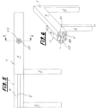
Figur 1- eine Ansicht eines Absperrsystems mit zwei Absperrelementen und ein Befestigungselement, welches das Absperrelement trägt,
Figur 2- einen Vertikalschnitt durch das Absperrsystem gemäss
Figur 1 Figur 3- einen vergrösserten Ausschnitt der Verbindung Befestigungselement/Absperrelement,
Figur 4- einen Horizontalschnitt durch die Absperrelemente,
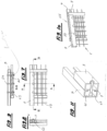
Figur 5- eine Ansicht der linken oberen Ecke der miteinander verbundenen Absperrelemente,
- Figur 6
- einen Querschnitt längs Linie A-A in
Figur 5 Figur 7- eine weitere Ansicht der Absperrelemente mit einer anderen Führungsanordnung,
- Figur 8
- einen Vertikalschnitt längs Linie A-A in
Figur 7 - Figur 9
- ein Horizontalschnitt längs Linie B-B in
Figur 7 - Figur 10
- ein perspektivischer Ausschnitt der oberen Führungsanordnung der beiden Absperrelemente und
- Figur 11
- einen Querschnitt durch die oberen Profile in einer weiteren Ausführungsform.
- Figure 1
- a view of a shut-off system with two shut-off elements and a fastening element which supports the shut-off element,
- Figure 2
- a vertical section through the barrier system according to
Figure 1 , - Figure 3
- an enlarged section of the fastening element/shut-off element connection,
- Figure 4
- a horizontal section through the barrier elements,
- Figure 5
- a view of the upper left corner of the interconnected barrier elements,
- Figure 6
- a cross section along line AA in
Figure 5 shown in perspective, - Figure 7
- another view of the shut-off elements with a different guide arrangement,
- Figure 8
- a vertical section along line AA in
Figure 7 , - Figure 9
- a horizontal section along line BB in
Figure 7 , - Figure 10
- a perspective section of the upper guide arrangement of the two shut-off elements and
- Figure 11
- a cross-section through the upper profiles in another embodiment.
In
Diese umfassen Scharnierelemente 23, welche am Befestigungselement 3 wieder lös- und verschiebbar anbringbar sind. Die Scharnierelemente 23 sind in einer einfachen Ausgestaltung mit dem Befestigungselement 3 direkt verbunden. In einer bevorzugten Ausgestaltung sind die Scharnierelemente 23 vertikal verschieb- und arretierbar mit dem Befestigungselement 3 verbunden.These include
In einer ersten Ausführung sind die Scharnierelemente 23 an Briden 25 angeordnet, welche Briden 25 den rohrförmigen Unterteil 27 des Befestigungselements 3, z.B. einer Deckenstütze umschlingen. Durch Lösen bzw. Anziehen von Klemmelementen wie Schrauben 29 können die Briden 25 und die daran befestigten Scharnierelemente 23 vertikal verschoben werden.In a first embodiment, the
In einer weiter bevorzugten Ausgestaltung können die beiden Briden 25 durch eine parallel zum unteren Rohr 27 verlaufende Stange 31 miteinander verbunden sein, um ein synchrones Verschieben zu ermöglichen (Stange in gebrochenen Linien dargestellt). Bei dieser Ausgestaltung kann auf eine der beiden Spannschrauben 29 verzichtet werden.In a further preferred embodiment, the two
In einer besonders vorteilhaften Ausgestaltung können die beiden Scharnierelemente 23 an einem Hüllrohr befestigt sein, welches auf dem unteren Rohr 27 des Befestigungselements 3 axial verschiebbar angeordnet ist. Das Hüllrohr (keine Abbildung) kann entweder über Stopperelemente, wie Bolzen, die das untere Rohr durchdringen, auf der gewünschten Höhe gehalten werden. Es können aber auch auf einem auf dem unteren Rohr angeordneten Gewinde Muttern angeordnet sein, mit welchen die Höhe des Hüllrohrs und damit den darin angeordneten Scharnieren stufenlos einstellbar ist. Diese Ausführung hat den Vorteil, dass die Höhenverstellung der Absperrelemente 1 jederzeit von einer Person und ohne Demontage der Befestigungselemente 3 erfolgen kann.In a particularly advantageous embodiment, the two
Das Befestigungselement 3 umfasst nebst dem unteren Rohr 27 ein zweites oberes Rohr 33, welches teleskopisch in das untere Rohr 27 eingreifen kann. Das obere Rohr 33 kann durch eine nicht näher umschriebene Verstellvorrichtung 35 verstellt und damit die Höhe des Befestigungselements festgelegt werden. Gleichzeitig kann mit der Verstellvorrichtung 35 das Befestigungselement 3 zwischen dem Boden und der Decke eines Raums eingespannt werden. An den Enden des unteren Rohrs 27 und des oberen Rohrs 33 können Abstützplatten 37 befestigt sein, an denen spitzige Zacken 39 ausgebildet sind.The
An den Abstützplatten 37 können Sockel 39 angeordnet werden, welche z.B. nach dem Giessen von Überzügen als verlorene Elemente in den Überzügen auf dem Boden zurückbleiben. Dadurch muss keine Höhenverstellung der Absperrelemente 3 erfolgen, wenn auf dem Boden ein Überzug oder ein Plattenbelag verlegt wird.
An den Befestigungselementen 3 sind vorzugsweise Griffe 51 angeordnet, an welchen bei verschlossener Liftöffnung das ausgezogene Absperrelement 1 in Anschlag gelangt und falls notwendig dort mit einem Bügelschloss am zweiten Befestigungselement festgemacht oder verschlossen werden kann.
In einem Winkel von ca. 45° liegende oder schraubenförmig ausgebildete Auflageflächen 53 zwischen den oberen und den unteren Scharnierteilen bewirken, dass sich das Absperrelement 1 von der geöffneten Stellung stets in die geschlossene Stellung dreht und so den Öffnungsquerschnitt von Liftschachöffnungen sicher verdeckt.Support surfaces 53 between the upper and lower hinge parts, which are arranged at an angle of approximately 45° or are helically formed, ensure that the shut-off
Um das Absperrsystem an unterschiedlich breite Öffnungen an Liftschächten anpassen zu können, sind zwei im Wesentlichen identische Absperrelemente 1 durch Führungsprofile 39 und darin geführte Nutensteine 41 oder Rollen miteinander transversal verschiebbar verbunden. Die Führungsproifle 39 können an den zweiten, horizontal liegenden Profilen 7 oder zusätzlich auch am Profil 13 des Absperrelements 1 befestigt sein oder sie bilden selbst die zweiten Profile 7, welche die beiden vertikalen ersten Profile 5 miteinander verbinden.In order to be able to adapt the barrier system to openings of different widths in lift shafts, two essentially
In
Für die Erstellung von Zäunen um Bodenöffnungen, die kleiner sind als die maximale Breite des Absperrsystems, können an den vertikal verlaufenden Profilen 5 der Absperrelemente zusätzliche Scharniere angeordnet sein, wobei jeweils auf der einen Seite des Absperrelements zwei nach oben gerichtete Scharnierzapfen befestigt sind und am Profil auf der gegenüberliegenden Seite sind auf der entsprechenden Höhe Hülsen befestigt, deren Innendurchmesser dem Durchmesser der Zapfen auf der gegenüberliegenden Seite entsprechen. Es ist dadurch möglich, die Absperrelemente in beliebigem Winkel nebeneinander aufzustellen, ohne dass dazu Befestigungselemente in Gestalt von Eckenstützen oder dergleichen notwendig sind (keine Abbildungen). Auf diese Weise lassen sich übertrittsichere Zäune beliebiger Form erstellen.For the construction of fences around ground openings that are smaller than the maximum width of the barrier system, additional hinges can be arranged on the
In den
Um eine gleichmässige Belastung der Führungsanordnung zu erhalten, werden beispielsweise drei Nutensteine 41 mit Bolzen 43 am zweiten Profil 7 an der Oberkante des Absperrelements und die gleiche Anzahl am unteren zweiten Profil 7 angeordnet. Der Nutenstein 41 kann wie in
Alternativ zu Nutensteinen 41 können am Ende des Bolzens 43 auch ein Kugellager oder eine drehbar gelagerte Scheibe aufgesetzt sein, die im C-förmigen Führungsprofil 39 geführt ist.As an alternative to sliding
Vorzugsweise sind an den sich überlappenden Bereichen der Führungsprofile 39 (bei ausgezogenen Absperrelementen 1) zwei Bolzen 43 mit Nutensteinen 41 angeordnet, um ein Verkanten während des Ausziehens oder Zusammenschiebens der Absperrelemente 1 zu vermeiden. Zusätzlich können zur Arretierung der beiden zusammenwirkenden Absperrelemente 1 Feststellschrauben 45 oben und/oder unten oder an einem mittleren Profil 13 vorgesehen sein. Alternativ kann auch der Bolzen 43, welcher den Nutenstein 41 trägt, axial verschiebbar sein und so eine Arretierung zwischen den beiden Absperrelementen 1 bewirken.Preferably, two
Die
In einer besonders bevorzugten Ausgestaltung besteht das Schiebelagerelement 63 aus einem gut gleitenden Kunststoffmaterial.In a particularly preferred embodiment, the sliding
Das Absperrelement 1 kann folglich als schwenkbare Tür vor einer Liftschachtöffnung angeordnet sein. Dazu wird vorerst das Befestigungselement 3 seitlich oder innerhalb der Öffnung zwischen Boden und Decke der Baute exakt vertikal ausgerichtet und eingespannt. Ein zweites Befestigungselement 3 wird auf der rechten Seite des Absperrelements 3 in gleicher Art und Weise zwischen Boden und Decke verspannt, nun kann die Tür eingehängt werden.The
Verriegelungsteil 47 dient dazu, einerseits ein entsprechend am Absperrelement 1 auf der rechten Seite angeordnetes Anschlagteil 49 das Absperrelement 1 positioniert in der geschlossenen Position zu halten. Gleichzeitig kann an dem Verriegelungsteil 47 und dem Anschlagteil 49 ein Schloss befestigt sein, welches eine abschliessbare Verbindung der beiden Teile herstellt. In einer bevorzugten Ausbildung ist das Verriegelungsteil 47 am Befestigungselement 3 vertikal verschiebbar angeordnet, z.B. an der Stange 31 - falls vorhanden - oder an einer Bride, um in jeder vertikalen Position des Absperrelements 1 die Verriegelung vornehmen zu können.Locking
Die Verschiebbarkeit der Scharnierteil3 23 am Befestigungselement 3 dient dazu, das Absperrelement 1 beispielsweise anzuheben, wenn auf der rohen Oberfläche des Gebäudebodens ein Belag wie ein Überzug oder ein Plattenbelag aufgebracht wird.The displaceability of the
Befestigungselement 3 verschieben zu können, kann am Befestigungselement 3 eine gezahnte Schiene 65, ähnlich wie sie bei Zahnradbahnen verwendet wird, befestigt sein. Diese Schiene 65 ermöglicht es, die Bride 25 bzw. den Schaft der Schraube 29 an der Bride 25 zwischen zwei Zähnen der gezahnten Stange einzulegen und so die Höhe nicht durch Reibschluss, sondern durch Formschluss der Anbindung der Scharniere am Befestigungselement 3 festzulegen.In order to be able to move the
In einer weiteren Verwendung des Absperrelements 1 kann dieses als temporär aufbaubare Abschlusswand zur Bildung eines Magazins eingesetzt werden. Zu diesem Zweck werden mehrere Absperrelemente 1 und die dazugehörigen Befestigungselemente 3 zwischen Boden und Decke, beispielsweise eines Kellergeschosses, der Baute angeordnet und die Zwischenräume durch die Absperrelemente geschlossen. Auf diese Weise ist der abgesperrte Bereich von allen Seiten zugänglich, indem jeweils das entsprechende Absperrelement 1 geöffnet oder geschlossen werden kann.In another use of the
Claims (15)
dadurch gekennzeichnet, dass
das Absperrelement (1) mit einer rohrförmigen Säule oder einer handelsüblichen Deckenstütze verbindbar ausgebildet ist.Portable barrier system for closing openings during the construction phase and for the creation of temporarily required storage areas in new buildings, comprising a barrier element (1) and a fastening element (3) for fastening the barrier element (1) to a building,
characterized in that
the shut-off element (1) is designed to be connectable to a tubular column or a commercially available ceiling support.
dadurch gekennzeichnet, dass
das Absperrsystem ein erstes und ein zweites Absperrelement (1) umfasst, welche beiden Absperrelemente (1) nebeneinander angeordnet sind, wobei das zweite Absperrelement (1) über das erste Absperrelement (1) stufenlos zur Seite verfahrbar mit dem ersten Absperrelement (1) verbunden ist.Portable barrier system for closing openings on buildings during the construction phase,
characterized in that
the shut-off system comprises a first and a second shut-off element (1), which two shut-off elements (1) are arranged next to one another, wherein the second shut-off element (1) is connected to the first shut-off element (1) via the first shut-off element (1) so as to be continuously movable to the side.
dadurch gekennzeichnet, dass für die Verschiebung des zweiten Absperrelements (1) neben dem ersten Absperrelement (1) mindestens an einem von deren horizontal verlaufenden zweiten Profilen (7) ineinander greifende Führungselemente zur translatorischen Verschiebung des zweiten Absperrelements (1) auf dem ersten Absperrelement (1) ausgebildet sind.Shut-off system according to one of claims 4 to 6,
characterized in that for the displacement of the second shut-off element (1) next to the first shut-off element (1) at least on one of their horizontally extending second profiles (7) interlocking guide elements for translational displacement of the second shut-off element (1) on the first shut-off element (1).
dadurch gekennzeichnet, dass an einem oder mehreren der horizontalen Profile (5,7,13) Mittel zur gegenseitigen Verbindung der Absperrelemente (1) ausgebildet sind.Shut-off system according to one of claims 6 to 8,
characterized in that means for mutually connecting the shut-off elements (1) are formed on one or more of the horizontal profiles (5,7,13).
dadurch gekennzeichnet, dass zwei oder mehrere Führungsprofile (39) verteilt über die Höhe der Absperrmittel (1) angeordnet sind.Shut-off system according to one of claims 7 to 9,
characterized in that two or more guide profiles (39) are arranged distributed over the height of the barrier means (1).
dadurch gekennzeichnet, dass das Befestigungselement (3) an dessen Enden Abstützplatten (37) mit von der Plattenoberfläche wegragende Krallen (39) und/oder in eine Unterlage eingiessbar verlorene Distanzplatten angeordnet sind.Shut-off system according to one of claims 1 to 10,
characterized in that the fastening element (3) is provided with support plates (37) with claws (39) projecting from the plate surface and/or spacer plates which can be cast into a base at its ends.
Applications Claiming Priority (2)
| Application Number | Priority Date | Filing Date | Title |
|---|---|---|---|
| CH00034/20A CH717031A2 (en) | 2020-01-13 | 2020-01-13 | Transportable barrier system for closing openings during the construction phase and for creating temporarily required magazine areas in new buildings. |
| EP21150451.9A EP3848321A3 (en) | 2020-01-13 | 2021-01-07 | Transportable barrier system for closing lift shaft openings during the construction phase and for creating temporarily required magazine areas in new builds |
Related Parent Applications (1)
| Application Number | Title | Priority Date | Filing Date |
|---|---|---|---|
| EP21150451.9A Division EP3848321A3 (en) | 2020-01-13 | 2021-01-07 | Transportable barrier system for closing lift shaft openings during the construction phase and for creating temporarily required magazine areas in new builds |
Publications (2)
| Publication Number | Publication Date |
|---|---|
| EP4350109A2 true EP4350109A2 (en) | 2024-04-10 |
| EP4350109A3 EP4350109A3 (en) | 2024-04-24 |
Family
ID=74105866
Family Applications (2)
| Application Number | Title | Priority Date | Filing Date |
|---|---|---|---|
| EP24159809.3A Pending EP4350109A3 (en) | 2020-01-13 | 2021-01-07 | Transportable shut-off system for closing lift shaft openings during construction and for temporary magazine areas in new buildings |
| EP21150451.9A Withdrawn EP3848321A3 (en) | 2020-01-13 | 2021-01-07 | Transportable barrier system for closing lift shaft openings during the construction phase and for creating temporarily required magazine areas in new builds |
Family Applications After (1)
| Application Number | Title | Priority Date | Filing Date |
|---|---|---|---|
| EP21150451.9A Withdrawn EP3848321A3 (en) | 2020-01-13 | 2021-01-07 | Transportable barrier system for closing lift shaft openings during the construction phase and for creating temporarily required magazine areas in new builds |
Country Status (2)
| Country | Link |
|---|---|
| EP (2) | EP4350109A3 (en) |
| CH (1) | CH717031A2 (en) |
Citations (1)
| Publication number | Priority date | Publication date | Assignee | Title |
|---|---|---|---|---|
| CH700375A2 (en) | 2009-02-11 | 2010-08-13 | Maegert Bautechnik Ag | Lift shaft openings protecting arrangement, has lift shaft door connected with wall holder by combination of hinges and automatically passing from opened position to closed position over balance point of door by vertical displacement |
Family Cites Families (10)
| Publication number | Priority date | Publication date | Assignee | Title |
|---|---|---|---|---|
| US3662993A (en) * | 1971-04-07 | 1972-05-16 | Anthony Lionetto | Protective guard fixture |
| JPH08240010A (en) * | 1995-03-03 | 1996-09-17 | Maki Kogyo Kk | Vertical curing device |
| KR20010001357U (en) * | 1999-06-28 | 2001-01-15 | 최문호 | Safety work bench for elevator setup |
| DE20203949U1 (en) * | 2002-03-12 | 2002-07-18 | Huang, Jian-Fa, Kaohsiung | hinge |
| US6976557B2 (en) * | 2004-02-27 | 2005-12-20 | Aluma Enterprises Inc. | Toeboard system for scaffolding |
| CA2515750C (en) * | 2005-08-10 | 2014-06-03 | Jonathan Jonny Melic | Locking and lifting mechanism for safety fence support post |
| FR2927920B1 (en) * | 2008-02-25 | 2012-07-13 | Nord Coffrage | SLIDING BAY |
| GB2487505B (en) * | 2010-10-21 | 2012-12-12 | Znd Uk Ltd | Gate assembly |
| KR101744585B1 (en) * | 2014-01-06 | 2017-06-08 | 주식회사 듀오텍 | Auto closing type safety gate |
| GB201601315D0 (en) * | 2016-01-25 | 2016-03-09 | Brand Energy & Infrastructure Services Uk Ltd | A safety screen |
-
2020
- 2020-01-13 CH CH00034/20A patent/CH717031A2/en unknown
-
2021
- 2021-01-07 EP EP24159809.3A patent/EP4350109A3/en active Pending
- 2021-01-07 EP EP21150451.9A patent/EP3848321A3/en not_active Withdrawn
Patent Citations (2)
| Publication number | Priority date | Publication date | Assignee | Title |
|---|---|---|---|---|
| CH700375A2 (en) | 2009-02-11 | 2010-08-13 | Maegert Bautechnik Ag | Lift shaft openings protecting arrangement, has lift shaft door connected with wall holder by combination of hinges and automatically passing from opened position to closed position over balance point of door by vertical displacement |
| CH700375B1 (en) | 2009-02-11 | 2013-05-15 | Maegert Bautechnik Ag | Arrangement for securing the lift shaft openings. |
Also Published As
| Publication number | Publication date |
|---|---|
| EP3848321A3 (en) | 2021-09-22 |
| EP3848321A2 (en) | 2021-07-14 |
| EP4350109A3 (en) | 2024-04-24 |
| CH717031A2 (en) | 2021-07-15 |
Similar Documents
| Publication | Publication Date | Title |
|---|---|---|
| DE60304219T2 (en) | DEVICE FOR MANUFACTURING A MOVABLE WALL CONSTRUCTION | |
| EP3358107A1 (en) | Formwork clamp | |
| DE102019107430A1 (en) | Connection strip for ceiling formwork | |
| AT518814A1 (en) | Fence system and assembly process for a fence system | |
| EP2798133B1 (en) | Panel for a system ceiling formwork, and a system ceiling formwork | |
| DE102004004883B4 (en) | Ceiling formwork panel and system ceiling formwork | |
| AT523944B1 (en) | railing module | |
| EP4350109A2 (en) | Transportable shut-off system for closing lift shaft openings during construction and for temporary magazine areas in new buildings | |
| DE102013000105A1 (en) | Device for preventing crashes | |
| AT396162B (en) | DEVICE FOR APPLYING RAILING BOARDS OD. DGL. | |
| DE3331811A1 (en) | Scaffold structure, in particular for building sites | |
| EP3211138A1 (en) | Substructure for a structure | |
| DE102016111211A1 (en) | Formwork system for the construction of low construction sections of in-situ concrete | |
| EP0851074B1 (en) | Scaffolding for platform, staging or floorshuttering | |
| DE19636550C2 (en) | Stage covering for console stages or bridging platforms as well as method for assembling a console stage | |
| DE3048043A1 (en) | Ceiling formwork support structure - has folding legs swinging and set at angle round telescopic upright | |
| DE2263371B2 (en) | DEVICE FOR FASTENING AT LEAST ONE PART OF A PRECAST CONCRETE PART TO A BUILDING WALL | |
| AT400467B (en) | AUXILIARY DEVICE FOR USE IN THE AREA OF WINDOW OR PASSWAY OPENINGS AND CORNERS FOR THE CREATION OF WALLS MADE FROM A WALL | |
| EP3179002B1 (en) | Accommodation provided with flexible base | |
| DE19648988A1 (en) | Dismantlable facade scaffolding | |
| EP0591629A1 (en) | Method and arrangement for mounting insulating or cladding panels | |
| WO2024208620A1 (en) | Foldable railing and assembly thereof | |
| DE102022003723A1 (en) | wall gauge | |
| CH707099A2 (en) | Fastening system for the adjustable mounting of covering elements. | |
| DE1556719C (en) | Pallet-like means of transport |
Legal Events
| Date | Code | Title | Description |
|---|---|---|---|
| PUAI | Public reference made under article 153(3) epc to a published international application that has entered the european phase |
Free format text: ORIGINAL CODE: 0009012 |
|
| STAA | Information on the status of an ep patent application or granted ep patent |
Free format text: STATUS: THE APPLICATION HAS BEEN PUBLISHED |
|
| REG | Reference to a national code |
Ref country code: DE Ref legal event code: R079 Free format text: PREVIOUS MAIN CLASS: E05F0001060000 Ipc: B66B0013300000 |
|
| PUAL | Search report despatched |
Free format text: ORIGINAL CODE: 0009013 |
|
| AC | Divisional application: reference to earlier application |
Ref document number: 3848321 Country of ref document: EP Kind code of ref document: P |
|
| AK | Designated contracting states |
Kind code of ref document: A2 Designated state(s): AL AT BE BG CH CY CZ DE DK EE ES FI FR GB GR HR HU IE IS IT LI LT LU LV MC MK MT NL NO PL PT RO RS SE SI SK SM TR |
|
| AK | Designated contracting states |
Kind code of ref document: A3 Designated state(s): AL AT BE BG CH CY CZ DE DK EE ES FI FR GB GR HR HU IE IS IT LI LT LU LV MC MK MT NL NO PL PT RO RS SE SI SK SM TR |
|
| RIC1 | Information provided on ipc code assigned before grant |
Ipc: E04G 25/00 20060101ALI20240320BHEP Ipc: E04G 5/14 20060101ALI20240320BHEP Ipc: E05F 1/06 20060101ALI20240320BHEP Ipc: E05D 5/10 20060101ALI20240320BHEP Ipc: E04G 25/04 20060101ALI20240320BHEP Ipc: E04G 21/32 20060101ALI20240320BHEP Ipc: B66B 13/30 20060101AFI20240320BHEP |
|
| STAA | Information on the status of an ep patent application or granted ep patent |
Free format text: STATUS: REQUEST FOR EXAMINATION WAS MADE |
|
| 17P | Request for examination filed |
Effective date: 20241023 |
|
| RBV | Designated contracting states (corrected) |
Designated state(s): AL AT BE BG CH CY CZ DE DK EE ES FI FR GB GR HR HU IE IS IT LI LT LU LV MC MK MT NL NO PL PT RO RS SE SI SK SM TR |
|
| STAA | Information on the status of an ep patent application or granted ep patent |
Free format text: STATUS: EXAMINATION IS IN PROGRESS |
|
| 17Q | First examination report despatched |
Effective date: 20241213 |
|
| GRAP | Despatch of communication of intention to grant a patent |
Free format text: ORIGINAL CODE: EPIDOSNIGR1 |
|
| STAA | Information on the status of an ep patent application or granted ep patent |
Free format text: STATUS: GRANT OF PATENT IS INTENDED |
|
| INTG | Intention to grant announced |
Effective date: 20260209 |