EP4350109A2 - Système de fermeture transportable pour obturer des ouvertures de cage d'ascenseur pendant la phase de construction et pour créer des zones de magasin requises temporairement dans des constructions - Google Patents
Système de fermeture transportable pour obturer des ouvertures de cage d'ascenseur pendant la phase de construction et pour créer des zones de magasin requises temporairement dans des constructions Download PDFInfo
- Publication number
- EP4350109A2 EP4350109A2 EP24159809.3A EP24159809A EP4350109A2 EP 4350109 A2 EP4350109 A2 EP 4350109A2 EP 24159809 A EP24159809 A EP 24159809A EP 4350109 A2 EP4350109 A2 EP 4350109A2
- Authority
- EP
- European Patent Office
- Prior art keywords
- shut
- profiles
- barrier
- elements
- fastening
- Prior art date
- Legal status (The legal status is an assumption and is not a legal conclusion. Google has not performed a legal analysis and makes no representation as to the accuracy of the status listed.)
- Pending
Links
Images

Classifications
-
- E—FIXED CONSTRUCTIONS
- E04—BUILDING
- E04G—SCAFFOLDING; FORMS; SHUTTERING; BUILDING IMPLEMENTS OR AIDS, OR THEIR USE; HANDLING BUILDING MATERIALS ON THE SITE; REPAIRING, BREAKING-UP OR OTHER WORK ON EXISTING BUILDINGS
- E04G21/00—Preparing, conveying, or working-up building materials or building elements in situ; Other devices or measures for constructional work
- E04G21/32—Safety or protective measures for persons during the construction of buildings
- E04G21/3204—Safety or protective measures for persons during the construction of buildings against falling down
- E04G21/3223—Means supported by building floors or flat roofs, e.g. safety railings
- E04G21/3233—Means supported by building floors or flat roofs, e.g. safety railings without permanent provision in the floor or roof
-
- E—FIXED CONSTRUCTIONS
- E04—BUILDING
- E04G—SCAFFOLDING; FORMS; SHUTTERING; BUILDING IMPLEMENTS OR AIDS, OR THEIR USE; HANDLING BUILDING MATERIALS ON THE SITE; REPAIRING, BREAKING-UP OR OTHER WORK ON EXISTING BUILDINGS
- E04G25/00—Shores or struts; Chocks
- E04G25/04—Shores or struts; Chocks telescopic
-
- E—FIXED CONSTRUCTIONS
- E04—BUILDING
- E04G—SCAFFOLDING; FORMS; SHUTTERING; BUILDING IMPLEMENTS OR AIDS, OR THEIR USE; HANDLING BUILDING MATERIALS ON THE SITE; REPAIRING, BREAKING-UP OR OTHER WORK ON EXISTING BUILDINGS
- E04G5/00—Component parts or accessories for scaffolds
- E04G5/14—Railings
- E04G2005/148—Railings latticed or netted
-
- E—FIXED CONSTRUCTIONS
- E04—BUILDING
- E04G—SCAFFOLDING; FORMS; SHUTTERING; BUILDING IMPLEMENTS OR AIDS, OR THEIR USE; HANDLING BUILDING MATERIALS ON THE SITE; REPAIRING, BREAKING-UP OR OTHER WORK ON EXISTING BUILDINGS
- E04G25/00—Shores or struts; Chocks
- E04G2025/006—Heads therefor, e.g. pivotable
Definitions
- the subject matter of the invention is a portable barrier system for closing floor and ceiling openings during the construction phase and for the creation of temporarily required storage areas in new buildings according to the preamble of patent claims 1 and 4.
- openings for the lift shaft and stairs must be created in the walls on each floor. These openings always pose a danger, as with each additional floor, falling into the lift shaft or through several floors in the stairwell area becomes more dangerous.
- Today, such openings are usually closed with beams attached to the walls at the side of the light shaft opening and formwork panels attached in front of them.
- the construction of such temporary structures is complex, as expensive construction timber has to be sawn to size and, on the other hand, dismantled later, which is labor-intensive.
- Another A major disadvantage is that such temporary formwork cannot be opened for a short time or temporarily to provide access to the lift shaft.
- the openings or apertures in the floors and ceilings also often have to be made accessible during the construction phase in order to be able to transport crane loads or large elements through them, for example.
- a further known arrangement for securing elevator shaft doors is the door which is automatically moved from an open position to a closed position by a vertical shift of its center of gravity. This is achieved by the two door hinges, namely the upper and lower door hinges, not having coaxial pivot axes. Furthermore, the upper and lower beams of the elevator shaft door can be extended by telescopic extensions which engage in them, thus changing the width of the sliding door.
- Such an arrangement is designed as a single-purpose door and changing the width of the door or the door panel is complex and the manufacture of the door hinges is expensive.
- the CH700375 Furthermore, the known arrangement can only be set up with the fastening device attached to it. Furthermore, this arrangement cannot be used for the creation of temporary magazines on construction sites.
- An object of the present invention is to provide a barrier system for elevator shafts as well as floor and ceiling openings and for the creation of temporary magazines in new buildings, which can be set up and dismantled on the construction site with little effort.
- a further object of the invention is to create a barrier system which can remain on site during the entire construction phase and does not hinder the continuation of work such as plastering, painting, carpentry, etc. during the construction phase.
- a further object of the invention is to create a barrier system which is height-adjustable during use in order to be able to compensate for applied coverings such as subfloors without dismantling.
- a further object of the invention is to provide a barrier system which can be attached to commercially available ceiling supports.
- the barrier system according to the invention has the advantage that it can be set up and dismantled again during the construction period without damaging walls and ceilings and that it can be set up in such a way that all subsequent work after the Construction of the partial structures (shell) can remain in place.
- a particular advantage is that the barrier system can be used not only to close lift shaft openings, but also all types of openings in floors and ceilings. It can be constructed by one person, as the fastening element, e.g. a support, and the individual barrier elements can be brought to the construction site individually and assembled individually. In a special design, the barrier elements can be connected directly to one another without the aid of fastening elements. In this way, floor openings in particular can be provided with a fence.
- the barrier system advantageously makes it possible to attach and remove the barrier element or elements without tools and using commercially available ceiling supports as fastening elements at any point without damaging the building.
- the barrier element or its position can also be adjusted vertically and adapted to the height of the floor that changes during the construction phase. This is achieved by simply moving the hinge parts on the fastening element.
- Support plates with claws which are arranged at the ends of the fastening element, can ensure a secure hold on the floor and ceiling.
- the barrier element or elements comprise a frame made of vertically and horizontally arranged profiles that are welded together or otherwise connected. Bars, grids or plates are inserted between the profiles. These increase the strength of the barrier element and thus the safety of the barrier.
- Two-part hinge arrangements are designed as connecting elements between the fastening element and the barrier element, which enable easy hooking and unhooking and which, if desired, cause the barrier element to close automatically by means of mutual contact surfaces that run in a helical manner or are arranged at a 45° angle.
- a second shut-off element is arranged on the first shut-off element, which can be moved and locked laterally relative to the first shut-off element.
- the two shut-off elements are connected to one another by simple sliding blocks attached to pins.
- the guides for the sliding blocks can consist of C-shaped profiles in which the sliding blocks are guided. Rollers or roller bearings can also be used instead of sliding blocks.
- the two shut-off elements, which can be moved relative to one another, can be locked and fixed at any desired width.
- At least two bolt-slot nut connections are arranged in the area of the respective edges that overlap.
- two horizontally running tubular frame parts are arranged in pairs in the area of the upper edge and the lower edge on the first barrier element.
- Two individual profiles are arranged on the second barrier element in such a way that, when the two barrier elements are arranged one above the other, they reach the space between the profiles on the first barrier element.
- Bolts lead from the second barrier element through the profiles arranged in pairs on the first barrier element and end in end plates that rest on the outside of the profiles arranged in pairs.
- barrier elements Another use of the barrier elements is to attach them to fastening elements such as ceiling supports that mark out a space. In this way, it is possible to open up the marked out space between the fastening elements clamped between the floor and ceiling and to enter.
- the assembly and dismantling of a storage area created in this way in a building is carried out without tools and all elements can be used as often as required.
- the laborious construction of a storage area from wooden beams and panels can thus be dispensed with.
- the hinge parts which have slanted contact surfaces, allow the barrier elements to always return to the closed position without external influence, unless they are held by a human hand or otherwise prevented from swinging back. This ensures that openings are not left open unattended and people cannot fall.
- the barrier elements can also be locked to the fastening elements with little effort, e.g. with padlocks, so that access to openings is denied even when the construction site is unattended.
- shut-off elements are designated with reference numeral 1 and two fastening elements with reference numeral 3.
- Each shut-off element 1 comprises a rectangular frame made of two first, vertically arranged Profiles 5 and two second horizontally arranged profiles 7.
- the first and second profiles 5, 7 are connected to one another at their ends. Additional corner reinforcements such as a base plate 11 or corner angle plates can increase the stability of the barrier element 1.
- the two vertical profiles 5 of the barrier elements 1 can also be connected and reinforced by further, i.e. third profiles 13.
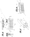
- Fillings 15 are attached between the profiles 5, 7 and 13, which prevent people from passing through and tools from falling down. Bars 17, aligned vertically or horizontally, or a grid or net 19 can be used as fillings 15.
- Fasteners 21 can be arranged on the first profile 5 on the left-hand side or on both sides.
- hinge elements 23 which can be attached to the fastening element 3 in a detachable and movable manner.
- the hinge elements 23 are directly connected to the fastening element 3.
- the hinge elements 23 are connected to the fastening element 3 in a vertically movable and lockable manner.
- the hinge elements 23 are arranged on clamps 25, which clamps 25 wrap around the tubular lower part 27 of the fastening element 3, e.g. a ceiling support. By loosening or tightening clamping elements such as screws 29, the clamps 25 and the hinge elements 23 attached thereto are moved vertically.
- the two clamps 25 can be connected to one another by a rod 31 running parallel to the lower tube 27 in order to enable synchronous displacement (rod shown in broken lines).
- one of the two clamping screws 29 can be dispensed with.
- the two hinge elements 23 can be attached to a casing tube which is arranged so as to be axially displaceable on the lower tube 27 of the fastening element 3.
- the casing tube (not shown) can be held at the desired height either by means of stopper elements such as bolts which penetrate the lower tube.
- stopper elements such as bolts which penetrate the lower tube.
- nuts can also be arranged on a thread arranged on the lower tube, with which the height of the casing tube and thus the hinges arranged therein can be continuously adjusted.
- the fastening element 3 comprises, in addition to the lower tube 27, a second upper tube 33, which can engage telescopically in the lower tube 27.
- the upper tube 33 can by means of an adjustment device 35 (not described in more detail) and thus the height of the fastening element can be determined.
- the fastening element 3 can be clamped between the floor and the ceiling of a room using the adjustment device 35.
- Support plates 37 can be attached to the ends of the lower tube 27 and the upper tube 33, on which pointed prongs 39 are formed.
- Bases 39 can be arranged on the support plates 37, which remain on the floor as lost elements in the coverings after the pouring of coverings, for example. This means that the height of the barrier elements 3 does not have to be adjusted when a covering or a slab covering is laid on the floor.
- Handles 51 are preferably arranged on the fastening elements 3, against which the extended locking element 1 comes into contact when the lift opening is closed and, if necessary, can be fastened or locked there with a U-lock on the second fastening element.
- Support surfaces 53 between the upper and lower hinge parts which are arranged at an angle of approximately 45° or are helically formed, ensure that the shut-off element 1 always rotates from the open position to the closed position and thus safely covers the opening cross-section of lift shaft openings.
- two essentially identical barrier elements 1 are connected to one another in a transversely movable manner by guide profiles 39 and sliding blocks 41 or rollers guided therein.
- the guide profiles 39 can be attached to the second, horizontally positioned profiles 7 or additionally to the profile 13 of the barrier element 1, or they themselves form the second profiles 7, which connect the two vertical first profiles 5 to one another.
- additional hinges can be arranged on the vertical profiles 5 of the barrier elements, with two upwardly directed hinge pins being attached to one side of the barrier element and Sleeves are attached to the profile on the opposite side at the appropriate height, the inner diameter of which corresponds to the diameter of the pins on the opposite side.
- the horizontal second profile 7 has a C-shaped cross-section, the laterally extending slot 7' of which is directed towards the second shut-off element.
- the second profile 7 consists of a rectangular profile. The latter is penetrated by a bolt 43, to the right-hand end of which a sliding block 41 is fastened.
- a nut 57 On the left-hand end there is a nut 57, preferably a self-locking nut.
- sliding blocks 41 with bolts 43 are arranged on the second profile 7 at the upper edge of the shut-off element and the same number on the lower second profile 7.
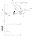
- the sliding block 41 can be arranged as in Figure 6 shown as a flat disc or flat rectangular plate.
- a A slotted nut 41 with a T-shaped cross-section can be provided, which engages wedge-like in the slot 7' on the profile 7 and partially fills the rest of the cross-section of the second profile 7 essentially completely.
- the slotted nut 41 slides along the edges on the slot 7', and not the bolt 43 as in Figure 6 shown.
- a ball bearing or a rotatably mounted disk can be mounted on the end of the bolt 43, which is guided in the C-shaped guide profile 39.
- two bolts 43 with sliding blocks 41 are arranged on the overlapping areas of the guide profiles 39 (when the shut-off elements 1 are pulled out) in order to prevent tilting when the shut-off elements 1 are pulled out or pushed together.
- locking screws 45 can be provided at the top and/or bottom or on a middle profile 13 to lock the two interacting shut-off elements 1.
- the bolt 43, which carries the sliding block 41 can also be axially displaceable and thus cause a locking between the two shut-off elements 1.
- the Figures 7 to 10 show a further embodiment of a guide arrangement 55.
- the upper second Profile 7 is made of two profiles with a mutual distance.
- the screw bolt 61 extends between the two profiles 7.
- the three screws 59 for example, can mesh with the corresponding threaded holes in the sliding bearing element 63 or be held there by means of screws.
- the sliding bearing element 63 therefore bears the load of the movable shut-off element and transfers it to the lower of the two profiles 7 arranged parallel and at a distance.
- the sliding bearing element 63 consists of a plastic material that slides well.
- the barrier element 1 can therefore be arranged as a pivoting door in front of a lift shaft opening.
- the fastening element 3 is first aligned exactly vertically on the side or inside the opening between the floor and ceiling of the building and clamped in place.
- a second fastening element 3 is clamped in the same way between the floor and ceiling on the right-hand side of the barrier element 3, and the door can now be hung.
- Locking part 47 serves, on the one hand, to lock a stop part 49 arranged on the right side of the shut-off element 1 positioned in the closed position.
- a lock can be attached to the locking part 47 and the stop part 49, which creates a lockable connection between the two parts.
- the locking part 47 is arranged on the fastening element 3 so that it can be moved vertically, e.g. on the rod 31 - if present - or on a clamp, in order to be able to lock the shut-off element 1 in any vertical position.
- the displaceability of the hinge part 23 on the fastening element 3 serves to lift the barrier element 1, for example, when a covering such as a coating or a slab covering is applied to the raw surface of the building floor.
- a toothed rail 65 similar to that used in rack railways, can be attached to the fastening element 3.
- This rail 65 makes it possible to insert the clamp 25 or the shaft of the screw 29 on the clamp 25 between two teeth of the toothed rod and thus to determine the height not by friction but by positive locking of the connection of the hinges to the fastening element 3.
- the barrier element 1 In another use of the barrier element 1, it can be used as a temporarily erected end wall to form a magazine.
- several barrier elements 1 and the associated fastening elements 3 are arranged between the floor and ceiling of the building, for example of a basement, and the gaps are closed by the barrier elements. In this way, the cordoned off area is accessible from all sides by opening or closing the corresponding barrier element 1.
Landscapes
- Engineering & Computer Science (AREA)
- Architecture (AREA)
- Mechanical Engineering (AREA)
- Civil Engineering (AREA)
- Structural Engineering (AREA)
- Conveying And Assembling Of Building Elements In Situ (AREA)
- Pressure Vessels And Lids Thereof (AREA)
- Operating, Guiding And Securing Of Roll- Type Closing Members (AREA)
- Specific Sealing Or Ventilating Devices For Doors And Windows (AREA)
Applications Claiming Priority (2)
| Application Number | Priority Date | Filing Date | Title |
|---|---|---|---|
| CH00034/20A CH717031A2 (de) | 2020-01-13 | 2020-01-13 | Transportables Absperrsystem zum Verschliessen von Öffnungen während der Bauphase und für die Erstellung von temporär benötigten Magazinbereichen in Neubauten. |
| EP21150451.9A EP3848321A3 (fr) | 2020-01-13 | 2021-01-07 | Système de barrière transportable permettant de fermer les ouvertures de cage d'ascenseur pendant la phase de construction et de créer des zones de magasinage temporairement requises dans les nouveaux bâtiments |
Related Parent Applications (1)
| Application Number | Title | Priority Date | Filing Date |
|---|---|---|---|
| EP21150451.9A Division EP3848321A3 (fr) | 2020-01-13 | 2021-01-07 | Système de barrière transportable permettant de fermer les ouvertures de cage d'ascenseur pendant la phase de construction et de créer des zones de magasinage temporairement requises dans les nouveaux bâtiments |
Publications (2)
| Publication Number | Publication Date |
|---|---|
| EP4350109A2 true EP4350109A2 (fr) | 2024-04-10 |
| EP4350109A3 EP4350109A3 (fr) | 2024-04-24 |
Family
ID=74105866
Family Applications (2)
| Application Number | Title | Priority Date | Filing Date |
|---|---|---|---|
| EP21150451.9A Withdrawn EP3848321A3 (fr) | 2020-01-13 | 2021-01-07 | Système de barrière transportable permettant de fermer les ouvertures de cage d'ascenseur pendant la phase de construction et de créer des zones de magasinage temporairement requises dans les nouveaux bâtiments |
| EP24159809.3A Pending EP4350109A3 (fr) | 2020-01-13 | 2021-01-07 | Système de fermeture transportable pour obturer des ouvertures de cage d'ascenseur pendant la phase de construction et pour créer des zones de magasin requises temporairement dans des constructions |
Family Applications Before (1)
| Application Number | Title | Priority Date | Filing Date |
|---|---|---|---|
| EP21150451.9A Withdrawn EP3848321A3 (fr) | 2020-01-13 | 2021-01-07 | Système de barrière transportable permettant de fermer les ouvertures de cage d'ascenseur pendant la phase de construction et de créer des zones de magasinage temporairement requises dans les nouveaux bâtiments |
Country Status (2)
| Country | Link |
|---|---|
| EP (2) | EP3848321A3 (fr) |
| CH (1) | CH717031A2 (fr) |
Citations (1)
| Publication number | Priority date | Publication date | Assignee | Title |
|---|---|---|---|---|
| CH700375A2 (de) | 2009-02-11 | 2010-08-13 | Maegert Bautechnik Ag | Anordnung zur Sicherung von Liftschachtöffnungen. |
Family Cites Families (10)
| Publication number | Priority date | Publication date | Assignee | Title |
|---|---|---|---|---|
| US3662993A (en) * | 1971-04-07 | 1972-05-16 | Anthony Lionetto | Protective guard fixture |
| JPH08240010A (ja) * | 1995-03-03 | 1996-09-17 | Maki Kogyo Kk | 垂直養生装置 |
| KR20010001357U (ko) * | 1999-06-28 | 2001-01-15 | 최문호 | 승강기 안전 작업난간대 |
| DE20203949U1 (de) * | 2002-03-12 | 2002-07-18 | Huang, Jian-Fa, Kaohsiung | Scharnier |
| US6976557B2 (en) * | 2004-02-27 | 2005-12-20 | Aluma Enterprises Inc. | Toeboard system for scaffolding |
| CA2515750C (fr) * | 2005-08-10 | 2014-06-03 | Jonathan Jonny Melic | Mecanisme de verrouillage et de levage pour poteau de support de cloture de protection |
| FR2927920B1 (fr) * | 2008-02-25 | 2012-07-13 | Nord Coffrage | Baie coulissante |
| GB2487505B (en) * | 2010-10-21 | 2012-12-12 | Znd Uk Ltd | Gate assembly |
| KR101744585B1 (ko) * | 2014-01-06 | 2017-06-08 | 주식회사 듀오텍 | 자동닫힘형 안전 게이트 |
| GB201601315D0 (en) * | 2016-01-25 | 2016-03-09 | Brand Energy & Infrastructure Services Uk Ltd | A safety screen |
-
2020
- 2020-01-13 CH CH00034/20A patent/CH717031A2/de unknown
-
2021
- 2021-01-07 EP EP21150451.9A patent/EP3848321A3/fr not_active Withdrawn
- 2021-01-07 EP EP24159809.3A patent/EP4350109A3/fr active Pending
Patent Citations (2)
| Publication number | Priority date | Publication date | Assignee | Title |
|---|---|---|---|---|
| CH700375A2 (de) | 2009-02-11 | 2010-08-13 | Maegert Bautechnik Ag | Anordnung zur Sicherung von Liftschachtöffnungen. |
| CH700375B1 (de) | 2009-02-11 | 2013-05-15 | Maegert Bautechnik Ag | Anordnung zur Sicherung von Liftschachtöffnungen. |
Also Published As
| Publication number | Publication date |
|---|---|
| EP4350109A3 (fr) | 2024-04-24 |
| EP3848321A3 (fr) | 2021-09-22 |
| CH717031A2 (de) | 2021-07-15 |
| EP3848321A2 (fr) | 2021-07-14 |
Similar Documents
| Publication | Publication Date | Title |
|---|---|---|
| DE60304219T2 (de) | Vorrichtung zum herstellen einer verschiebbaren wandkonstruktion | |
| EP3358107A1 (fr) | Collier de serrage pour coffrage | |
| DE102019107430A1 (de) | Anschlussleiste für Deckenschalungen | |
| AT518814A1 (de) | Zaunsystem sowie Montageverfahren für ein Zaunsystem | |
| EP2798133B1 (fr) | Panneau pour un système de coffrage de plafond et système de coffrage de plafond | |
| DE102004004883B4 (de) | Deckenschalungs-Paneel und System-Deckenschalung | |
| AT523944B1 (de) | Geländermodul | |
| EP3848321A2 (fr) | Système de barrière transportable permettant de fermer les ouvertures de cage d'ascenseur pendant la phase de construction et de créer des zones de magasinage temporairement requises dans les nouveaux bâtiments | |
| DE102013000105A1 (de) | Vorrichtung zur Verhinderung von Abstürzen | |
| AT396162B (de) | Auf baustellen verwendbare vorrichtung zum anbringen von gelaenderbrettern od. dgl. | |
| DE2407103A1 (de) | Eine arbeitsbuehne aufweisendes leitergeruest | |
| DE3331811A1 (de) | Geruestfeld, insbesondere fuer baustellen | |
| EP3211138A1 (fr) | Ossature porteuse pour un ouvrage | |
| DE102016111211A1 (de) | Schalungssystem für die Errichtung niedriger Bauabschnitte aus Ortbeton | |
| EP0851074B1 (fr) | Echafaudage pour plate-forme, charpente ou coffrage de dalle | |
| DE19636550C2 (de) | Bühnenbelag für Konsolbühnen oder Überbrückungsbühnen sowie Verfahren zur Montage einer Konsolbühne | |
| DE3048043A1 (de) | Schalungsstuetze | |
| DE2263371B2 (de) | Vorrichtung zum befestigen eines mindestens ein teil eines lichtschachtes bildenden betonfertigteils an einer gebaeudewand | |
| AT400467B (de) | Hilfsvorrichtung für den einsatz im bereich von fenster- oder durchgangsöffnungen sowie ecken bei der erstellung von aus einem mauerwerk gebildeten wänden | |
| EP3179002B1 (fr) | Habitation à superficie de base flexible | |
| WO2024017707A1 (fr) | Chaussure d'escalade, dispositif à cliquet, pièce de fixation et procédé | |
| DE19648988A1 (de) | Zerlegbares Fassadengerüst mit unter einem Winkel zueinander angeordneten Abschnitten | |
| EP0591629A1 (fr) | Méthode et dispositif pour le montage de panneaux de revêtement ou d'isolation | |
| WO2024208620A1 (fr) | Garde-corps pliable et son assemblage | |
| DE102022003723A1 (de) | Mauerlehre |
Legal Events
| Date | Code | Title | Description |
|---|---|---|---|
| PUAI | Public reference made under article 153(3) epc to a published international application that has entered the european phase |
Free format text: ORIGINAL CODE: 0009012 |
|
| STAA | Information on the status of an ep patent application or granted ep patent |
Free format text: STATUS: THE APPLICATION HAS BEEN PUBLISHED |
|
| REG | Reference to a national code |
Ref country code: DE Ref legal event code: R079 Free format text: PREVIOUS MAIN CLASS: E05F0001060000 Ipc: B66B0013300000 |
|
| PUAL | Search report despatched |
Free format text: ORIGINAL CODE: 0009013 |
|
| AC | Divisional application: reference to earlier application |
Ref document number: 3848321 Country of ref document: EP Kind code of ref document: P |
|
| AK | Designated contracting states |
Kind code of ref document: A2 Designated state(s): AL AT BE BG CH CY CZ DE DK EE ES FI FR GB GR HR HU IE IS IT LI LT LU LV MC MK MT NL NO PL PT RO RS SE SI SK SM TR |
|
| AK | Designated contracting states |
Kind code of ref document: A3 Designated state(s): AL AT BE BG CH CY CZ DE DK EE ES FI FR GB GR HR HU IE IS IT LI LT LU LV MC MK MT NL NO PL PT RO RS SE SI SK SM TR |
|
| RIC1 | Information provided on ipc code assigned before grant |
Ipc: E04G 25/00 20060101ALI20240320BHEP Ipc: E04G 5/14 20060101ALI20240320BHEP Ipc: E05F 1/06 20060101ALI20240320BHEP Ipc: E05D 5/10 20060101ALI20240320BHEP Ipc: E04G 25/04 20060101ALI20240320BHEP Ipc: E04G 21/32 20060101ALI20240320BHEP Ipc: B66B 13/30 20060101AFI20240320BHEP |
|
| STAA | Information on the status of an ep patent application or granted ep patent |
Free format text: STATUS: REQUEST FOR EXAMINATION WAS MADE |
|
| 17P | Request for examination filed |
Effective date: 20241023 |
|
| RBV | Designated contracting states (corrected) |
Designated state(s): AL AT BE BG CH CY CZ DE DK EE ES FI FR GB GR HR HU IE IS IT LI LT LU LV MC MK MT NL NO PL PT RO RS SE SI SK SM TR |
|
| STAA | Information on the status of an ep patent application or granted ep patent |
Free format text: STATUS: EXAMINATION IS IN PROGRESS |
|
| 17Q | First examination report despatched |
Effective date: 20241213 |
|
| GRAP | Despatch of communication of intention to grant a patent |
Free format text: ORIGINAL CODE: EPIDOSNIGR1 |
|
| STAA | Information on the status of an ep patent application or granted ep patent |
Free format text: STATUS: GRANT OF PATENT IS INTENDED |
|
| INTG | Intention to grant announced |
Effective date: 20260209 |