EP4357677A1 - Appareil de cuisson, de préférence avec fonction d'auto-nettoyage et/ou avec fonction d'auto-nettoyage. appareil combiné de cuisson à la vapeur de type four, de préférence avec fonction d'autonettoyage - Google Patents
Appareil de cuisson, de préférence avec fonction d'auto-nettoyage et/ou avec fonction d'auto-nettoyage. appareil combiné de cuisson à la vapeur de type four, de préférence avec fonction d'autonettoyage Download PDFInfo
- Publication number
- EP4357677A1 EP4357677A1 EP23197034.4A EP23197034A EP4357677A1 EP 4357677 A1 EP4357677 A1 EP 4357677A1 EP 23197034 A EP23197034 A EP 23197034A EP 4357677 A1 EP4357677 A1 EP 4357677A1
- Authority
- EP
- European Patent Office
- Prior art keywords
- cooking chamber
- sealing lip
- cooking
- closure element
- seal
- Prior art date
- Legal status (The legal status is an assumption and is not a legal conclusion. Google has not performed a legal analysis and makes no representation as to the accuracy of the status listed.)
- Pending
Links
- 238000010411 cooking Methods 0.000 title claims abstract description 318
- 238000004140 cleaning Methods 0.000 title claims abstract description 54
- 238000007789 sealing Methods 0.000 claims abstract description 139
- 239000000463 material Substances 0.000 claims description 41
- 230000007704 transition Effects 0.000 claims description 16
- 238000007373 indentation Methods 0.000 claims description 13
- 230000008719 thickening Effects 0.000 claims description 13
- 238000003780 insertion Methods 0.000 claims description 10
- 230000037431 insertion Effects 0.000 claims description 10
- 238000004519 manufacturing process Methods 0.000 claims description 6
- 239000007788 liquid Substances 0.000 description 23
- 238000009826 distribution Methods 0.000 description 15
- 230000000694 effects Effects 0.000 description 15
- XLYOFNOQVPJJNP-UHFFFAOYSA-N water Substances O XLYOFNOQVPJJNP-UHFFFAOYSA-N 0.000 description 15
- 239000012530 fluid Substances 0.000 description 8
- 238000009434 installation Methods 0.000 description 6
- 238000000034 method Methods 0.000 description 5
- 230000008569 process Effects 0.000 description 5
- 238000005452 bending Methods 0.000 description 3
- 239000012459 cleaning agent Substances 0.000 description 3
- 239000013013 elastic material Substances 0.000 description 3
- 230000007547 defect Effects 0.000 description 2
- 239000004744 fabric Substances 0.000 description 2
- 230000005484 gravity Effects 0.000 description 2
- 230000002787 reinforcement Effects 0.000 description 2
- 230000000007 visual effect Effects 0.000 description 2
- 230000009286 beneficial effect Effects 0.000 description 1
- 238000009835 boiling Methods 0.000 description 1
- 239000000356 contaminant Substances 0.000 description 1
- 230000001419 dependent effect Effects 0.000 description 1
- 238000011161 development Methods 0.000 description 1
- 230000018109 developmental process Effects 0.000 description 1
- 229920001971 elastomer Polymers 0.000 description 1
- 239000000806 elastomer Substances 0.000 description 1
- 239000013536 elastomeric material Substances 0.000 description 1
- 239000013505 freshwater Substances 0.000 description 1
- 230000005923 long-lasting effect Effects 0.000 description 1
- 239000000203 mixture Substances 0.000 description 1
- 230000003716 rejuvenation Effects 0.000 description 1
- 230000000717 retained effect Effects 0.000 description 1
- 238000007493 shaping process Methods 0.000 description 1
- 239000003351 stiffener Substances 0.000 description 1
- 230000003313 weakening effect Effects 0.000 description 1
Images



Classifications
-
- F—MECHANICAL ENGINEERING; LIGHTING; HEATING; WEAPONS; BLASTING
- F24—HEATING; RANGES; VENTILATING
- F24C—DOMESTIC STOVES OR RANGES ; DETAILS OF DOMESTIC STOVES OR RANGES, OF GENERAL APPLICATION
- F24C15/00—Details
- F24C15/02—Doors specially adapted for stoves or ranges
- F24C15/021—Doors specially adapted for stoves or ranges sealings for doors or transparent panel
Definitions
- the invention relates to a cooking appliance.
- the cooking appliance can preferably be a cooking appliance with a self-cleaning function and/or with a steam function.
- the cooking appliance can particularly preferably be an oven-steamer combination appliance, which preferably also has a self-cleaning function.
- Various kitchen appliances are known for preparing food, which can also be referred to as goods to be treated or as food to be cooked. These include hobs on which the food to be cooked in a cooking vessel such as a saucepan, with or without a lid, in a pan and the like can be cooked by boiling, frying and the like.
- the cooking vessel is placed on a hotplate on the hob and the base of the cooking vessel is heated electrically, inductively and the like by the hotplate.
- the cooking vessel can also be referred to as a cooking vessel, a food carrier or a food holder. In this case, the cooking vessel provides a cooking space for the food to be cooked, which in the case of pans and pots can be open or closed with a lid.
- Cooking devices are also known which have an immobile, i.e. fixed, cooking chamber formed with the cooking device, in which the food to be cooked can be placed in or on a cooking dish and cooked with the cooking chamber of the cooking device closed.
- a cooking device can be, for example, an oven, a steamer or a combination device consisting of an oven and a steamer.
- Such cooking devices with a fixed cooking chamber have in common that they have an outer housing as an outer casing, which essentially encloses the cooking device on the outside and protects its individual components and elements and makes them manageable together.
- An interior space is formed within the cooking device, which represents the cooking chamber and is essentially enclosed by an inner housing as an inner housing, also referred to as a cooking chamber muffle or muffle.
- a housing space is formed as an intermediate space, in which functional elements of the cooking device such as a control or a control unit, an electrical power supply and other components can be arranged which serve the intended use of the cooking appliance.
- the interior of the cooking appliance has a through opening in the depth to the front as an access opening, through which the interior of the cooking appliance is accessible to the user in order to insert cooking utensils into the interior of the cooking appliance as its cooking chamber and to arrange them there, as well as to take cooking utensils out of the interior of the cooking appliance after the food has been treated and to remove them from there.
- the access opening can be opened by the user by means of a closure element, for example in the form of a door that can be pivoted to the side, a flap that can be pivoted downwards and the like, in order to be able to access the interior of the cooking appliance, as described above, or to close the interior of the cooking appliance and carry out the cooking operation or the cooking process.
- a closure element can be designed to be closed or have a viewing window to allow the user to look into the closed interior of the cooking appliance.
- Such cooking appliances with a fixed cooking chamber are usually designed as built-in appliances or as built-in kitchen appliances in order to be arranged with their outer casing in a space-saving manner and at a height that is easily accessible for the user in the vertical direction in kitchen furniture such as in built-in cupboards in a kitchen and to be flush with the surfaces of the other cooking appliances, drawers, doors and the like of the kitchen furniture towards the front towards the user with their locking element, if necessary also with their panel, see above, which can improve the visual impression for the user.
- Such ovens, steamers and combination ovens and steamers usually need to be cleaned after use, particularly to remove residues from the previous cooking process from the cooking chamber.
- the inside casing of the cooking chamber is usually wiped down with water and cleaning agent using a cloth, sponge or similar, which can be a considerable effort for the user. This also means that not all areas, especially corners and the like, can be reached and cleaned with certainty.
- automatic cleaning functions are known, for example, in steam cookers and combination appliances consisting of ovens and steam cookers, in which a solution of water and cleaning agent as a cleaning solution is distributed in the cooking chamber by means of an automatic cleaning process.
- This process can be described as rinsing the cooking chamber with the solution or with the cleaning solution. This can relieve the user of this task.
- the cleaning solution can also reach areas of the cooking chamber that are difficult or impossible for the user to reach with a cloth, sponge or the like, which can improve the quality of cleaning.
- a further step in the automatic cleaning function can be a rinsing or clear rinse with plenty of clean water.
- tank appliances i.e. steam cookers or combination appliances with a removable water tank
- this can mean that the user has to remove, fill and insert the water tank at least once so that sufficient clear water can be used for rinsing or clear rinse.
- the amount of water can be adjusted as required and taken from the water pipe. However, this is only possible with these types of appliances.
- the corresponding liquids must be distributed by the cooking appliance in its cooking chamber in order to implement this kind of self-cleaning function.
- the cleaning liquid and the pure water can be distributed using the same distribution device, which usually extends from the ceiling of the cooking appliance into the cooking chamber and is designed to rotate about the vertical axis in order to ensure that the respective liquid is distributed as evenly as possible, so that as many areas of the cooking chamber as possible can be reached by the liquid, which can improve the respective effect.
- the EP 3 190 344 A1 describes a cooking appliance comprising a cooking chamber and a cleaning device for cleaning the cooking chamber.
- the cleaning device comprises a conveying device and a distribution device, wherein the conveying device comprises a pump arrangement with a pump device and wherein the distribution device has a rotatable distribution wheel and a motor device.
- the cooking chamber has a cooking chamber floor and a cooking chamber ceiling, wherein an outlet is provided in the cooking chamber floor and an inlet is provided in the cooking chamber ceiling.
- the conveying device is suitable and designed to convey a fluid from the outlet to the inlet.
- the distribution wheel is arranged below the inlet, so that the distribution wheel can be supplied with fluid through the inlet.
- the EP 3 715 723 A1 describes a cooking appliance comprising a cooking chamber, a distribution system for a cleaning liquid for cleaning the cooking chamber and a Circulation system for circulating the cleaning liquid with a pump, a drain line and an inlet line, wherein the pump is connected in a flow-conducting manner to a drain of the cooking chamber arranged in a cooking chamber floor of the cooking chamber by means of the drain line and is connected in a flow-conducting manner to an inlet opening of the distribution system by means of the inlet line, wherein the distribution system has a distribution disk with a pivot pin for connection, preferably for torque-transmitting connection, to a shaft of the cooking appliance.
- the EN 10 2020 108 023 A1 describes a cooking appliance, comprising a cooking chamber, a distribution system for a cleaning liquid for cleaning the cooking chamber and a circulation system for circulating the cleaning liquid with a pump, a drain line and an inlet line, wherein the pump is connected in a flow-conducting manner to a drain of the cooking chamber arranged in a cooking chamber floor of the cooking chamber by means of the drain line and is connected in a flow-conducting manner to an inlet opening of the distribution system by means of the inlet line, and wherein the distribution system has a distribution disk with a pivot pin for connection, preferably for torque-transmitting connection, to a shaft of the cooking appliance.
- a seal must be provided between the closure element and the inner housing, which can hold the liquids from the cooking appliance's self-cleaning function inside the cooking chamber so that they can be collected or drained away.
- This seal can also be referred to as a cooking chamber seal.
- Cooking chamber seals are from the publications DE 44 37 838 A1 , EP 2 336 643 A1 , DE 100 44 376 A1 as well as EP 1 923 638 A1 known.
- a cooking chamber seal is to ensure that the inner housing or its edge is sealed around the cooking chamber to the closure element, such as the appliance door. It should be noted that due to their extension around the inner housing or its edge, such seals have a relatively large or long sealing area, over the longitudinal extension of which the seal must be ensured.
- liquids can run down the inside of the closed closure element and thus hit a seal from above, which is located on the lower edge of the access opening between the inner housing and the closure element.
- Such liquids can also be distributed in the cooking chamber using a distributor wheel in such a way that they are sprayed directly onto the seal. This means that tightness must also be guaranteed in this regard.
- the cleaning fluids or cleaning solutions for such self-cleaning functions are a mixture of pure water and a cleaning agent, so that the cleaning solutions have a lower surface tension than pure water and can therefore be distributed more finely. This increases the requirements for tightness and the seal used.
- leaks can occur due to the tolerance chain between the inner housing or its edge, the seal and the closure element or its holder on the cooking appliance.
- the closure element cannot be positioned absolutely parallel to the cooking appliance, which can lead to leaks.
- the seal should therefore be able to cover as large a tolerance range as possible towards the inside of the closure element.
- the seal should also be guaranteed over the entire service life of the seal or cooking appliance. In particular, permanent deformations that occur during the service life should be avoided, as these affect the ability to compensate for tolerances on the inside of the closure element and can therefore lead to leaks. On the other hand, the seal should not be designed to be too stable, as the force applied to the inside of the closure element could then be too great and hinder or make it difficult to close, which could be perceived as a defect by the user.
- closure element in the area of the lower edge of the access opening, assembly can already be difficult if the closure element is designed as a flap with a pivot axis parallel to the lower edge of the access opening. Thickening or increasing the thickness of the seal could then make assembly very difficult or even impossible, at least in the area of the lower edge of the access opening.
- the requirements for the tightness of the cooking chamber seal in relation to the closure element also increase with the degree of steam saturation with which the cooking appliance is to be or can be operated, provided that the cooking appliance has a steam cooking function.
- the seal seals in a linear fashion rather than a flat area, i.e. that it forms a clear sealing line, which can improve the sealing effect of the cooking chamber seal.
- closure element does not close parallel to the inner housing or edge due to its ability to rotate using hinges or similar. This means that the seal or a sealing lip of the seal can stick to the inside of the closure element, fold in the wrong direction and, when closed again, lie in an unwanted orientation on the inside of the closure element, which can lead to leaks.
- the invention therefore poses the problem of providing a cooking appliance so that the fluid tightness of the access opening of the cooking chamber can be improved or ensured.
- This is to be achieved in particular in a cooking appliance with a self-cleaning function when using liquids, in particular when using cleaning liquids with reduced surface tension.
- This is to be achieved in particular in the area of the lower edge of the access opening of the cooking chamber.
- This is to be achieved in particular as long-lasting or durable as possible.
- no increased force should be exerted on the closure element, which could otherwise make closing more difficult.
- a linear seal should be able to be achieved.
- a desired alignment of the seal or a sealing lip of the seal with respect to the inside of the closure element should be ensured. In any case, this should be as simple, inexpensive, easy to install, space-saving and/or visually appealing or optically can be done inconspicuously for the user.
- At least an alternative to the known options should be created.
- the invention thus relates to a cooking appliance, preferably with a self-cleaning function and/or with a steam function, particularly preferably an oven-steamer combination appliance, preferably with a self-cleaning function, with a cooking chamber, which is formed in sections by an inner housing, and with a closure element which is designed and configured to close and open an access opening of the cooking chamber, wherein at least one cooking chamber seal is arranged facing the closure element, which is designed to lie fluid-tight against the inside of the closure element with a sealing lip for the closure element when the closure element is closed.
- the closure element can in particular be a door or a flap.
- the cooking chamber seal is arranged on the cooking appliance in such a way that the sealing effect can be achieved between the closure element in the closed state and the rest of the cooking appliance, in particular the inner housing and/or the front housing wall. This can ensure a fluid-tight seal of the closed closure element.
- the sealing lip extends sufficiently far from the inner housing to the closed closure element, preferably at least 8 mm, in order to compensate for manufacturing and/or assembly tolerances. This allows a larger area of the tolerance chain of the cooking chamber or inner housing, closure element and cooking chamber seal to be covered.
- the components of the closure element that are subject to tolerances can include, for example, the hinge, door and door lock. Providing an extension of the sealing lip of at least 8 mm can enable implementation for the usual applications.
- the sealing lip has a rounding, preferably with a radius of approximately 0.75 mm, in particular with a diameter in the range of 0.8 mm to 2 mm.
- the radius of the rounding is preferably greater than half the cross section of the sealing lip in the transition between the curvature and the rounding.
- the radius of the rounding is greater than the cross section of the sealing lip in the transition between the curvature and the rounding.
- the radius of the rounding is particularly preferably smaller than twice the largest cross section of the sealing lip in the region of the curvature.
- the rounded area which is also referred to as the head, has a cross-sectional shape that extends over at least half a circular arc on the side facing the closure element. This promotes linear contact with the closure element.
- the term circular arc is not strictly mathematical, but is intended to be colloquially understood as meaning that the rounded area extends over a larger angle of rotation.
- the head can have the cross-sectional shape of a circle, an egg, a lens or any convex shape.
- the rounding is designed to lie linearly against the closed closure element.
- the rounding or rounding can specifically ensure that the sealing lip is stiffened at the sealing edge of the sealing lip. This can also ensure that the sealing lip with its rounding does not lie flat against the closure element but in a linear manner, so that an effective or optimal seal can be ensured by the linear sealing surface. This can be implemented for the usual applications with a radius of approx. 0.75 mm. Dimensions that deviate from this are possible, as described above.
- the neck of the sealing lip extends from the head of the sealing lip towards the base body of the sealing element.
- the surfaces of the head and neck form an angle on at least one of the two sides of the cross-sectional profile that is greater than 90 degrees. This ensures that contact between the neck and the closure element is avoided.
- the transition can also be designed as an edge-free, flowing transition or have an angle greater than 180 degrees.
- the rounding of the sealing lip extends towards the closure element up to a vertical line which is aligned parallel to the closure element. This allows a notch to be created in the upper area of the sealing lip to limit the rounding in order to ensure that the closure element always rests against the reinforcement or the rounding of the sealing lip all the way around, even when the tolerance is compensated by the cooking chamber seal.
- part of the curve is limited in the direction of the inner housing by a perpendicular which passes through the intersection of the surfaces of the head and neck on the side of the sealing lip facing away from the inner housing.
- the head has an extension of at least 0.75 mm between the perpendicular and the distal end of the sealing lip, which faces the closure element.
- the rounding of the sealing lip facing the inner housing merges uniformly into the rest of the sealing lip.
- a homogeneous transition must be provided in the area of the sealing lip to prevent the stiffener from folding in the other direction.
- the sealing lip has a curvature facing the closure element.
- the curvature preferably has a radius of between approximately 3 mm and 10 mm, in particular with a radius of approximately 4 mm.
- the cross-section of the sealing lip in the area of the curvature varies from the indentation to the rounding, with the cross-section of the sealing lip in the area of the curvature being larger than in the transition between the curvature and the rounding and/or larger than in the area of the indentation.
- the sealing lip in the area of the curvature is convex on a side facing the door, preferably the sealing lip can be concave on a side facing the cooking chamber.
- the indentation in the transition between the sealing lip and the base body forms a joint which enables rotation of the sealing lip about an axis which is parallel to the longitudinal extension of the sealing element.
- the cross-section of the sealing lip in the region of the indentation is smaller than the diameter of the curve.
- the sealing lip facing the inner housing has a thickening, preferably with a radius of approximately 1.3 mm. This makes it possible to increase the thickness of the sealing lip for its service life, so that no significant permanent deformation away from the closure element occurs during this time, which could lead to reduced tightness.
- the cross-section of the sealing lip can be larger in the area of the thickening than in the transition between the curvature and the rounding and/or larger than in the area of the indentation.
- the cross-section of the Sealing lip in the area of the thickening is equal to or larger than the cross-section of the sealing lip in the area of the curvature.
- the sealing lip can be concavely formed in the region of the thickening on a side facing the door; preferably, the sealing lip can be convexly formed on a side facing the cooking chamber.
- the thickening is positioned closer to the indentation than the curvature and/or the curvature is positioned closer to the curve than the thickening.
- the sealing lip has an indentation, preferably with a radius of approximately 1 mm, at the transition to the rest of the cooking chamber seal.
- the indentation at this point can create a predetermined bending point for the sealing lip to ensure that the sealing lip moves in the desired direction. In particular, this ensures that the previously described thickening or thickening of the sealing lip does not lead to a greater introduction of force onto the closure element, which could hinder complete or fluid-tight closing of the closure element.
- the geometry also ensures that the thickness of the sealing lip remains constant, so that no thinner areas are susceptible to permanent deformation during the service life.
- the sealing lip can be designed to be concave in the region of the indentation on a side facing the door and on a side facing the cooking chamber.
- the curvature is particularly pronounced on the side facing the cooking chamber.
- the present invention also relates to a cooking appliance with a self-cleaning function, preferably with a steam function, particularly preferably an oven-steamer combination appliance, with a cooking chamber which is partially formed by an inner housing, with a cleaning device for cleaning the cooking chamber, wherein the cleaning device has a conveyor device and a distribution device, and with a closure element which is designed and configured to close and open an access opening of the cooking chamber, wherein at least one cooking chamber seal is arranged facing the closure element in a cooking chamber groove which is formed by the inner housing and/or by a front housing wall.
- the cleaning device can be implemented as described above or as known from the prior art.
- the cooking chamber seal has at least one material recess running along its essential extension direction, at least in sections, wherein the Material recess is designed to be open inwards in the assembly direction and/or outwards against the assembly direction.
- the assembly direction or its opposite direction points in the direction in which the closure element closes the access opening of the cooking chamber when closed. This can in particular be the longitudinal direction or the depth of the cooking appliance.
- the essential direction of extension of the cooking chamber seal which is preferably endlessly closed, is the course of the edge of the access opening of the cooking chamber.
- the cooking chamber seal can consist of several individual elements which are joined together to form the cooking chamber seal, whereby a continuous and one-piece design of the cooking chamber seal can be preferable to simplify assembly.
- the material recess can also be referred to as a notch or incision.
- the material recess can be formed directly during manufacture of the cooking chamber seal by appropriate shaping or can also be subsequently introduced into the cooking chamber seal by removing material.
- the cooking chamber seal according to the invention of the cooking appliance according to the invention has a material recess which extends in or against the assembly direction, in particular the longitudinal direction, from the outside into the material or into the body of the cooking chamber seal.
- This can bring about a positive and/or non-positive hold of the cooking chamber seal in the cooking chamber groove, which can improve the hold in the assembled state.
- Tolerance compensation can also be achieved by the deflection of the cooking chamber seal during assembly or when inserting it into the cooking chamber groove.
- the cooking chamber seal can be compressed more than previously known perpendicular to the assembly direction and perpendicular to the main extension direction due to the material recess, which can produce the effects and advantages described above. Furthermore, the material recess can have a beneficial effect on the structure of the cooking chamber seal.
- the material recess is designed to be open towards the outside, contrary to the mounting direction, and the material recess which is open on the outside is filled at least in sections by a clamping element in such a way that the cooking chamber seal is pressed against the sides of the cooking chamber groove perpendicular to the mounting direction.
- a clamping element in such a way that the cooking chamber seal is pressed against the sides of the cooking chamber groove perpendicular to the mounting direction.
- the cooking chamber seal can first be mounted in the cooking chamber groove and then pressed apart by the additional insertion of the clamping element perpendicular to the mounting direction and perpendicular to the essential extension direction, which can improve the sealing effect without changing or complicating the installation of the cooking chamber seal itself.
- the material recess that is open on the outside is only formed along a lower edge of the inner housing and the clamping element is arranged exactly along the lower edge of the inner housing.
- the material recess that is open on the outside has a constriction perpendicular to the assembly direction
- the clamping element has a clamping edge and a taper that is thinner than the clamping edge perpendicular to the assembly direction, and wherein the clamping element is held in a form-fitting manner by the constriction of the material recess that is open on the outside by means of the clamping edge.
- an additional force-fitting hold can also be achieved.
- the clamping element can be held by the cooking chamber seal without any further measures, which can keep the implementation effort low and simplify assembly.
- a secure hold can also be achieved in this way, so that the clamping element cannot be accidentally removed from the cooking chamber seal by the user, even when cleaning or wiping the outer surface of the cooking chamber seal.
- the material recess of the cooking chamber seal which is open on the outside, has a recess in the assembly direction facing the closure element on at least one side, preferably on both sides, wherein the clamping element facing the closure element has a recess on at least one side, preferably on both sides on both sides, has an outer edge which is partially or completely received in the assembly direction by the corresponding recess of the cooking chamber seal.
- the clamping element can be received within the contour of the cooking chamber seal or its recess as a clamping element receptacle so as not to protrude towards the closure element, which could impair the sealing effect of the cooking chamber seal and/or be perceived by the user as visually disturbing.
- a front surface of the clamping element facing the closure element is set back from the cooking chamber seal. This can ensure that the clamping element can be prevented from protruding towards the closure element, even within the scope of manufacturing and assembly tolerances.
- the cooking chamber seal and a front surface of the clamping element facing the closure element together form a smooth surface. This can enable a smooth finish towards the closure element, which the user may find particularly visually appealing.
- the material recess is designed to be open towards the inside in the assembly direction and the material recess that is open on the inside is designed to be continuous along the essential extension direction of the cooking chamber seal.
- This can represent an alternative possibility for the specific implementation.
- This can also simplify implementation because the material recess can be introduced into the material of the cooking chamber seal from the inside when viewed in the assembled state, which can keep the depth of the material recess low. This also allows the cooking chamber seal to be closed, flat or smooth towards the closure element, which can improve the visual appearance for the user.
- the cooking chamber seal is designed to be flush with the surface opposite the material recess that is open on the inside. This can be perceived by the user as visually appealing. This can also promote the sealing effect with respect to the closure element.
- the cooking chamber seal has a sealing lip for the front housing wall, which rests against the front housing wall in the assembly direction. This can improve the sealing effect at this point.
- the cooking chamber seal has a grooved contact surface which rests against the front housing wall perpendicular to the mounting direction.
- the grooved contact surface is a part of the insertion section
- the grooved contact surface enables a point-by-point contact surface that is as uniform as possible, perpendicular to the installation direction and perpendicular to the main extension direction, which can improve the sealing effect.
- the cooking chamber seal has a sealing lip for an inner side of the cooking chamber, which lip rests on the inner side of the cooking chamber perpendicular to the assembly direction. This can improve the sealing effect at this point.
- the cooking chamber seal is made in one piece and/or from an elastic material.
- the one-piece, i.e. integral, design of the cooking chamber seal from one piece can simplify production and assembly.
- the use of an elastic material, such as in particular an elastomer material, can ensure or improve the sealing effect.
- the present invention also relates to a cooking chamber seal for use in a cooking appliance as described above.
- a cooking chamber seal as described above can thus be provided in order to implement a cooking appliance with a self-cleaning function as described above and to be able to use its properties and advantages.
- the present invention further relates to a clamping element for use in a cooking chamber seal as described above.
- a clamping element as described above can thus be provided in order to implement a cooking chamber seal as described above and to be able to use its properties and advantages.
- the aim of the invention is to extend the service life of a sealing lip on a cooking chamber seal.
- a more stable sealing lip should not exert any greater force on the appliance door than before.
- the appliance doors should still be able to be closed completely.
- a linear seal should be ensured, since leaks can occur when sealing over a larger area during a cooking or cleaning process.
- the appliance doors do not close in parallel due to the hinges usually positioned at the bottom of the appliance. The sealing lip can therefore stick to the inside of the appliance door and fold down in the wrong direction, which can also be taken into account with the new lip geometry.
- the sealing lip can be extended for better tolerance compensation.
- a rounded end of the sealing lip can ensure that the appliance door is in line and not sealed over a flat surface.
- a total thickening of the sealing lip can serve to improve the service life, whereby a Parallel notches can ensure that the force applied to the door is not too great.
- the sealing lip can also not be straight, but have a clear overall curvature so that the direction of deformation of the sealing lip is specified.
- the sealing function can be significantly improved according to the invention without the need for additional sealing lips between which contaminants collect and which can be difficult to clean.
- the function can be performed by one component without the need for a second seal.
- the entire sealing area can be defined more clearly and errors such as leaks through a flat seal or the seal folding over in the wrong direction can be prevented. Compared to the state of the art, a greater tolerance compensation can be ensured by the sealing lip and the service life can be increased.
- the above figures are viewed in Cartesian coordinates.
- a longitudinal direction X which can also be referred to as depth X or length X.
- a transverse direction Y Perpendicular to the longitudinal direction X there is a transverse direction Y, which can also be referred to as width Y.
- a vertical direction Z Perpendicular to both the longitudinal direction X and the transverse direction Y there is a vertical direction Z, which can also be referred to as height Z and corresponds to the direction of gravity.
- the longitudinal direction X and the transverse direction Y together form the horizontal X, Y, which can also be referred to as the horizontal plane X, Y.
- a cooking appliance 1 according to the invention with a self-cleaning function is considered as a cooking appliance 1 with a self-cleaning function and with a steam function using the example of an oven-steamer combination appliance 1 with a self-cleaning function.
- the oven-steamer combination device 1 has a cooking chamber 10 as interior space 10, which is formed by an inner housing 11 as inner housing 11.
- the side of the inner housing 11 facing the cooking chamber 10 can be referred to as the cooking chamber interior 11a and the side of the inner housing 11 facing away from the cooking chamber 10 can be referred to as the cooking chamber exterior 11b.
- the cooking chamber 10 is accessible in the longitudinal direction X towards the front to a user through an access opening 14, wherein the access opening 14 can be opened and closed by means of a closure element (not shown), see e.g. Figure 1 .
- the inner housing 11 is adjoined in the transverse direction Y and in the vertical direction Z by a front housing wall 13, which limits or closes off a gap (not designated) in the longitudinal direction X towards the front. Between the edge of the inner housing 11 and the front housing wall 13, a cooking chamber groove 12 is formed as a recess in the longitudinal direction X into the cooking appliance and running parallel to the cooking chamber 10, see e.g. Figure 2 .
- a cooking chamber seal 2 is used according to the first embodiment, which is made in one piece from an elastic material and in particular from an elastomeric material.
- the cooking chamber seal 2 has a preferred direction of extension in which the cooking chamber seal 2 is endlessly closed.
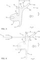
- the cross section of the profile of the cooking chamber seal 2 according to the first embodiment is, for example, the Figure 3
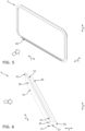
- the cooking chamber seal 2 is rectangular with rounded corners so that as it corresponds to the shape of the cooking chamber groove 12 of the oven-steam cooker combination appliance 1, cf. Figure 5 of the second embodiment.
- the cooking chamber seal 2 is mounted in an assembly direction A, which corresponds to the longitudinal direction X and points away from the user into the cooking chamber groove 12 of the oven-steam cooker combination device 1.
- the cooking chamber seal 2 has a housing holder receptacle 20 in the form of a recess, with which the cooking chamber seal 2 is held in a form-fitting manner around an edge of the inner housing 11, see e.g. Figures 3 and 4 .
- the cooking chamber seal 2 has a grooved contact surface 24, which rests perpendicular to the mounting direction A on the front housing wall 13, see e.g. Figures 3 and 4 This makes it possible to create a contact surface that is as uniform as possible at this point.
- the cooking chamber seal 2 according to the first embodiment has a sealing lip 21 for the front housing wall 13, which rests against the front housing wall 13 in the mounting direction A, see e.g. Figures 3 and 4 This allows fluid tightness to be achieved at this point.
- the cooking chamber seal 2 has a sealing lip 22 for the closure element, which is designed to rest against the inside of the closure element against the mounting direction A, see e.g. Figures 3 and 4 .
- This allows fluid tightness to be achieved at this point.
- the sealing lip 22 extends sufficiently far from the inner housing 11 towards the closed closure element in order to compensate for manufacturing and/or assembly tolerances. This can improve the tolerance compensation compared to the closed closure element.
- an extension B of approx. 8 mm can be achieved, see e.g. Figures 3 and 9
- the extension B is selected in a range between 5 mm and 20 mm.
- the sealing lip 22 has a rounding 22a, preferably with a radius of approximately 0.75 mm, so that the sealing lip 22 with its rounding 22a rests linearly against the closed closure element, which can improve the tightness.
- the rounding 22a of the sealing lip 22 extends towards the closure element up to a vertical which is aligned parallel to the closure element. This allows a notch (not designated) to be created between the rounding 22a of the sealing lip 22 and the rest of the sealing lip 22 to ensure that the force introduced by the sealing lip 22 onto the closed closure element does not become too great, as this could hinder the closure of the closure element and lead to leaks there.
- the curve 22a of the sealing lip 22 facing the inner housing 11 merges uniformly into the rest of the sealing lip 22.
- the sealing lip 22 has a curvature 22b facing the closure element, preferably with a radius of approximately 4 mm. This allows for reinforcement facing the closure element, which can prevent the sealing lip 22 from bending towards the closure element.
- a thickening 22c preferably with a radius of approximately 1.3 mm, is located opposite and thus facing the inner housing 11, so that thinner areas of the sealing lip 22 can be avoided, which could be susceptible to permanent deformation during its service life.
- the sealing lip 22 has an indentation 22d, preferably with a radius of approximately 1 mm, at the transition to the rest of the cooking chamber seal 2. This primarily serves to reduce the force introduced onto the door by the thicker sealing lip 22.
- the indentation 22d can be used to specify a preferred bending direction towards the inner housing.
- the indentation can be arranged in particular on a side of the cooking chamber seal 2 facing the cooking chamber or a side facing away from the door.
- the cooking chamber seal 2 according to the first embodiment has a sealing lip 23 for the cooking chamber inner side 11a of the cooking chamber 11, which rests perpendicularly to the mounting direction A on the cooking chamber inner side 11a of the cooking chamber 11, see e.g. Figures 3 and 4 This allows fluid tightness to be achieved at this point.
- the cooking chamber seal 2 has a material recess 25 which is open inwards in the assembly direction A, ie points inwards into the cooking chamber groove 12, see e.g. Figures 3 and 4 , and thus increases the elasticity of this area of the cooking chamber seal 2 perpendicular to the installation direction A and perpendicular to the essential direction of extension of the cooking chamber seal 2. This can simplify installation and enable tolerance compensation.
- the material recess 25, which is open on the inside and can also be referred to as a notch 25, is designed to be continuous along the essential direction of extension of the cooking chamber seal 2.
- the cooking chamber seal 2 is designed to be flush with the surface opposite the material recess 25, which is open on the inside, in order to enable a smooth finish compared to the closed closure element.
- the cooking chamber seal 2 according to the second embodiment of the Figures 5 to 8 is used in combination with a one-piece clamping element 3 or a clamping piece 3 used.
- the cooking chamber seal 2 according to the second embodiment corresponds to the cooking chamber seal 2 according to the first embodiment with the difference that instead of the circumferential material recess 25 open on the inside, only in the area of the lower edge of the cooking chamber 10 there is a material recess 26 open to the outside, i.e. a material recess 26 open on the outside, in the form of a clamping element holder 26, which is open against the assembly direction A.
- the clamping element holder 26 of the cooking chamber seal 2 merges into a constriction 26a along the longitudinal direction X. In the vertical direction Z above and below the constriction 26a a recess 26b is formed, see e.g. Figure 7 .
- the clamping element 3 has a clamping edge 32, which is designed in the shape of a ball head in cross section and is received in the assembled state by the clamping element holder 26 of the cooking chamber seal 2. From the clamping edge 32, the clamping element 3 passes into a taper 31, which in the assembled state is received by the constriction 26a of the cooking chamber seal 2. In the vertical direction Z, an outer edge 31 is formed above and below the taper 31, see e.g. Figure 6 , which in the assembled state fill the recesses 26b of the cooking chamber seal 26, so that a front surface 30 of the clamping element 3 is flush with the cooking chamber seal 2 towards the closed closure element, see e.g. Figure 8 .
- the cooking chamber seal 2 When assembling the cooking chamber seal 2 according to the second embodiment, as in the first embodiment, the cooking chamber seal 2 is inserted by hand into the cooking chamber groove 12 and is pressed into the cooking chamber groove 12 of the oven-steamer combination device 1 in such a spring-elastic manner that the cooking chamber seal 2 is held in a form-fitting manner around the corresponding edge of the inner housing 11 by means of the cooking device housing holder 20. In both cases, this can be facilitated by the material recess 25 open on the inside in the first embodiment or by the material recess 26b open on the outside in the second embodiment.
- the clamping element 3 is then pressed with the clamping edge 32 first in the assembly direction A into the material recess 26 open on the outside as a clamping element receptacle 26, whereby the tightness is increased in particular in the area of the cooking appliance housing receptacle 20 and the corresponding edge of the inner housing 11.
- the clamping element 3 is held in a form-fitting manner by the cooking chamber seal 2 by means of the constriction 26a of the cooking chamber seal 2.
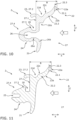
- the Figure 10 equals to Figure 7 , supplemented by some further information.
- the Figure 11 equals to Figure 3 , supplemented by some further information.
- Both Figures 10 and 11 show a cooking chamber seal 2 for use in a cooking appliance 1 as already described above.
- the cooking chamber seal 2 comprises a sealing lip 21 for contact with the front housing wall 13 and a sealing lip 22 for contact with the closure element and a base body 27 for fastening the cooking chamber seal 2 to the cooking appliance 1.
- the base body 27 has a contact surface 27.1 for contact with a vertical section of the front housing wall 13.
- the base body 27 has an insertion section 27.4 for insertion into a cooking chamber groove 12 of the cooking appliance 1.
- the base body 27 has a material recess 25, 26 which is open perpendicular to the preferably flat contact surface 27.1.
- the contact surface 27.1 is delimited by at least one holding element 27.2, 27.3, in particular wherein the one holding element 27.2 is provided as a sealing lip 23 for contact with the cooking chamber interior 11a and/or wherein the one holding element 27.3 is designed as a part of the insertion section 27.4.
- the holding elements 27.2, 27.3 interact with the housing of the cooking appliance 1 in a force-fitting and/or form-fitting manner, in particular as latching hooks.
- the sealing lip 22 has a neck 22.2 which extends from the head 22.1 of the sealing lip 22 in the direction of the base body 27 of the sealing element 2.
- the surfaces of the head 22.1 and the neck 22.2 form an angle on at least one of the two sides of the cross-sectional profile which is greater than 90 degrees.
- the transition can also be designed as an edge-free, flowing transition or have an angle greater than 180 degrees.
- the part of the head 22.1 or the curve 22a which faces the closure element is limited in the direction of the inner housing 11 by a vertical 22.3.
- the vertical 22.3 passes through the intersection point of the surfaces of the head 22.1 and the neck 22.2 on the side of the sealing lip 22 facing away from the inner housing 11.
- the head 22.1 preferably has an extension of at least 0.75 mm between the vertical 22.3 and the distal end of the sealing lip (22) which faces the closure element.
Landscapes
- Engineering & Computer Science (AREA)
- Chemical & Material Sciences (AREA)
- Combustion & Propulsion (AREA)
- Mechanical Engineering (AREA)
- General Engineering & Computer Science (AREA)
- Cookers (AREA)
Applications Claiming Priority (1)
| Application Number | Priority Date | Filing Date | Title |
|---|---|---|---|
| BE20225837A BE1030966B1 (de) | 2022-10-18 | 2022-10-18 | Gargerät, vorzugsweise mit Selbstreinigungsfunktion und bzw. oder mit Dampfunktion, besonders vorzugsweise Backofen-Dampfgarer-Kombigerät, vorzugsweise mit Selbstreinigungsfunktion |
Publications (1)
| Publication Number | Publication Date |
|---|---|
| EP4357677A1 true EP4357677A1 (fr) | 2024-04-24 |
Family
ID=85321207
Family Applications (1)
| Application Number | Title | Priority Date | Filing Date |
|---|---|---|---|
| EP23197034.4A Pending EP4357677A1 (fr) | 2022-10-18 | 2023-09-13 | Appareil de cuisson, de préférence avec fonction d'auto-nettoyage et/ou avec fonction d'auto-nettoyage. appareil combiné de cuisson à la vapeur de type four, de préférence avec fonction d'autonettoyage |
Country Status (2)
| Country | Link |
|---|---|
| EP (1) | EP4357677A1 (fr) |
| BE (1) | BE1030966B1 (fr) |
Cited By (1)
| Publication number | Priority date | Publication date | Assignee | Title |
|---|---|---|---|---|
| WO2026051332A1 (fr) * | 2024-09-06 | 2026-03-12 | 佛山市顺德区美的电热电器制造有限公司 | Bague d'étanchéité et appareil de cuisson |
Citations (15)
| Publication number | Priority date | Publication date | Assignee | Title |
|---|---|---|---|---|
| DE2929837B1 (de) * | 1979-07-23 | 1981-01-15 | Donges Stahlbau Gmbh | Schlauchfoermige Kantenleiste fuer kraftbetriebene Torfluegel o.dgl. |
| DE9106182U1 (de) * | 1991-05-18 | 1991-07-25 | Technoprofil Breidenbach & Blau GmbH & Co. KG, 42327 Wuppertal | Strangförmige Klemmdichtung |
| EP0570269A1 (fr) * | 1992-05-15 | 1993-11-18 | Hutchinson | Garniture d'étancheité pour menuiserie en PVC ou matériau semblable et menuiserie incorportant une telle garniture comme une fenêtre, porte-fenêtre ou analogue |
| DE4437838A1 (de) | 1994-10-22 | 1996-04-25 | Heerig Hans Walter | Wärmebehandlungsgerät |
| DE29609162U1 (de) * | 1996-05-22 | 1996-07-11 | Eisele, Oliver, 64732 Bad König | Strangförmige Dichtung |
| EP0726423A2 (fr) * | 1995-02-10 | 1996-08-14 | REHAU AG + Co | Joint d'étanchéité pour four de cuisson |
| EP0992740A1 (fr) * | 1998-10-07 | 2000-04-12 | POSA S.p.A. | Joint d'étancheité en élastomère pour four de cuisson |
| DE10044376A1 (de) | 2000-09-08 | 2002-04-04 | Aeg Hausgeraete Gmbh | Backgerät |
| US20020104276A1 (en) * | 2000-10-24 | 2002-08-08 | Joseph Lucas | Seal for fixed window of motor vehicle with curved concave corners |
| EP1923638A1 (fr) | 2005-09-08 | 2008-05-21 | Sharp Kabushiki Kaisha | Dispositif de cuisson |
| EP1676973B1 (fr) * | 2004-12-29 | 2010-04-28 | HÜBNER GmbH | Profilé de porte entre le battant d'une porte et la paroi d'un compartiment |
| EP2336643A2 (fr) | 2009-12-21 | 2011-06-22 | BSH Bosch und Siemens Hausgeräte GmbH | Appareil ménager |
| EP3190344A1 (fr) | 2016-01-06 | 2017-07-12 | Miele & Cie. KG | Appareil de cuisson |
| EP3715723A1 (fr) | 2019-03-26 | 2020-09-30 | Miele & Cie. KG | Disque de distribution pour un liquide de nettoyage, système de distribution, appareil de cuisson doté d'une chambre de cuisson et son procédé de nettoyage |
| DE102020108023A1 (de) | 2020-03-24 | 2021-09-30 | Miele & Cie. Kg | Verteilerscheibe für eine Reinigungsflüssigkeit, Verteilersystem, Gargerät mit einem Garraum und Verfahren zu dessen Reinigung |
Family Cites Families (3)
| Publication number | Priority date | Publication date | Assignee | Title |
|---|---|---|---|---|
| FR2584975B1 (fr) * | 1985-07-19 | 1987-11-20 | Hutchinson | Procede d'obtention par co-extrusion de profiles comprenant au moins deux parties ayant des proprietes differentes et profiles ainsi obtenus |
| DE102004039432A1 (de) * | 2004-08-13 | 2006-02-23 | BSH Bosch und Siemens Hausgeräte GmbH | Gargerättürdichtung |
| DE102012112805A1 (de) * | 2012-12-20 | 2014-06-26 | Miele & Cie. Kg | Gargerät |
-
2022
- 2022-10-18 BE BE20225837A patent/BE1030966B1/de active IP Right Grant
-
2023
- 2023-09-13 EP EP23197034.4A patent/EP4357677A1/fr active Pending
Patent Citations (15)
| Publication number | Priority date | Publication date | Assignee | Title |
|---|---|---|---|---|
| DE2929837B1 (de) * | 1979-07-23 | 1981-01-15 | Donges Stahlbau Gmbh | Schlauchfoermige Kantenleiste fuer kraftbetriebene Torfluegel o.dgl. |
| DE9106182U1 (de) * | 1991-05-18 | 1991-07-25 | Technoprofil Breidenbach & Blau GmbH & Co. KG, 42327 Wuppertal | Strangförmige Klemmdichtung |
| EP0570269A1 (fr) * | 1992-05-15 | 1993-11-18 | Hutchinson | Garniture d'étancheité pour menuiserie en PVC ou matériau semblable et menuiserie incorportant une telle garniture comme une fenêtre, porte-fenêtre ou analogue |
| DE4437838A1 (de) | 1994-10-22 | 1996-04-25 | Heerig Hans Walter | Wärmebehandlungsgerät |
| EP0726423A2 (fr) * | 1995-02-10 | 1996-08-14 | REHAU AG + Co | Joint d'étanchéité pour four de cuisson |
| DE29609162U1 (de) * | 1996-05-22 | 1996-07-11 | Eisele, Oliver, 64732 Bad König | Strangförmige Dichtung |
| EP0992740A1 (fr) * | 1998-10-07 | 2000-04-12 | POSA S.p.A. | Joint d'étancheité en élastomère pour four de cuisson |
| DE10044376A1 (de) | 2000-09-08 | 2002-04-04 | Aeg Hausgeraete Gmbh | Backgerät |
| US20020104276A1 (en) * | 2000-10-24 | 2002-08-08 | Joseph Lucas | Seal for fixed window of motor vehicle with curved concave corners |
| EP1676973B1 (fr) * | 2004-12-29 | 2010-04-28 | HÜBNER GmbH | Profilé de porte entre le battant d'une porte et la paroi d'un compartiment |
| EP1923638A1 (fr) | 2005-09-08 | 2008-05-21 | Sharp Kabushiki Kaisha | Dispositif de cuisson |
| EP2336643A2 (fr) | 2009-12-21 | 2011-06-22 | BSH Bosch und Siemens Hausgeräte GmbH | Appareil ménager |
| EP3190344A1 (fr) | 2016-01-06 | 2017-07-12 | Miele & Cie. KG | Appareil de cuisson |
| EP3715723A1 (fr) | 2019-03-26 | 2020-09-30 | Miele & Cie. KG | Disque de distribution pour un liquide de nettoyage, système de distribution, appareil de cuisson doté d'une chambre de cuisson et son procédé de nettoyage |
| DE102020108023A1 (de) | 2020-03-24 | 2021-09-30 | Miele & Cie. Kg | Verteilerscheibe für eine Reinigungsflüssigkeit, Verteilersystem, Gargerät mit einem Garraum und Verfahren zu dessen Reinigung |
Cited By (1)
| Publication number | Priority date | Publication date | Assignee | Title |
|---|---|---|---|---|
| WO2026051332A1 (fr) * | 2024-09-06 | 2026-03-12 | 佛山市顺德区美的电热电器制造有限公司 | Bague d'étanchéité et appareil de cuisson |
Also Published As
| Publication number | Publication date |
|---|---|
| BE1030966A1 (de) | 2024-05-15 |
| BE1030966B1 (de) | 2024-05-21 |
Similar Documents
| Publication | Publication Date | Title |
|---|---|---|
| DE602004007867T2 (de) | Kochgerät | |
| EP1918644B2 (fr) | Porte pour un appareil de cuisson et apparail de cuisson | |
| EP4357677A1 (fr) | Appareil de cuisson, de préférence avec fonction d'auto-nettoyage et/ou avec fonction d'auto-nettoyage. appareil combiné de cuisson à la vapeur de type four, de préférence avec fonction d'autonettoyage | |
| DE10156419B4 (de) | Gargerät mit Kondensatsammelrinne | |
| DE102023119441A1 (de) | Gargerät mit Selbstreinigungsfunktion, vorzugsweise mit Dampffunktion, besonders vorzugsweise Backofen-Dampfgarer-Kombigerät | |
| DE202005016735U1 (de) | Geschirrspülmaschine | |
| BE1030780B1 (de) | Gargerät mit Selbstreinigungsfunktion, vorzugsweise mit Dampfunktion, besonders vorzugsweise Backofen-Dampfgarer-Kombigerät | |
| EP3045820B1 (fr) | Joint de porte pour appareil de cuisson et appareil de cuisson | |
| DE4032490C1 (en) | Seal on door frame - acts as condensate trap when door on kitchen steamer is open | |
| DE4437838C2 (de) | Wärmebehandlungsgerät mit einer eine Beschickungsöffnung umgebenden Dichtung | |
| WO2023217582A1 (fr) | Dispositif de cuisson et procédé d'ouverture | |
| EP4374746A1 (fr) | Appareil de cuisine | |
| DE102013106623B4 (de) | Gargerät mit Abweiser | |
| EP3410018A1 (fr) | Appareil de cuisine | |
| BE1030783B1 (de) | Gargerät, vorzugweise mit Dampfunktion, besonders vorzugsweise Backofen-Dampfgarer-Kombigerät, mit Selbstreinigungsfunktion | |
| EP2789920B1 (fr) | Séparateur d'espace de cuisson pour un appareil de cuisson et appareil de cuisson doté d'un tel séparateur d'espace de cuisson | |
| DE102018128475A1 (de) | Küchengerät | |
| DE102010031547B4 (de) | Haushaltsgerät | |
| EP3202291B1 (fr) | Appareil de cuisson et dispositif d'écoulement associé | |
| DE102015102981A1 (de) | Frontblech für ein Gargerät, Baugruppe mit einem Frontblech und einem Gargeräte-Innenkasten sowie Verfahren zur Herstellung der Baugruppe | |
| EP4335330B1 (fr) | Appareil de cuisson industriel | |
| DE19913577B4 (de) | Türsteuerung für eine Geschirrspülmaschine | |
| DE102022123067B3 (de) | Gewerbliches Gargerät | |
| DE202016000739U1 (de) | Gargeräteabfluss mit rotierendem Abflussstöpsel | |
| DE102024104992A1 (de) | Gerätetür für ein Reinigungsgerät und Reinigungsgerät |
Legal Events
| Date | Code | Title | Description |
|---|---|---|---|
| PUAI | Public reference made under article 153(3) epc to a published international application that has entered the european phase |
Free format text: ORIGINAL CODE: 0009012 |
|
| STAA | Information on the status of an ep patent application or granted ep patent |
Free format text: STATUS: THE APPLICATION HAS BEEN PUBLISHED |
|
| AK | Designated contracting states |
Kind code of ref document: A1 Designated state(s): AL AT BE BG CH CY CZ DE DK EE ES FI FR GB GR HR HU IE IS IT LI LT LU LV MC ME MK MT NL NO PL PT RO RS SE SI SK SM TR |
|
| STAA | Information on the status of an ep patent application or granted ep patent |
Free format text: STATUS: REQUEST FOR EXAMINATION WAS MADE |
|
| 17P | Request for examination filed |
Effective date: 20241024 |
|
| RBV | Designated contracting states (corrected) |
Designated state(s): AL AT BE BG CH CY CZ DE DK EE ES FI FR GB GR HR HU IE IS IT LI LT LU LV MC ME MK MT NL NO PL PT RO RS SE SI SK SM TR |