EP4371707A1 - Ensemble d'actionnement de pince, pince et procédé d'assemblage - Google Patents
Ensemble d'actionnement de pince, pince et procédé d'assemblage Download PDFInfo
- Publication number
- EP4371707A1 EP4371707A1 EP22207566.5A EP22207566A EP4371707A1 EP 4371707 A1 EP4371707 A1 EP 4371707A1 EP 22207566 A EP22207566 A EP 22207566A EP 4371707 A1 EP4371707 A1 EP 4371707A1
- Authority
- EP
- European Patent Office
- Prior art keywords
- hand lever
- lever plate
- pliers
- hand
- longitudinal section
- Prior art date
- Legal status (The legal status is an assumption and is not a legal conclusion. Google has not performed a legal analysis and makes no representation as to the accuracy of the status listed.)
- Granted
Links
Images












Classifications
-
- B—PERFORMING OPERATIONS; TRANSPORTING
- B25—HAND TOOLS; PORTABLE POWER-DRIVEN TOOLS; MANIPULATORS
- B25B—TOOLS OR BENCH DEVICES NOT OTHERWISE PROVIDED FOR, FOR FASTENING, CONNECTING, DISENGAGING, OR HOLDING
- B25B27/00—Hand tools, specially adapted for fitting together or separating parts or objects whether or not involving some deformation, not otherwise provided for
- B25B27/14—Hand tools, specially adapted for fitting together or separating parts or objects whether or not involving some deformation, not otherwise provided for for assembling objects other than by press fit or detaching same
- B25B27/146—Clip clamping hand tools
-
- B—PERFORMING OPERATIONS; TRANSPORTING
- B25—HAND TOOLS; PORTABLE POWER-DRIVEN TOOLS; MANIPULATORS
- B25B—TOOLS OR BENCH DEVICES NOT OTHERWISE PROVIDED FOR, FOR FASTENING, CONNECTING, DISENGAGING, OR HOLDING
- B25B7/00—Pliers; Other hand-held gripping tools with jaws on pivoted limbs; Details applicable generally to pivoted-limb hand tools
-
- B—PERFORMING OPERATIONS; TRANSPORTING
- B25—HAND TOOLS; PORTABLE POWER-DRIVEN TOOLS; MANIPULATORS
- B25B—TOOLS OR BENCH DEVICES NOT OTHERWISE PROVIDED FOR, FOR FASTENING, CONNECTING, DISENGAGING, OR HOLDING
- B25B3/00—Hand vices, i.e. vices intended to be held by hand; Pin vices
-
- B—PERFORMING OPERATIONS; TRANSPORTING
- B25—HAND TOOLS; PORTABLE POWER-DRIVEN TOOLS; MANIPULATORS
- B25B—TOOLS OR BENCH DEVICES NOT OTHERWISE PROVIDED FOR, FOR FASTENING, CONNECTING, DISENGAGING, OR HOLDING
- B25B7/00—Pliers; Other hand-held gripping tools with jaws on pivoted limbs; Details applicable generally to pivoted-limb hand tools
- B25B7/12—Pliers; Other hand-held gripping tools with jaws on pivoted limbs; Details applicable generally to pivoted-limb hand tools involving special transmission means between the handles and the jaws, e.g. toggle levers, gears
-
- B—PERFORMING OPERATIONS; TRANSPORTING
- B25—HAND TOOLS; PORTABLE POWER-DRIVEN TOOLS; MANIPULATORS
- B25B—TOOLS OR BENCH DEVICES NOT OTHERWISE PROVIDED FOR, FOR FASTENING, CONNECTING, DISENGAGING, OR HOLDING
- B25B7/00—Pliers; Other hand-held gripping tools with jaws on pivoted limbs; Details applicable generally to pivoted-limb hand tools
- B25B7/14—Locking means
- B25B7/16—Locking means combined with means for tightening the operating arms of jaws
-
- H—ELECTRICITY
- H01—ELECTRIC ELEMENTS
- H01R—ELECTRICALLY-CONDUCTIVE CONNECTIONS; STRUCTURAL ASSOCIATIONS OF A PLURALITY OF MUTUALLY-INSULATED ELECTRICAL CONNECTING ELEMENTS; COUPLING DEVICES; CURRENT COLLECTORS
- H01R43/00—Apparatus or processes specially adapted for manufacturing, assembling, maintaining, or repairing of line connectors or current collectors or for joining electric conductors
- H01R43/04—Apparatus or processes specially adapted for manufacturing, assembling, maintaining, or repairing of line connectors or current collectors or for joining electric conductors for forming connections by deformation, e.g. crimping tool
- H01R43/042—Hand tools for crimping
Definitions
- the invention relates to a pair of pliers which can be held and guided by a user by hand and is manually operated by the application of forces by a user to the hand lever of the pliers.
- DE 100 569 00 C1 discloses a crimping tool that has a crimping tool actuating assembly and a crimping tool head.
- the crimping tool actuating assembly has two hand levers that are pivotally connected to one another via a pivot pin. A pull tab is hinged to each of the hand levers at a distance from the pivot pin.
- the crimping tool actuating assembly has a positive locking mechanism, by means of which, when a crimping stroke is completed, a partially closed position of the hand lever is secured in a ratchet-like manner and an opening movement of the hand lever is only made possible at the end of the crimping stroke.
- the crimping tool head has a tool head frame to which a fixed die half is fixed and a movable die half is guided so as to be displaceable in the direction of a crimping axis.
- the movable die half is supported on the tool head frame via a spring device such that the spring device acts on the die half in an opening direction.
- the pliers head frame has frame plates that extend parallel to one another, between which the fixed die half is held and the movable die half is guided.
- the movable die half has a U-shaped pivot pin holder that is open on one side in the direction of the pivot pin of the crimping pliers actuation assembly.
- the pliers head frame also has pull tab coupling devices that have through holes in the frame plates that are oriented vertically to the pliers head plane.
- the pull tabs each have a through hole oriented vertically to the pliers head plane in the end area that faces away from the articulation to the hand levers.
- the crimping pliers actuation assembly is brought closer to the crimping pliers head so that the pivot pin that pivotably connects the hand levers to one another enters the pivot pin holder.
- the pull tabs are pivoted between the frame plates so that the holes in the frame plates are aligned with the holes in the pull tabs. Coupling bolts or rivets are then inserted into the aligned holes.
- the crimping pliers head with the frame plates and the pull tabs arranged therein is caught between the heads of the coupling bolts and a locking ball of the coupling bolt.
- a cross bolt is held on one hand lever, which extends into an elongated hole in the other hand lever, whereby this elongated hole is curved in such a way that the elongated hole extends concentrically to the pivot axis defined by the pivot bolt.
- a maximum opening angle of the hand lever is defined by the cross bolt coming to a stop on an end limit of the elongated hole.
- the invention is based on the object of proposing a simplified and/or automated method for assembling a pair of pliers or a pliers actuation assembly.
- a pliers actuation assembly can be coupled to a pliers head to form a (pressing or crimping) pair of pliers.
- the coupling can be made at the factory for the same type of pliers actuation assembly and pliers head, with the pliers then being sold. It is also possible for pliers actuation assemblies of one type to be coupled at the factory with different types of pliers heads, which can then be used to manufacture and sell pliers of different types, increasing the number of the same parts despite the sale of different types of pliers.
- a customer can be provided with a pliers set in which a pliers actuation assembly with different types of pliers heads is provided for machining different workpieces, and the customer can couple a selected pliers head from the several types of pliers heads to a pliers actuation assembly as required.
- this coupling is carried out in such a way that when the pliers actuating assembly is manually actuated, a (pressing or crimping) stroke of the die halves of the pliers head can be brought about by applying manual forces to the hand lever of the pliers actuating assembly.
- the pliers actuation assembly has two hand levers.
- One hand lever has a first hand lever plate and a second hand lever plate, which can be produced, for example, by stamping.
- the first and second hand lever plates are rigidly connected to one another.
- the other hand lever has a third hand lever plate and a fourth hand lever plate.
- the third and fourth hand lever plates are also rigidly connected to one another.
- the hand lever plates are arranged in planes oriented parallel to one another, wherein it is possible, for example, for a pair of hand lever plates to lie directly against one another and be able to carry out a relative sliding pivoting movement, while a gap can be formed between the two such pairs of hand lever plates.
- the two hand levers formed in this way are pivotably connected to each other via a pivot pin.
- the swivel bolt can simultaneously serve as a pressure or actuating bolt, which interacts with a U-shaped swivel bolt holder of the crimping pliers head (cf. the state of the art mentioned at the beginning DE 100 569 00 C1 ).
- the first hand lever plate forms a stop, while a stop part is held and/or guided on the third hand lever plate.
- An opening angle of the hand lever is limited in that when the opening angle is reached, the stop of the first hand lever plate comes into contact with the stop part held and/or guided on the third hand lever plate. It is possible for two hand lever plates to have a stop, while a stop part is held and/or guided on the other hand lever plates. Preferably, however, this only takes place on one pair of hand lever plates.
- the proposal according to the invention is based in particular on the knowledge that in a conventional assembly of a pliers actuation assembly, the components of the same are brought into an assembly position in which the holding, guide and/or connecting holes of the same are aligned with one another so that a coupling screw, a coupling pin, a coupling rivet, the pivot bolt or the cross bolt can be inserted into them.
- a coupling screw must then protrude from the components coupled in this way in order to be secured by means of a nut, or be screwed directly to a component.
- a coupling pin, the pivot bolt or the cross bolt must in particular be secured by a press fit in at least one component, which requires an increased joining force.
- a rivet must be spread open in order to be secured in at least one component.
- the stop part (and/or the pivot pin) has a shoulder.
- the shoulder rests on the third hand lever plate.
- the stop part (or the pivot pin) is supported by this system with the shoulder on the third hand lever plate to the outside, i.e. with regard to a movement out of the pliers actuation assembly vertically to the pivot plane of the hand lever.
- the invention therefore results in an alternative support in this direction, which is not based on securing by a screw connection, a frictional securing in a receiving bore or a rivet.
- the illustrated attachment of the shoulder to the third hand lever plate and the resulting outward support can be the only securing of the stop part or swivel bolt in this direction with regard to accidental disassembly or further cumulative securing measures can be taken, whereby the screw connection, press connection or rivet connection explained at the beginning can also be used.
- the first hand lever plate is located on the outside.
- the hand lever plate can be arranged in a direction vertical to the pivot plane of the hand levers in the order first hand lever plate - third hand lever plate - (if necessary, gap) - second hand lever plate - fourth hand lever plate.
- the hand lever plates are arranged in this direction in the order first hand lever plate - third hand lever plate - (if necessary, gap) - fourth hand lever plate, second hand lever plate.
- the stop part has a first longitudinal section and a second longitudinal section, which are connected to one another via the shoulder.
- the two longitudinal sections merge into one another directly via the shoulder.
- the first longitudinal section it is possible for the first longitudinal section to be cylindrical and have a smaller diameter than the second longitudinal section, whereby if the longitudinal axes of the longitudinal sections are aligned, the shoulder is then circular.
- the first longitudinal section extends through the third hand lever plate, which can ensure that the stop part is held and/or guided in the third hand lever plate. In an end region protruding from the third hand lever plate, the first longitudinal section interacts with the stop of the first hand lever plate.
- the second longitudinal section While the second longitudinal section is then supported in a first direction vertical to the pivot plane of the hand levers via the shoulder on the third hand lever plate, the second longitudinal section in the end region facing away from the first longitudinal section a support surface that comes into contact with the third or fourth hand lever plate (depending on the order of the hand lever plates) in the opposite direction. In this way, the stop part is caught in both directions vertically to a pivoting plane of the hand levers between the third hand lever plate and the second or fourth hand lever plate.
- the third hand lever plate is located on the outside.
- the hand lever plates can be arranged in a direction vertical to the pivot plane of the hand levers in the order third hand lever plate - first hand lever plate - (if necessary, gap) - second hand lever plate, fourth hand lever plate.
- the hand lever plates are arranged in the direction vertical to the pivot plane of the hand levers in the order third hand lever plate - first hand lever plate - (if necessary, gap) - fourth hand lever plate - second hand lever plate.
- the stop part can have a first and second longitudinal section, which can also each be cylindrical with a smaller diameter of the first longitudinal section than the diameter of the second longitudinal section and then a circular ring-shaped shoulder.
- the first longitudinal section extends into the third hand lever plate, which can ensure that the stop part is held and/or guided on the third hand lever plate.
- the second longitudinal section extends through the first hand lever plate.
- the second longitudinal section has a support surface in the end area facing away from the first longitudinal section. In a first direction vertical to the pivot plane of the hand lever, the stop part is then supported via the shoulder on the third hand lever plate, while the support surface formed by the second longitudinal section comes to rest on the second or fourth hand lever plate. In this way, the stop part is caught in both directions vertical to the pivot plane of the hand lever between the third hand lever plate and the second or fourth hand lever plate.
- the stop part can be secured exclusively against unwanted disassembly by supporting it on the one hand via the heel and on the other hand via the support surface, or further cumulative connecting or securing measures can be taken.
- the stop part can have any geometry and, for example, can also have a non-circular cross-section.
- the stop part can also be a bolt with any cross-section, in particular a first cylindrical longitudinal section with a first diameter and a second cylindrical longitudinal section with a second diameter, the second diameter being larger than the first diameter.
- the shoulder is then formed between the longitudinal sections, which is annular for the coaxial arrangement of the two longitudinal sections.
- the stop of the first hand lever plate can be formed, for example, by a projection on the edge of the hand lever plate.
- the stop of the first hand lever plate is formed by an edge boundary of a (blind hole or through-hole) recess in the first hand lever plate.
- the recess can have an open-edge or closed-edge cross-section.
- the recess prefferably be an elongated hole.
- This elongated hole preferably has a curved longitudinal axis that is arranged concentrically to the pivot axis of the hand lever specified by the pivot pin.
- the end region of the first longitudinal section protruding from the third hand lever is accommodated in the elongated hole.
- a longitudinal section of the second longitudinal section adjacent to the shoulder can be accommodated in the elongated hole.
- the stop part For an opening stroke of the pliers actuation assembly, the stop part then moves along the elongated hole. When the maximum opening angle of the hand lever is reached, the stop part comes to rest against an end limit of the elongated hole.
- the invention proposes that the pivot pin has two shoulders that are caught between two hand lever plates.
- the pivot pin can be secured against unwanted disassembly in both directions vertical to the pivot plane of the hand levers by loosely placing the shoulders on the two hand lever plates, which can represent the exclusive security or can be achieved with the use of cumulative security measures.
- a further solution to the problem underlying the invention is represented by a pair of pliers, in particular a pair of crimping pliers, in which a pliers actuation assembly, as previously explained, is coupled to a pliers head in such a way that by means of a manual By actuating the pliers actuation assembly, a stroke of the die halves of the pliers head can be brought about.
- the previously explained joining with the joining movements a), b), c) and d) (as well as the joining according to the aforementioned additional optional assembly steps) is carried out with a joining direction that is oriented vertically to the pivoting plane of the hand lever. This can, under certain circumstances, enable or simplify fully or partially automated assembly.
- Fig.1 shows a pliers actuation assembly 1.
- the pliers actuation assembly 1 has hand levers 2, 3.
- the hand lever 2 is formed with two hand lever plates 4a, 4b.
- the hand lever 3 is formed with two hand lever plates 5a, 5b.
- the hand levers 2, 3 each have a bearing eye 6, 7, which are designed here as bearing eyes 6a, 6b of the hand lever plates 4a, 4b and as bearing eyes 7a, 7b of the hand lever plates 5a, 5b.
- the bearing eyes 6, 7 are holes through which a pivot pin 8 extends, forming a pivot bearing 9.
- the hand levers 2, 3 are pivotably connected to one another via the pivot bearing 9, so that they can carry out an opening and closing movement to bring about a (crimping or pressing) stroke and an opening stroke.
- the hand levers 2, 3 are preferably slightly offset from one another with offsets 10, 11.
- the hand levers 2, 3 have holes 12, 13.
- pivot pins 14, 15 of pull tabs 16, 17 are received, forming pivot bearings 18, 19, via which the pull tabs 16, 17 are articulated to the hand levers 2, 3.
- the pull tabs 16, 17 each have pivot pins 14a on both sides of a base body 20, 21. 14b or pivot pins 15a, 15b, which are each received in bores 12a, 12b or bores 13a, 13b of the hand lever plates 4a, 4b or 5a, 5b.
- the pull tabs 16, 17 are straight and designed like struts or rods. In the end areas facing away from the pivot pins 14, 15, the pull tabs 16, 17 each have a coupling element 22, 23.
- the coupling elements 22, 23 have coupling element parts 24a, 24b and 25a, 25b on both sides of their base bodies 20, 21, which are designed here as coupling pins 26a, 26b and 27a, 27b and have extensions 28a, 28b, 29a, 29b in the end areas facing away from the base body 20, 21.
- the pull tabs 16, 17 are formed in one piece, so that the base bodies 20, 21, the pivot pins 14, 15 and the coupling elements 22, 23 are an integral part of a single component.
- Fig.2 shows the pliers actuation assembly 1 in the assembled state, with elastomer handles 30, 31 additionally pushed onto the hand levers 2, 3. It can be seen here that the pull tabs 16, 17 with the coupling elements 22, 33 protrude freely upwards from the pliers actuation assembly 1, with the pull tabs 16, 17 being freely pivotable due to the linkage via the pivot bearings 18, 19 on the hand levers 2, 3. Furthermore, the pivot pin 8 between the hand lever plates 4, 5 is freely accessible from above.
- Fig.3 shows a pliers head 32 in a spatial exploded view.
- the pliers head 32 has a pliers head frame 33, which is formed here with frame plates 34a, 34b.
- a fixed die half 35 is arranged between the frame plates 34a, 34b.
- the two frame plates 34a, 34b are further connected via a further rivet 36c.
- the pliers head 32 also has a movable die half 37.
- the movable die half is guided on the pliers head frame 33 so as to be movable in the direction of a crimping or pressing axis 38, which can be achieved, for example, by the frame plates 34a, 34b having recesses 39a, 39b which form lateral guide surfaces on which guide surfaces of the movable die half 37 are guided.
- the rivet 36c can extend with the sleeve 94 through a recess 40 of the movable die half 37 and a provide additional guidance and/or limitation of the movement of the movable die half 37.
- the movable die half 37 has a pivot pin receptacle 41.
- the pivot pin receptacle 41 is designed as a U-shaped recess 42 for the embodiment shown, which forms a cross-section with an open edge.
- the pivot pin receptacle 41, here the recess 42, is open downwards, i.e. in the state mounted on the pliers actuation assembly 1, in the direction of the pliers actuation assembly 1.
- the pliers head 32 has a spring device 43, which is formed here with two springs 44a, 44b.
- the springs 44 are designed as compression springs.
- the springs 44 are supported with one spring base point on the pliers head frame 33 and/or the fixed die half 35, while the other spring base point of the springs 44 is supported on the movable die half 37.
- the load on the spring device 43 is minimal, while the load on the spring device 43 increases as the die half 34 approaches the die half 35 over the crimping or pressing stroke.
- the springs 44 are arranged symmetrically on both sides next to the die surfaces of the die halves 35, 37, between which the workpiece is crimped or pressed.
- the pliers head frame 33 has coupling recesses 45, 46.
- the frame plates 34a, 34b form coupling recess parts 47a, 47b of the coupling recess 45 and coupling recess parts 48a, 48b of the coupling recess 46.
- the coupling recesses 45, 46 and the coupling recess parts 47, 48 are designed as elongated holes 49 that are open on one side in the outer end region.
- the elongated holes 49 are inclined at an acute angle 50 relative to the crimping or pressing axis 38, the angle 50 preferably being in the range of 20-80° or 30 to 60° or 35 to 55°.
- the acute angle 50 is oriented such that the apex points in the direction of the pliers actuating assembly 1, so that an entry movement from the outside into the elongated hole 49 has a component that is oriented in the direction of the pivot pin receptacle 41 and the pliers actuating assembly 1.
- the elongated hole 49 may have non-parallel lateral boundaries which may have any curved shape when projected onto the plane of the pliers head.
- a gap 51 is created between the frame plates 34 (cf. Fig.4 ), whereby this intermediate space 51 is also present between the pairs of coupling recess parts 47a, 47b and coupling recess parts 48a, 48b.
- the intermediate space 51 between the frame plates 34 is predetermined by the die half 35.
- the rivet 36c is surrounded by a sleeve 94, which determines the distance between the frame plates 34 in the area of the rivet 36c.
- Fig.5 shows the pliers actuation assembly 1 and the pliers head 32 before assembly.
- the pliers actuating part 1 is brought closer to the pliers head 32 from below so that the pivot pin 8 enters the pivot pin holder 41 from below.
- an actuating force can be transmitted between the pliers actuating assembly 1 and the pliers head 32, which tends to push the movable die half 37 upwards.
- the pull tabs 16,17 are still in a pivoting position in which they are located laterally from the pliers head frame 33 without coupling.
- the pull tabs 16, 17 are pivoted inwards towards each other in the direction of the pliers head frame 33 until the coupling elements 22, 23 of the pull tabs 16, 17 enter the coupling recesses 45, 46 of the pliers head frame 33.
- the coupling pins 26a, 26b enter the coupling recess parts 47a, 47b of the frame plates 34a, 34b and the coupling pins 27a, 27b of the pull tab 17 enter the coupling recess parts 48a, 48b of the pliers head frame 33.
- the base bodies 20, 21 of the pull tabs 16, 17 enter the intermediate space 51 formed between the frame plates 34a, 34b.
- the length of the pull tabs 16, 17 is dimensioned such that the described entry of the coupling elements 22, 23 into the coupling recesses 45, 46 can only take place when the movable die half 37 moves in the closing direction. This movement is greatest when the coupling elements 22, 23 are just in the openings of the coupling recesses 45, 46, whilst a return movement of the movable die half 37 in the opening direction can take place when the coupling elements 22, 23 move into the interior of the coupling recesses 45, 46 as far as the bottom thereof.
- the partial closing movement required for the coupling elements 22, 23 to enter the coupling recesses 45, 46 is smaller than the crimping or pressing stroke and is, for example, less than 20%, less than 15% or less than 10% of the crimping or pressing stroke.
- the movable die half 37 can return to the starting position, i.e. the maximum open position.
- a partial closing path then remains, which can, for example, be less than 10% or less than 5% of the crimping or pressing stroke.
- the explained partial closing movement and the described partial closing positions are accompanied by an application of the spring device 43.
- the spring force of the spring device 43 causes the coupling elements 22, 23 to be drawn into the coupling recesses 45, 46 and pressed with a spring force component to the bottom of the coupling recess 45, 46. Disassembly with the removal of the coupling elements 22, 23 from the coupling recesses 45, 46 therefore requires overcoming this spring force component, which is generated by the spring device 43.
- a pliers 52 formed by assembling the pliers actuation assembly 1 and the pliers head 32 is Fig.7 used for crimping or pressing a workpiece, the operator closes the hand levers 2, 3, which causes the crimping or pressing stroke to run through.
- Fig.8 shows the pliers 52 at the end of the crimping or pressing stroke, where the hand levers 2, 3 and the die halves 35, 37 are closed.
- Fig.9 shows the partially assembled state of the pliers 52 at the time the coupling elements 22, 23 enter the coupling recesses 45, 46, whereby some parts of the pliers 52 are omitted for better illustration.
- Fig.10 the pliers 52 in a sectioned view in the plane of the dies 35, 37 and in the pliers head plane, in which the interaction of the pivot pin 8 with the pivot pin holder 41 and the contact pressure due to the springs 44a, 44b can be seen.
- FIG. 11 and 12 the Fig.9 and 10 corresponding representations, but here the pliers 52 are shown in the closed position at the end of the crimping or pressing stroke.
- a contact surface 53 of the pull tabs 16, 17, 4 of the base body 20, 21 can come into contact with a contact surface 54 of the movable die half 37 (cf. Fig.10 ).
- An actuating force applied to the pull tabs 16, 17, which pivots the pull tabs 16, 17 inwards, is converted by the contact surfaces 53, 54 into an actuating force component, which provides an auxiliary assembly force, which tends to move the movable die half 37 in the closing direction and to compress the springs 44a, 44b.
- the contact surfaces 53, 54 are inclined at an acute angle 55 with respect to the crimping or pressing axis 38. During the insertion movement, the contact surfaces 53, 54 slide along one another. The contact surfaces 53, 54 can also be curved as desired, so that an angle 55 that varies during the insertion movement results.
- Fig. 13 is a spatial individual part drawing of a pull tab 16, 17, which forms the base body 20, 21, the pivot pins 14a, 14b, 15a, 15b and the coupling elements 22, 23 as an integral, one-piece component.
- the extensions 28, 29 are designed as plate bodies 56. It is possible that the extensions 28, 29 or plate bodies 56 form actuating elements 57, which simplify assembly and disassembly in that the user can apply the actuating forces required for the assembly and disassembly and movement of the pull tabs 16, 17.
- the coupling recesses 45, 46 can have any shape. They do not have to be designed as an elongated hole 49. Rather, it is crucial that the coupling recesses 45, 46 form upwardly oriented hooks or suspension eyes into which the coupling elements 22, 23 can be hooked.
- the embodiment according to the Fig. 1 to 13 represents a possible embodiment of the above "first variant".
- FIG. 14 to 21 another embodiment of the pliers actuation assembly 1, the pliers head 32 and the pliers 52 formed with the pliers actuation assembly 1 and the pliers head 32 is shown, which represents a possible embodiment of the above "second variant".
- the same reference numerals are used for structurally or functionally corresponding or similar components and features as in Fig. 1 to 13 and reference is made to the relevant description.
- the pliers actuation assembly shown has pull tabs 16, 17 that do not have coupling elements 22, 23 in the form of coupling pins 26, 27. Rather, for this embodiment, the pull tabs 16, 17 are equipped with the coupling recesses 45, 46, which are designed here as a slot 49 that is open on one side. In this case, the coupling recesses 45, 46 are inclined at an acute angle 50, which is preferably in the range of 30 ° to 85 ° or 40 ° to 80 ° or 50 ° to 80 °, with respect to a radial direction to the pivot axis of the pivot bearings 18, 19 through the bottom of the coupling recess 45, 46.
- the base body 20, 21 of the pull tabs 16, 17 has lateral extensions which form the actuating elements 57.
- the pliers actuating assembly 1 is designed in accordance with the Fig.1 and 2 shown and described in the pliers actuation assembly.
- Fig. 16 and 17 show the pliers head 32 for this embodiment.
- the pliers head frame 33 has no coupling recesses 45, 46. Rather, the pliers head frame 33 has coupling elements 22, 23 in the lower end region, which faces the pliers actuation assembly 1 in the assembled state, which are designed as coupling bolts 58, 59.
- the coupling bolts 58, 59 are preferably multifunctional in that they serve on the one hand as coupling elements for coupling to the pliers actuation assembly 1 and on the other hand serve to connect the frame plates 34a, 34b.
- the coupling bolts 58, 59 are stepped in the two end regions and are precisely accommodated in corresponding holes 60a, 60b, 60c, 60d in the frame plates 34a, 34b.
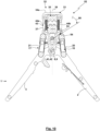
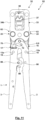
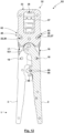
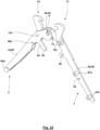
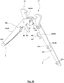
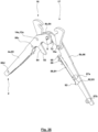
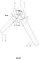
- Fig. 18 to 21 show the pliers 52 formed with the pliers head 32 and the pliers actuation assembly 1 in different assembly states: According to Fig. 18 The pliers head 32 is dismantled from the pliers actuation assembly 1. The pivot pin receptacle 41 of the pliers head 32 is freely accessible on the side facing the pliers actuation assembly 1. The pivot pin 8 and the pull tabs 16, 17 of the pliers actuation assembly 1 are also freely accessible on the side facing the pliers head 32, whereby the pull tabs 16, 17 can be freely pivoted in the pliers head plane.
- Fig. 19 the pliers actuation assembly 2 has been brought closer to the pliers head 32 in such a way that the pivot pin 8 enters the pivot pin receptacle 41 and comes to rest on the bottom of the pivot pin receptacle 41.
- the pull tabs 16, 17 are pivoted inwards, whereby the coupling pins 58, 59 of the pliers head 32 enter the coupling recesses 45, 46 of the pull tabs 16, 17.
- the length of the pull tabs 16, 17 is dimensioned such that this entry is only possible when the movable die half 37 moves in the closing direction while the spring device 43 is acted upon. With regard to the extent of the closing movement and the force ratios occurring here, what was said about the first embodiment applies accordingly.
- Fig. 22 shows the pull tabs 16, 17 as individual parts.
- the pull tabs 16, 17 are preferably formed in one piece with the base body 20, 21 and the pivot pins 14, 15 as well as the actuating element 57.
- the pull tabs 16, 17 are preferably manufactured in a MIN manufacturing process.
- Fig. 23 shows an alternative design of the pull tabs 16, 17, in which the base body 20, 21 and a pivot pin 61, which forms the pivot pins 14, 15, are designed separately from each other.
- the base body 20, 21 can be made, for example, as a milled or stamped part
- the base body 20, 21 then has a bore 62 in which the pivot pin 61 is precisely received, for example by means of a press fit.
- the pull tabs 16, 17 can also have a contact surface 53 which, when the pull tabs 16, 17 are pivoted in, comes into contact with a contact surface 54 of the movable die half 53.
- the contact surface can generate an actuating force component which causes a movement of the movable die half 37 in the closing direction in order to enable the coupling bolts 58, 59 to enter the coupling recesses 45, 46.
- the coupling recesses 45, 46 and the coupling elements 22, 23 form coupling devices 63, via which the pliers head 32 can be mounted to and dismounted from the pliers actuation assembly 1 (in particular without using a tool).
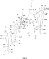
- Fig. 24 shows a pliers actuation assembly in a spatial exploded view, wherein the pliers actuation assembly 1 basically corresponds to the Fig. 14 to 23 described embodiment. However, the following also applies to a design corresponding to the embodiment in Fig. 1 to 13 .
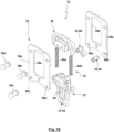
- the hand lever plate 4b of the hand lever 2 forms a first hand lever plate 64
- the hand lever plate 4a of the hand lever 2 forms a second hand lever plate 65
- the hand lever plate 5b of the hand lever 3 forms a third hand lever plate 66
- the hand lever plate 5a of the hand lever 3 forms a fourth hand lever plate 67.
- the first hand lever plate 64 has a recess 68 in the form of an elongated hole 69.
- An end region of the elongated hole 69 forms a stop 70.
- the elongated hole 69 has a circularly curved longitudinal axis which runs concentrically to the pivot axis of the two hand levers 2, 3 defined by the pivot pin 8.
- the third hand lever plate 66 has a holding and/or guide recess, which is designed here as a holding and/or guide hole 71.
- the distance of the holding and/or guide hole 71 from the pivot axis defined by the pivot pin 8 corresponds to the distance of the elongated hole 69 from the pivot axis defined by the pivot pin 8.
- Fig. 25 shows a stop part 72.
- the stop part 72 has or consists of a first cylindrical longitudinal section 73 with a first diameter and a second cylindrical longitudinal section 74 with a second diameter that is larger than the first diameter.
- the longitudinal sections 73, 74 are arranged coaxially to one another. The transition from the first longitudinal section 73 to the second longitudinal section 74 takes place via a shoulder 75, which here is formed by an annular surface 76.
- the first longitudinal section 73 is inserted from the inside, i.e.
- the holding and/or guide bore 71 which in particular provides radial guidance of the stop part 71 and specifies the position of the stop part 72 in the pivot plane of the hand levers 2, 3, as well as specifies the orientation of the stop part 72 vertically to this pivot plane.
- the stop part 72 is inserted into the holding and/or guide hole 71 so far that the shoulder 72 on the inner side of the third hand lever plate 66, i.e. on the side facing the hand lever plates 65, 67, comes to rest against the third hand lever plate 66, whereby the free end region of the first longitudinal section 73 protrudes from the third hand lever plate 66 and is arranged in the elongated hole 69.
- the front side of the first longitudinal section 73 is arranged flush with the outer surface of the first hand lever plate 64.
- the free end face of the second longitudinal section 74 forms a (here circular) support surface 77.
- the support surface 77 rests on the second hand lever plate 65.
- the stop part 72 is secured in the assembled state by the shoulder 75 resting on the third hand lever plate 66, while securing in the opposite direction is achieved by the support surface 77 resting on the second hand lever plate 65, so that the stop part 72 is caught between the second hand lever plate 65 and the third hand lever plate 66.
- Fig. 26 shows the pivot pin 8 in a spatial representation. It can be seen here that the pivot pin 8 has a first cylindrical longitudinal section 78 and a second cylindrical longitudinal section 79, which are separated from one another by a shoulder 80, which is designed as a circular ring surface 81.
- the pivot pin 8 with the first longitudinal section 78 is inserted into the bearing eye 6b until the circular ring surface 81 on the inside comes to rest against the first hand lever plate 64. Subsequently, the second, third and fourth hand lever plates 65, 66, 67 are pushed onto the pivot pin 8 with the bearing eyes 7b, 6a, 7a.
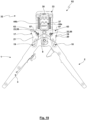
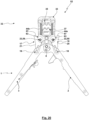
- the pliers actuation assembly 1 has a positive locking mechanism 82.
- a positive locking mechanism 82 serves to ensure that a partial closed position of the hand levers 2, 3 is secured in several partial stages during the pressing or crimping stroke, so that even if the manual forces applied to the hand levers 2, 3 are reduced, no opening movement of the hand levers 2, 3 is possible. Rather, the positive locking mechanism 82 only enables an opening movement of the hand levers 2, 3 when the pressing or crimping stroke has been completed completely or up to a defined closed position.
- the positive locking mechanism 82 has a toothing 83, which is formed here by an extension 84 of the second hand lever plate 65.
- the positive locking mechanism 82 also has a pawl 85.
- the pawl 85 is pivotally mounted and acted upon by a spring 86.
- the pawl 85 interacts with the toothing 83 in such a way that the pawl 85 has passed a tooth of the toothing 83 in a ratchet-like manner during the closing movement of the hand levers 2, 3 when a partially closed position to be secured is reached, while the pawl 85 blocks an opening movement by suitable support on the tooth it has passed.
- the locking pawl 85 can fold over, whereby the locking pawl 85 can then pass the toothing 83 of the hand levers 2, 3 in a ratchet-like manner during an opening movement that is then possible.
- the assembly begins with the provision of the first hand lever plate 64 (see Fig. 27 ).
- the first longitudinal section 78 of the pivot pin 8 is then inserted into the bearing eye 6b of the first hand lever plate 64 from the inside of the first hand lever plate 64 until the shoulder 80 of the pivot pin 8 comes to rest against the hand lever plate 64 (cf. Fig. 28 ).
- Fig. 29 shows the end position of the third hand lever plate 66, in which the first and third hand lever plates 64, 66 slide against each other under the guidance of the pivot pin 8.
- the first longitudinal section 73 of the stop part 72 is inserted from the inside into the holding and/or guide bore 71 and guided through it until the free end region of the first longitudinal section 73 is received in the elongated hole 69 (cf. Fig. 30 ).
- spacers 87a, 87b, 87c, 87d are then inserted into receptacles 88a, 88b, 88c, 88d.
- the spacers 87 each have a central cylindrical longitudinal section, the longitudinal extent of which determines the distance between the second hand lever plate 65 and the third hand lever plate 66, and cylindrical end-side longitudinal sections that form pins that are received in the receptacles 88 in the hand lever plates 64, 66 (and later also the hand lever plates 65, 67), which are designed as bores.
- the pins have a smaller diameter than the central longitudinal section, so that the transition from the central longitudinal section to the pins takes place via a shoulder, here in the form of a circular ring surface. These shoulders are then caught between the second and third hand lever plates 65, 66, whereby the spacers 87 between the hand lever plates 65, 66 are secured against disassembly in a direction vertical to the pivot plane of the hand levers 2, 3. The spacers 87 then specify the gap between the pairs of hand lever plates 64, 66 and 65, 67 which can be pivoted relative to one another.
- the second hand lever plate 65 is then joined. During this joining, the bearing eye 6a of the second hand lever plate 65 is placed on the Swivel pin 8 is pushed on. At the same time, the swivel pin 14a enters the hole 12a of the second hand lever plate 65 and the pins of the spacers 87a, 87b enter the receptacles 88c, 88d of the second hand lever plate 65.
- the assembly state then achieved is shown in Fig. 33 shown.
- the locking pawl 85 is mounted to the third hand lever plate 66 by fitting an extension 89 of the locking pawl 85 into a receptacle 90 of the third hand lever plate 66 (cf. Fig. 34 ).
- the spring 86 is then assembled.
- the spring 86 is designed as a leaf spring 91.
- a spring base of the leaf spring 91 has an extension 92, which is received in a receptacle 93 of the third hand lever plate 66.
- the leaf spring 91 is supported adjacent to the extension 92 on a spacer 87 in the bending direction of the leaf spring 91.
- the leaf spring 91 projects freely and is supported in the end region facing away from the extension 92 on the pawl 85, under pressure from the pawl (see. Fig. 35 ).
- the hand lever plates 64, 65, 66, 67 are then fixed. This is done, for example, by connecting, in particular pressing, screwing, riveting or similar, the spacers 87 in the receptacles of the hand lever plates 64, 65, 66, 67.
- the pivot pin 8 can also be pressed, but this must be done while maintaining the pivoting degree of freedom of the hand levers 2, 3.
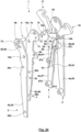
- Fig. 38 shows an alternative embodiment of a pliers actuation assembly 1.
- the cylindrical section of the stop part 72 arranged in front of the shoulder 75 extends only in a holding and/or guide bore 71 of the third hand lever plate 66, on which the shoulder 75 is supported outwards.
- the cylindrical section of the stop part 72 with the larger diameter is in this case received and guided in the elongated hole 69.
- the front support surface 77 of the stop part 72 is slidably guided on the fourth hand lever plate 67.
- the stop part 72 is thus caught between the contact of the shoulder 75 on the third hand lever plate 66 and the contact of the support surface 77 on the fourth hand lever plate 67 and is secured in this way.
- a pivotable mounting of a spring 86 of the positive locking mechanism, a pawl 85 of the positive locking mechanism and/or pull tabs 16, 17 in recesses or bores of hand lever plates 64, 65 or 66, 67 of a hand lever 2, 3 can also be carried out, wherein the spring 86, the pawl 85 and/or the pull tabs 16, 17 are then caught between the two hand lever plates 64, 65 or 66, 67, as is the subject of the European patent application filed on the same day EP22 207 540.0 of the applicant, which in this respect is made the subject of the present patent application.
Landscapes
- Engineering & Computer Science (AREA)
- Mechanical Engineering (AREA)
- Manufacturing & Machinery (AREA)
- Manufacturing Of Electrical Connectors (AREA)
- Gripping Jigs, Holding Jigs, And Positioning Jigs (AREA)
- Hand Tools For Fitting Together And Separating, Or Other Hand Tools (AREA)
- Scissors And Nippers (AREA)
- Surgical Instruments (AREA)
Priority Applications (5)
| Application Number | Priority Date | Filing Date | Title |
|---|---|---|---|
| EP22207566.5A EP4371707B1 (fr) | 2022-11-15 | 2022-11-15 | Ensemble d'actionnement de pince, pince et procédé d'assemblage |
| JP2023192868A JP2024072271A (ja) | 2022-11-15 | 2023-11-13 | プライヤ作動アセンブリグループ、プライヤ及び組立方法 |
| TW112143579A TW202432308A (zh) | 2022-11-15 | 2023-11-13 | 鉗子致動組件組、鉗子以及用於組裝的方法 |
| US18/389,266 US20240157530A1 (en) | 2022-11-15 | 2023-11-14 | Pliers actuation assembly group, pliers and method for assembling |
| CN202311519185.2A CN118046330A (zh) | 2022-11-15 | 2023-11-15 | 钳子致动组件组、钳子以及用于组装的方法 |
Applications Claiming Priority (1)
| Application Number | Priority Date | Filing Date | Title |
|---|---|---|---|
| EP22207566.5A EP4371707B1 (fr) | 2022-11-15 | 2022-11-15 | Ensemble d'actionnement de pince, pince et procédé d'assemblage |
Publications (3)
| Publication Number | Publication Date |
|---|---|
| EP4371707A1 true EP4371707A1 (fr) | 2024-05-22 |
| EP4371707C0 EP4371707C0 (fr) | 2025-03-05 |
| EP4371707B1 EP4371707B1 (fr) | 2025-03-05 |
Family
ID=84358177
Family Applications (1)
| Application Number | Title | Priority Date | Filing Date |
|---|---|---|---|
| EP22207566.5A Active EP4371707B1 (fr) | 2022-11-15 | 2022-11-15 | Ensemble d'actionnement de pince, pince et procédé d'assemblage |
Country Status (5)
| Country | Link |
|---|---|
| US (1) | US20240157530A1 (fr) |
| EP (1) | EP4371707B1 (fr) |
| JP (1) | JP2024072271A (fr) |
| CN (1) | CN118046330A (fr) |
| TW (1) | TW202432308A (fr) |
Citations (15)
| Publication number | Priority date | Publication date | Assignee | Title |
|---|---|---|---|---|
| DE3708727C2 (fr) | 1986-04-09 | 1988-07-28 | Wezag Gmbh Werkzeugfabrik, 3570 Stadtallendorf, De | |
| DE19709639A1 (de) | 1997-03-08 | 1998-09-10 | Wezag Gmbh | Zange zum Verpressen von Fassungen, Rohren, Kabelschuhen u. dgl. |
| DE19802287C1 (de) | 1998-01-22 | 1998-12-24 | Wezag Gmbh | Preßzange mit auswechselbaren Preßbacken |
| DE19713580C2 (de) | 1997-04-02 | 1999-12-30 | Wezag Gmbh | Preßzange zum Verformen eines Werkstückes |
| DE19807737C2 (de) | 1998-02-24 | 2000-06-21 | Wezag Gmbh | Zange zum Verpressen von Werkstücken |
| DE19834859C2 (de) | 1998-08-01 | 2001-01-11 | Wezag Gmbh | Zange zum Verpressen von Werkstücken |
| DE19963097C1 (de) | 1999-12-24 | 2001-04-12 | Wezag Gmbh | Zange zum Verpressen eines Werkstücks |
| DE19924087C2 (de) | 1999-05-26 | 2002-06-20 | Wezag Gmbh | Zange zum Verpressen von Fassungen, Rohren, Kabelschuhen und dgl. |
| DE10056900C1 (de) | 2000-11-16 | 2002-08-08 | Wezag Gmbh | Handbetätigbare Zange zum Crimpen, Schneiden, Pressen o. dgl. |
| DE19924086C2 (de) | 1999-05-26 | 2002-08-08 | Wezag Gmbh | Zange zum Verpressen von Fassungen, Rohren, Kabelschuhen und dgl. |
| DE19753436C2 (de) | 1997-12-02 | 2002-10-24 | Wezag Gmbh | Preßwerkzeug zum Verpressen eines gedrehten Rundsteckers und eines mehrdrähtigen Leiters |
| DE10346241B3 (de) | 2003-10-06 | 2004-08-12 | Wezag Gmbh Werkzeugfabrik | Zange zum Verpressen von Werkstücken |
| EP2305428A1 (fr) | 2009-09-30 | 2011-04-06 | Wezag GmbH Werkzeugfabrik | Pince |
| EP2995424A1 (fr) | 2014-09-11 | 2016-03-16 | Wezag GmbH Werkzeugfabrik | Pince |
| EP3208044A1 (fr) | 2016-02-18 | 2017-08-23 | Wezag GmbH Werkzeugfabrik | Pince comprenant un systeme de levier a genouillere |
Family Cites Families (4)
| Publication number | Priority date | Publication date | Assignee | Title |
|---|---|---|---|---|
| DE4023337C1 (fr) * | 1990-07-23 | 1991-10-24 | Wezag Gmbh Werkzeugfabrik, 3570 Stadtallendorf, De | |
| DE20203207U1 (de) * | 2002-02-28 | 2002-05-16 | Chen, Jin-Fu, Ta Li, Taichung | Werkzeug |
| TWM362080U (en) * | 2009-03-11 | 2009-08-01 | Hanlong Ind Co Ltd | Labor-saving tool |
| US8555754B2 (en) * | 2010-12-06 | 2013-10-15 | Js Products, Inc. | Biased pliers |
-
2022
- 2022-11-15 EP EP22207566.5A patent/EP4371707B1/fr active Active
-
2023
- 2023-11-13 JP JP2023192868A patent/JP2024072271A/ja active Pending
- 2023-11-13 TW TW112143579A patent/TW202432308A/zh unknown
- 2023-11-14 US US18/389,266 patent/US20240157530A1/en active Pending
- 2023-11-15 CN CN202311519185.2A patent/CN118046330A/zh active Pending
Patent Citations (15)
| Publication number | Priority date | Publication date | Assignee | Title |
|---|---|---|---|---|
| DE3708727C2 (fr) | 1986-04-09 | 1988-07-28 | Wezag Gmbh Werkzeugfabrik, 3570 Stadtallendorf, De | |
| DE19709639A1 (de) | 1997-03-08 | 1998-09-10 | Wezag Gmbh | Zange zum Verpressen von Fassungen, Rohren, Kabelschuhen u. dgl. |
| DE19713580C2 (de) | 1997-04-02 | 1999-12-30 | Wezag Gmbh | Preßzange zum Verformen eines Werkstückes |
| DE19753436C2 (de) | 1997-12-02 | 2002-10-24 | Wezag Gmbh | Preßwerkzeug zum Verpressen eines gedrehten Rundsteckers und eines mehrdrähtigen Leiters |
| DE19802287C1 (de) | 1998-01-22 | 1998-12-24 | Wezag Gmbh | Preßzange mit auswechselbaren Preßbacken |
| DE19807737C2 (de) | 1998-02-24 | 2000-06-21 | Wezag Gmbh | Zange zum Verpressen von Werkstücken |
| DE19834859C2 (de) | 1998-08-01 | 2001-01-11 | Wezag Gmbh | Zange zum Verpressen von Werkstücken |
| DE19924086C2 (de) | 1999-05-26 | 2002-08-08 | Wezag Gmbh | Zange zum Verpressen von Fassungen, Rohren, Kabelschuhen und dgl. |
| DE19924087C2 (de) | 1999-05-26 | 2002-06-20 | Wezag Gmbh | Zange zum Verpressen von Fassungen, Rohren, Kabelschuhen und dgl. |
| DE19963097C1 (de) | 1999-12-24 | 2001-04-12 | Wezag Gmbh | Zange zum Verpressen eines Werkstücks |
| DE10056900C1 (de) | 2000-11-16 | 2002-08-08 | Wezag Gmbh | Handbetätigbare Zange zum Crimpen, Schneiden, Pressen o. dgl. |
| DE10346241B3 (de) | 2003-10-06 | 2004-08-12 | Wezag Gmbh Werkzeugfabrik | Zange zum Verpressen von Werkstücken |
| EP2305428A1 (fr) | 2009-09-30 | 2011-04-06 | Wezag GmbH Werkzeugfabrik | Pince |
| EP2995424A1 (fr) | 2014-09-11 | 2016-03-16 | Wezag GmbH Werkzeugfabrik | Pince |
| EP3208044A1 (fr) | 2016-02-18 | 2017-08-23 | Wezag GmbH Werkzeugfabrik | Pince comprenant un systeme de levier a genouillere |
Also Published As
| Publication number | Publication date |
|---|---|
| EP4371707C0 (fr) | 2025-03-05 |
| CN118046330A (zh) | 2024-05-17 |
| TW202432308A (zh) | 2024-08-16 |
| JP2024072271A (ja) | 2024-05-27 |
| EP4371707B1 (fr) | 2025-03-05 |
| US20240157530A1 (en) | 2024-05-16 |
Similar Documents
| Publication | Publication Date | Title |
|---|---|---|
| EP3904007B1 (fr) | Matrice de pince à sertir et pince à sertir | |
| EP3012923B1 (fr) | Pince de pression | |
| DE10056900C1 (de) | Handbetätigbare Zange zum Crimpen, Schneiden, Pressen o. dgl. | |
| EP2562891B1 (fr) | Pince de pression | |
| EP2463969B1 (fr) | Tête de pince pour une pince de sertissage | |
| DE102008012011B3 (de) | Zangenkopf | |
| EP3984702B1 (fr) | Pince à serrer et procédé de montage d'une unité de moitiés de matrice | |
| EP3553899B1 (fr) | Outil de sertissage | |
| EP3553900B1 (fr) | Mâchoire pivotante de pince du type à plaques et pince de sertissage pourvue de mâchoire pivotante de pince | |
| EP3834989B1 (fr) | Outil pince à main et procédé de montage d'un tel outil | |
| EP3904006B1 (fr) | Matrice de pince à sertir et pince à sertir | |
| EP2873122A1 (fr) | Outil de sertissage d'embouts | |
| EP3614507A1 (fr) | Pinces à presser ou à sertir | |
| EP0468335A2 (fr) | Outil pour le sertissage d'un connecteur à un conducteur et une isolation | |
| EP3300187B1 (fr) | Positionneur d'outil de presse et outil de presse | |
| DE102008013044B3 (de) | Adapter für ein Blindniet-Setzgerät und Blindniet-Setzgerät | |
| EP1922787B1 (fr) | Outil de double sertissage | |
| DE202018105955U1 (de) | Crimpkopf und Crimpwerkzeug | |
| DE9307957U1 (de) | Montagewerkzeug für Schiebehülsen-Rohrverbindungen | |
| EP3100827B1 (fr) | Système de levier de presse doté d'un levier de presse et d'une mâchoire de presse | |
| EP4371707B1 (fr) | Ensemble d'actionnement de pince, pince et procédé d'assemblage | |
| EP4371705B1 (fr) | Procédé d'assemblage d'un ensemble d'actionnement de pince, ensemble d'actionnement de pince et pince | |
| EP4371706B1 (fr) | Pince de sertissage, tête de pince de sertissage, module d'actionnement de pince de sertissage et procédé de montage d'une pince de sertissage | |
| EP1157758B1 (fr) | Dispositif pour débosseler des tôles | |
| EP4636208A2 (fr) | Ferrure pour le montage mobile d'un élément pivotant |
Legal Events
| Date | Code | Title | Description |
|---|---|---|---|
| PUAI | Public reference made under article 153(3) epc to a published international application that has entered the european phase |
Free format text: ORIGINAL CODE: 0009012 |
|
| STAA | Information on the status of an ep patent application or granted ep patent |
Free format text: STATUS: REQUEST FOR EXAMINATION WAS MADE |
|
| 17P | Request for examination filed |
Effective date: 20230601 |
|
| AK | Designated contracting states |
Kind code of ref document: A1 Designated state(s): AL AT BE BG CH CY CZ DE DK EE ES FI FR GB GR HR HU IE IS IT LI LT LU LV MC ME MK MT NL NO PL PT RO RS SE SI SK SM TR |
|
| RIC1 | Information provided on ipc code assigned before grant |
Ipc: H01R 43/042 20060101ALI20240715BHEP Ipc: B25B 27/14 20060101ALI20240715BHEP Ipc: B25B 7/16 20060101AFI20240715BHEP |
|
| GRAP | Despatch of communication of intention to grant a patent |
Free format text: ORIGINAL CODE: EPIDOSNIGR1 |
|
| STAA | Information on the status of an ep patent application or granted ep patent |
Free format text: STATUS: GRANT OF PATENT IS INTENDED |
|
| INTG | Intention to grant announced |
Effective date: 20240905 |
|
| GRAS | Grant fee paid |
Free format text: ORIGINAL CODE: EPIDOSNIGR3 |
|
| GRAA | (expected) grant |
Free format text: ORIGINAL CODE: 0009210 |
|
| STAA | Information on the status of an ep patent application or granted ep patent |
Free format text: STATUS: THE PATENT HAS BEEN GRANTED |
|
| AK | Designated contracting states |
Kind code of ref document: B1 Designated state(s): AL AT BE BG CH CY CZ DE DK EE ES FI FR GB GR HR HU IE IS IT LI LT LU LV MC ME MK MT NL NO PL PT RO RS SE SI SK SM TR |
|
| REG | Reference to a national code |
Ref country code: GB Ref legal event code: FG4D Free format text: NOT ENGLISH |
|
| REG | Reference to a national code |
Ref country code: CH Ref legal event code: EP |
|
| REG | Reference to a national code |
Ref country code: IE Ref legal event code: FG4D Free format text: LANGUAGE OF EP DOCUMENT: GERMAN |
|
| REG | Reference to a national code |
Ref country code: DE Ref legal event code: R096 Ref document number: 502022003089 Country of ref document: DE |
|
| U01 | Request for unitary effect filed |
Effective date: 20250319 |
|
| U07 | Unitary effect registered |
Designated state(s): AT BE BG DE DK EE FI FR IT LT LU LV MT NL PT RO SE SI Effective date: 20250325 |
|
| PG25 | Lapsed in a contracting state [announced via postgrant information from national office to epo] |
Ref country code: RS Free format text: LAPSE BECAUSE OF FAILURE TO SUBMIT A TRANSLATION OF THE DESCRIPTION OR TO PAY THE FEE WITHIN THE PRESCRIBED TIME-LIMIT Effective date: 20250605 |
|
| PG25 | Lapsed in a contracting state [announced via postgrant information from national office to epo] |
Ref country code: ES Free format text: LAPSE BECAUSE OF FAILURE TO SUBMIT A TRANSLATION OF THE DESCRIPTION OR TO PAY THE FEE WITHIN THE PRESCRIBED TIME-LIMIT Effective date: 20250305 |
|
| PG25 | Lapsed in a contracting state [announced via postgrant information from national office to epo] |
Ref country code: NO Free format text: LAPSE BECAUSE OF FAILURE TO SUBMIT A TRANSLATION OF THE DESCRIPTION OR TO PAY THE FEE WITHIN THE PRESCRIBED TIME-LIMIT Effective date: 20250605 |
|
| PG25 | Lapsed in a contracting state [announced via postgrant information from national office to epo] |
Ref country code: HR Free format text: LAPSE BECAUSE OF FAILURE TO SUBMIT A TRANSLATION OF THE DESCRIPTION OR TO PAY THE FEE WITHIN THE PRESCRIBED TIME-LIMIT Effective date: 20250305 |
|
| PG25 | Lapsed in a contracting state [announced via postgrant information from national office to epo] |
Ref country code: GR Free format text: LAPSE BECAUSE OF FAILURE TO SUBMIT A TRANSLATION OF THE DESCRIPTION OR TO PAY THE FEE WITHIN THE PRESCRIBED TIME-LIMIT Effective date: 20250606 |
|
| PG25 | Lapsed in a contracting state [announced via postgrant information from national office to epo] |
Ref country code: SM Free format text: LAPSE BECAUSE OF FAILURE TO SUBMIT A TRANSLATION OF THE DESCRIPTION OR TO PAY THE FEE WITHIN THE PRESCRIBED TIME-LIMIT Effective date: 20250305 |
|
| PG25 | Lapsed in a contracting state [announced via postgrant information from national office to epo] |
Ref country code: PL Free format text: LAPSE BECAUSE OF FAILURE TO SUBMIT A TRANSLATION OF THE DESCRIPTION OR TO PAY THE FEE WITHIN THE PRESCRIBED TIME-LIMIT Effective date: 20250305 |
|
| PG25 | Lapsed in a contracting state [announced via postgrant information from national office to epo] |
Ref country code: CZ Free format text: LAPSE BECAUSE OF FAILURE TO SUBMIT A TRANSLATION OF THE DESCRIPTION OR TO PAY THE FEE WITHIN THE PRESCRIBED TIME-LIMIT Effective date: 20250305 |
|
| PG25 | Lapsed in a contracting state [announced via postgrant information from national office to epo] |
Ref country code: SK Free format text: LAPSE BECAUSE OF FAILURE TO SUBMIT A TRANSLATION OF THE DESCRIPTION OR TO PAY THE FEE WITHIN THE PRESCRIBED TIME-LIMIT Effective date: 20250305 |
|
| PG25 | Lapsed in a contracting state [announced via postgrant information from national office to epo] |
Ref country code: IS Free format text: LAPSE BECAUSE OF FAILURE TO SUBMIT A TRANSLATION OF THE DESCRIPTION OR TO PAY THE FEE WITHIN THE PRESCRIBED TIME-LIMIT Effective date: 20250705 |
|
| U20 | Renewal fee for the european patent with unitary effect paid |
Year of fee payment: 4 Effective date: 20251009 |
|
| PLBE | No opposition filed within time limit |
Free format text: ORIGINAL CODE: 0009261 |
|
| STAA | Information on the status of an ep patent application or granted ep patent |
Free format text: STATUS: NO OPPOSITION FILED WITHIN TIME LIMIT |
|
| REG | Reference to a national code |
Ref country code: CH Ref legal event code: L10 Free format text: ST27 STATUS EVENT CODE: U-0-0-L10-L00 (AS PROVIDED BY THE NATIONAL OFFICE) Effective date: 20260114 |
|
| 26N | No opposition filed |
Effective date: 20251208 |