EP4375165A2 - Systèmes de direction pour chariots élévateurs - Google Patents
Systèmes de direction pour chariots élévateurs Download PDFInfo
- Publication number
- EP4375165A2 EP4375165A2 EP24169392.8A EP24169392A EP4375165A2 EP 4375165 A2 EP4375165 A2 EP 4375165A2 EP 24169392 A EP24169392 A EP 24169392A EP 4375165 A2 EP4375165 A2 EP 4375165A2
- Authority
- EP
- European Patent Office
- Prior art keywords
- wheel
- wheel assembly
- mode
- sideward
- truck
- Prior art date
- Legal status (The legal status is an assumption and is not a legal conclusion. Google has not performed a legal analysis and makes no representation as to the accuracy of the status listed.)
- Granted
Links
Images







Classifications
-
- B—PERFORMING OPERATIONS; TRANSPORTING
- B62—LAND VEHICLES FOR TRAVELLING OTHERWISE THAN ON RAILS
- B62D—MOTOR VEHICLES; TRAILERS
- B62D7/00—Steering linkage; Stub axles or their mountings
- B62D7/06—Steering linkage; Stub axles or their mountings for individually-pivoted wheels, e.g. on king-pins
- B62D7/14—Steering linkage; Stub axles or their mountings for individually-pivoted wheels, e.g. on king-pins the pivotal axes being situated in more than one plane transverse to the longitudinal centre line of the vehicle, e.g. all-wheel steering
- B62D7/15—Steering linkage; Stub axles or their mountings for individually-pivoted wheels, e.g. on king-pins the pivotal axes being situated in more than one plane transverse to the longitudinal centre line of the vehicle, e.g. all-wheel steering characterised by means varying the ratio between the steering angles of the steered wheels
- B62D7/1509—Steering linkage; Stub axles or their mountings for individually-pivoted wheels, e.g. on king-pins the pivotal axes being situated in more than one plane transverse to the longitudinal centre line of the vehicle, e.g. all-wheel steering characterised by means varying the ratio between the steering angles of the steered wheels with different steering modes, e.g. crab-steering, or steering specially adapted for reversing of the vehicle
-
- B—PERFORMING OPERATIONS; TRANSPORTING
- B62—LAND VEHICLES FOR TRAVELLING OTHERWISE THAN ON RAILS
- B62D—MOTOR VEHICLES; TRAILERS
- B62D7/00—Steering linkage; Stub axles or their mountings
- B62D7/06—Steering linkage; Stub axles or their mountings for individually-pivoted wheels, e.g. on king-pins
- B62D7/14—Steering linkage; Stub axles or their mountings for individually-pivoted wheels, e.g. on king-pins the pivotal axes being situated in more than one plane transverse to the longitudinal centre line of the vehicle, e.g. all-wheel steering
- B62D7/142—Steering linkage; Stub axles or their mountings for individually-pivoted wheels, e.g. on king-pins the pivotal axes being situated in more than one plane transverse to the longitudinal centre line of the vehicle, e.g. all-wheel steering specially adapted for particular vehicles, e.g. tractors, carts, earth-moving vehicles, trucks
-
- B—PERFORMING OPERATIONS; TRANSPORTING
- B66—HOISTING; LIFTING; HAULING
- B66F—HOISTING, LIFTING, HAULING OR PUSHING, NOT OTHERWISE PROVIDED FOR, e.g. DEVICES WHICH APPLY A LIFTING OR PUSHING FORCE DIRECTLY TO THE SURFACE OF A LOAD
- B66F9/00—Devices for lifting or lowering bulky or heavy goods for loading or unloading purposes
- B66F9/06—Devices for lifting or lowering bulky or heavy goods for loading or unloading purposes movable, with their loads, on wheels or the like, e.g. fork-lift trucks
- B66F9/075—Constructional features or details
- B66F9/07509—Braking
-
- B—PERFORMING OPERATIONS; TRANSPORTING
- B66—HOISTING; LIFTING; HAULING
- B66F—HOISTING, LIFTING, HAULING OR PUSHING, NOT OTHERWISE PROVIDED FOR, e.g. DEVICES WHICH APPLY A LIFTING OR PUSHING FORCE DIRECTLY TO THE SURFACE OF A LOAD
- B66F9/00—Devices for lifting or lowering bulky or heavy goods for loading or unloading purposes
- B66F9/06—Devices for lifting or lowering bulky or heavy goods for loading or unloading purposes movable, with their loads, on wheels or the like, e.g. fork-lift trucks
- B66F9/075—Constructional features or details
- B66F9/07568—Steering arrangements
-
- B—PERFORMING OPERATIONS; TRANSPORTING
- B66—HOISTING; LIFTING; HAULING
- B66F—HOISTING, LIFTING, HAULING OR PUSHING, NOT OTHERWISE PROVIDED FOR, e.g. DEVICES WHICH APPLY A LIFTING OR PUSHING FORCE DIRECTLY TO THE SURFACE OF A LOAD
- B66F9/00—Devices for lifting or lowering bulky or heavy goods for loading or unloading purposes
- B66F9/06—Devices for lifting or lowering bulky or heavy goods for loading or unloading purposes movable, with their loads, on wheels or the like, e.g. fork-lift trucks
- B66F9/075—Constructional features or details
- B66F9/07572—Propulsion arrangements
-
- B—PERFORMING OPERATIONS; TRANSPORTING
- B66—HOISTING; LIFTING; HAULING
- B66F—HOISTING, LIFTING, HAULING OR PUSHING, NOT OTHERWISE PROVIDED FOR, e.g. DEVICES WHICH APPLY A LIFTING OR PUSHING FORCE DIRECTLY TO THE SURFACE OF A LOAD
- B66F9/00—Devices for lifting or lowering bulky or heavy goods for loading or unloading purposes
- B66F9/06—Devices for lifting or lowering bulky or heavy goods for loading or unloading purposes movable, with their loads, on wheels or the like, e.g. fork-lift trucks
- B66F9/075—Constructional features or details
- B66F9/20—Means for actuating or controlling masts, platforms, or forks
- B66F9/22—Hydraulic devices or systems
-
- B—PERFORMING OPERATIONS; TRANSPORTING
- B62—LAND VEHICLES FOR TRAVELLING OTHERWISE THAN ON RAILS
- B62D—MOTOR VEHICLES; TRAILERS
- B62D9/00—Steering deflectable wheels not otherwise provided for
- B62D9/002—Steering deflectable wheels not otherwise provided for combined with means for differentially distributing power on the deflectable wheels during cornering
Definitions
- This invention relates to steering systems for lift trucks, and in particular to lift trucks which can be steered in forward and sideward modes.
- WO 03/059799 describes a lift truck having forward and sideward modes of operation.
- the document describes and shows a three-wheel truck with two front wheels and one rear wheel, all of the wheels being driven and steerable.
- the two front wheels are fixed in a straight-ahead angular position parallel to the forks and the main longitudinal axis of the chassis, and the steering mechanism is coupled to the rear wheel to steer the truck.
- the three wheels are turned to be perpendicular to the longitudinal axis, and the rear wheel's steering angle is fixed in that position, while the steering mechanism is coupled to the front wheels which steer in synchronicity to direct the truck.
- the wheels in this truck are steered in position from above, i.e. a bogey with the wheel is mounted to the chassis on a pivot that is vertically located above the centre of the wheel, and a steering motor rotates the bogey, so that the wheels can be turned through 90 degrees in position on the ground.
- the brakes are applied to the wheels so that if the truck is, for example, disposed on a slope with its longitudinal axis perpendicular to the slope, it will not start to roll sideways as the wheels are turned sideways.
- a steering system for a lift truck having a chassis with a longitudinal axis, the steering system comprising:
- the steering actuator no longer needs to be above the assembly or bogey. This then enables the height of the mechanism to be reduced. Laterally offsetting the wheels, however, prevents them from changing their angular orientation while remaining in the same fixed position: they must travel over the ground.
- the driving of the wheel assists the pivotal rotation caused by the actuator. This reduces the stress on the pivoting mechanism and decreases the chance that the truck will unintentionally roll or shift position during the mode change manoeuvre.
- the positive drive imparted by the drive means to the wheel will help to prevent the truck from rolling down the slope.
- the steering actuator is aided by the powered wheel drive, this reduces the forces within the system when changing modes and allows for smaller and more compact actuators, while also reducing wear and tear, and the likelihood of failure of the actuator if resistance is met while transitioning the wheel.
- the drive means is controlled to drive the wheel along said arcuate path at a speed that matches the pivotal rotation caused by the actuator.
- the speed matching need not be exact: it is sufficient that the wheel is imparted with positive drive at a speed that avoids wheel scrubbing and that counteracts any rolling tendency if the manoeuvre is made on sloping ground given the weight of the vehicle and the range of slopes on which it is designed to operate. Preferably, however, the speed matching is done accurately.
- the controller may be preferably designed to drive the wheel at a speed over the ground that matches the speed imparted to that wheel over the ground by the pivoting mechanism to within say 10% or 5%.
- the drive means is controlled to drive the wheel by a distance that matches the length of said arcuate path.
- the transition between forward and sideward modes may be from forward to sideward mode or from sideward to forward mode.
- the controller is preferably configured or programmed with a sequence of operations to perform the actuation of the actuator and drive means of the pair of wheel assemblies in a controlled and co-ordinated manner to perform the transition.
- the rotation of the pair of wheel assemblies about their respective pivot points can be controlled to occur simultaneously, or in a controlled sequence, or independently of one another.
- the controller is further operable to control a braking system of the forklift truck, such that a brake for each of said wheels may be independently applied or released.
- the controller is configured to cause a brake to be applied to each of said wheels while it is not being moved by the pivotal rotation of the associated wheel assembly about its pivot point.
- controller is configured to cause the brake to be released for each wheel while the associated wheel assembly is being pivotally rotated.
- the controller applies the brake on each of said wheels before beginning the transition and on completing the transition.
- this wheel is also braked while the wheel assemblies are being pivotally rotated.
- the truck will typically be a three-wheel or four-wheel truck (though more wheels could be present as the skilled person will readily appreciate).
- the drive means to each of the pair of wheels is an independent electric drive motor.
- the actuator for each wheel assembly is a hydraulic actuator.
- the respective hydraulic actuators to the pair of wheel assemblies are ganged, with one actuator being a master and the other being a slave, such that the displacement of the two hydraulic actuators is the same and the steering angle of each wheel is equal in magnitude.
- the angular positions of the wheels are changed in equal and opposite directions during the transition.
- a third wheel will typically be mounted on the chassis spaced apart from the wheel assemblies in the longitudinal direction.
- the third wheel is disposed on the longitudinal axis of the chassis.
- the third wheel is steerable through at least 90 degrees between a forward mode wherein a third wheel axle is directed transversely towards the longitudinal axis and a sideward mode wherein the third wheel axle is parallel to the longitudinal axis.
- the third wheel is controlled to transition between the forward mode and the sideward mode in concert with the pair of wheel assemblies.
- the controller is operable to cause said transition of the third wheel between the forward mode and the sideward mode in concert with the pair of wheel assemblies as part of a programmed sequence of operations.
- the third wheel is pivotally mounted on the chassis to rotate in place without translation as it transitions between forward and sideward modes. This may be done, for example, by having the pivotal mounting directly above the point of contact between the third wheel and the ground (when the truck is in normal orientation on level ground).
- the controller is further adapted to cause the third wheel to be braked throughout the transition.
- the braking of a wheel can be mechanical or can be achieved by electric braking of an electric motor, or hydraulic braking of a hydraulic motor, for example.
- the third wheel is mounted on a third wheel assembly in the same manner as said pair of wheel assemblies, the third wheel assembly being pivotally mounted on the chassis and the third wheel being offset from the pivotal mounting point of the third wheel assembly.
- the brake on the third wheel is preferably released during the pivotal rotation of the third wheel assembly and applied at other times during the transition.
- the steering system further comprises a third actuator acting on the third wheel assembly to control the angular orientation of the third wheel assembly about the pivot point, a drive means is provided operating on the third wheel to drive the third wheel over the ground, and said controller is operable to simultaneously actuate the third actuator to cause the third wheel assembly to pivotally rotate about its pivot point, and actuate the third wheel drive means to impart positive drive to the third wheel and drive the third wheel along an arcuate path at a speed that matches the pivotal rotation caused by the third actuator.
- a third actuator acting on the third wheel assembly to control the angular orientation of the third wheel assembly about the pivot point
- a drive means is provided operating on the third wheel to drive the third wheel over the ground
- said controller is operable to simultaneously actuate the third actuator to cause the third wheel assembly to pivotally rotate about its pivot point, and actuate the third wheel drive means to impart positive drive to the third wheel and drive the third wheel along an arcuate path at a speed that matches the pivotal rotation caused by the third actuator.
- a fourth wheel is preferably disposed, spaced apart from the third wheel on opposite sides of the longitudinal axis, and the third and fourth wheels are spaced apart from the pair of wheel assemblies in the longitudinal direction.
- a steering system for a lift truck the lift truck having a chassis with a longitudinal axis, the steering system comprising:
- the wheel that is unbraked and that is pivotally being rotated is in a freewheel state, which simplifies the mode change operation by removing the need to apply positive drive to a wheel during its transition.
- the pivotal rotation of a wheel assembly may optionally also be assisted by driving the wheel of the pivoting wheel assembly across the ground as previously described.
- said controller may simultaneously actuate the actuator of a wheel assembly to cause said wheel assembly to pivotally rotate about its pivot point, and actuate the drive means operating on the wheel of said wheel assembly to impart positive drive to said wheel and drive said wheel along said arcuate path to assist the pivotal rotation caused by the actuator.
- the drive means is controlled to drive the wheel along said arcuate path at a speed that matches the pivotal rotation caused by the actuator.
- the drive means is controlled to drive the wheel by a distance that matches the length of said arcuate path.
- the controller is preferably configured or programmed with a sequence of operations to perform the actuation of the actuator and drive means of the pair of wheel assemblies in a controlled and co-ordinated manner to perform the transition
- the transition between forward and sideward modes may be from forward to sideward mode or from sideward to forward mode.
- the truck will typically be a three-wheel or four-wheel truck (though more wheels could be present as the skilled person will readily appreciate).
- the drive means to each of the pair of wheels is an independent electric drive motor.
- the actuator for each wheel assembly may be a hydraulic actuator.
- the pivoting rotation may be independently driven by electric motors instead.
- the angular positions of the wheels are changed in equal and opposite directions when the transition is completed.
- a third wheel will typically mounted on the chassis spaced apart from the wheel assemblies in the longitudinal direction.
- the third wheel is disposed on the longitudinal axis of the chassis.
- the third wheel is steerable through at least 90 degrees between a forward mode wherein a third wheel axle is directed transversely towards the longitudinal axis and a sideward mode wherein the third wheel axle is parallel to the longitudinal axis.
- the third wheel is controlled to transition between the forward mode and the sideward mode in concert with the pair of wheel assemblies.
- the controller is operable to cause said transition of the third wheel between the forward mode and the sideward mode in concert with the pair of wheel assemblies as part of a programmed sequence of operations.
- the third wheel is pivotally mounted on the chassis to rotate in place without translation as it transitions between forward and sideward modes.
- the controller is further adapted to cause the third wheel to be braked until the transition is complete for each wheel.
- the third wheel may remain braked during its pivotal rotation.
- the braking of a wheel can be mechanical or can be achieved by electric braking of an electric motor, or hydraulic braking of a hydraulic motor, for example.
- the third wheel is mounted on a third wheel assembly in the same manner as said pair of wheel assemblies, the third wheel assembly being pivotally mounted on the chassis and the third wheel being offset from the pivotal mounting point of the third wheel assembly.
- the steering system further comprises a third actuator acting on the third wheel assembly to control the angular orientation of the third wheel assembly about the pivot point.
- a drive means is provided operating on the third wheel to drive the third wheel over the ground, and said controller may be operable to simultaneously actuate the third actuator to cause the third wheel assembly to pivotally rotate about its pivot point, and actuate the third wheel drive means to impart positive drive to the third wheel and drive the third wheel along an arcuate path at a speed that matches the pivotal rotation caused by the third actuator.
- the third wheel can be in a freewheel state as it is pivotally rotated, in which case the other two wheels are preferably stationary and braked during the third wheel transition.
- a fourth wheel is preferably disposed, spaced apart from the third wheel on opposite sides of the longitudinal axis, and the third and fourth wheels are spaced apart from the pair of wheel assemblies in the longitudinal direction.
- a lift truck having a chassis 12 with a longitudinal axis 14, and a pair of forks 16 mounted on a lift mechanism (not shown).
- a pair of front wheels namely a left front wheel 18 and a right front wheel 20, are mounted on the chassis via respective wheel assemblies, indicated schematically at 21 and described in greater detail below.
- the wheels (and wheel assemblies) are spaced apart from one another in a transverse direction on opposite sides of the longitudinal axis 14, with the forks 16 disposed between the front wheels for stability when a heavy load is being carried.
- Each of the front wheels is driven by a respective electric motor (not shown), and each wheel assembly is steerable via a respective actuator (not shown).
- a rear wheel (or third wheel) 22 is mounted on the chassis along the longitudinal axis 14, and spaced apart from the front wheels 18, 20 in the longitudinal direction.
- the rear wheel is mounted to the chassis via a wheel assembly or bogey indicated schematically at 23, and is driven by its own electric motor (not shown) and steered by a third actuator (not shown).
- the pair of wheel assemblies 21 are mounted to the chassis 12 on respective pivot points 24 with the front wheels 18, 20 being laterally offset from the pivot points 24 (i.e. offset in a plane parallel to the ground surface, as seen when viewed from above as in Fig. 1 ).
- the rear wheel assembly 23 is mounted to the chassis on a pivot point 26 which is directly above the centre of the rear wheel 22.
- the steering angle of the front wheels is fixed to be parallel to the longitudinal axis 14, i.e. with the wheel axles transverse or perpendicular to the longitudinal axis 14. Steering is accomplished by changing the angle of the rear wheel 22.
- Fig. 2 shows the truck driving forward (with the forks leading) and steering to the left.
- the rear wheel 22 defines the steering direction and the truck is following an arcuate path about a centre point 28.
- the rear wheel is still positioned directly under the pivot point 26.
- Fig. 3 similarly shows the truck steering to the right.
- Fig. 4 the rear wheel has been turned 90 degrees to the right so that the centre point on which the steering arc is defined is positioned centrally between the front wheels 18, 20. This will cause the truck to spin about the forks.
- Figs. 5-8 show the same truck when in a sideward mode. As seen in Fig. 5 , all three of the wheels 18, 20, 22, have been turned so that they are directed transverse to the longitudinal axis. The rear wheel 22 is turned 90 degrees to the right, and the two front wheels have been moved on their respective wheel assemblies 21 which are moved forward and inward, having moved in an arc centred on their respective pivot points 24.
- Fig. 5 the truck is being driven straight in the direction indicated by the arrows alongside the three wheels (left to right as seen on the page). While in the sideward mode, the rear wheel 22 is fixed in this angular position, and steering is accomplished by the front wheels 18, 20.
- Fig. 6 shows the truck steering left in the sideward mode so that it follows an arcuate path centred on the point 28, with the left front wheel 18 angled further clockwise and the right front wheel 20 angled further anticlockwise than in Fig. 5 .
- Fig. 7 the truck is steered in the opposite direction, and the centre of the arcuate path is coincident with the pivot point 26 of the rear wheel assembly 23.
- Fig. 8 the truck is in a carousel steering position, with the front wheels 18, 20 angled sufficiently to bring the centre of rotation 28 within the footprint of the truck and approximately equidistant from all three wheels, so that the truck when driven will spin in place around the centre point 28.
- the three wheels being driven by electric motors, can be driven in forward or reverse mode in any of the steering configurations shown in any of Figs. 1-8 .
- Figs. 9-11 show the truck as it transitions from the forward mode ( Fig. 9 ) to the sideward mode ( Fig. 11 ).
- the dimension 30 indicates the lateral offset between the pivot point 24 of the left front wheel assembly 21 and the centre of the left front wheel 18. It can be seen that a similar offset exists for the right front wheel 20.
- the brakes When a signal is received by a controller to transition from forward to sideward mode, the brakes are applied to all three wheels, and the third actuator rotates the rear wheel 22 through 90 degrees while keeping the brake applied ( Fig. 10 ). That wheel 22 is not offset in this embodiment, and rotates in place about the pivot point 26 which is located directly over the centre of the wheel.
- the brakes can be provided as mechanical brakes, as electric braking of a motor on the wheel, or by hydraulic braking. A combination of braking mechanisms can be applied to different wheels, or on the same wheel.
- the front wheel assemblies are driven by respective actuators, while forward drive is applied to the two front wheels, to pivot the assemblies around the respective pivot points 24 through the position shown in Fig. 10 until the position of Fig. 11 is reached.
- Figs. 10 and 11 the original wheel positions from Fig. 9 are indicated in broken outline at 18' and 20'. As seen in Fig. 11 , indicated at "A" and shown in a heavy line, the centre of the left front wheel 18 describes a quarter-circle arc as it moves from position 18' to its transverse orientation.
- the brakes on the front wheels are released, and the actuator's turning force is assisted by the electric motors, under control of the controller, being caused to drive the front left wheel and front right wheel in the forward direction by an amount equal to the path length of the arc A.
- the drive speed applied to each wheel is controlled to match the actuator's movement of the wheel assemblies, so that there is no tyre scrub and the electric drive motor on the wheel works to assist the hydraulic actuator acting on the wheel assembly 21.
- the brake on the rear wheel can be released.
- the steering controls then switch over to transmit steering controls to the front wheels, so that the actuators, operating in tandem, steer the truck as shown in Figs. 5-8 .
- the transition from sideward to reverse mode is a reversal of the same sequence.
- the front wheels are driven in reverse by an amount equal to the path length of A as the actuators draw the wheel assemblies back from the position in Fig. 11 to the position in Fig. 9 , in both cases the drive to the wheels and the operation of the actuators being controlled by the controller.
- Figs. 12-14 show a truck 10 located on a slope 32, with the truck sideways on the slope so that the left front wheel 18 is downhill from the right front wheel.
- the rear wheel 22 although partly obscured, is visible under the truck and is located along the central longitudinal axis that runs from front to rear.
- the truck undergoes the same sequence of operations in Figs. 12-14 as was shown schematically in Figs. 9-11 . Accordingly, the rear wheel 22 is braked and turned perpendicular to the axis (the brakes preventing the wheel from running downhill in Figs. 13 and 14 when it is aligned with the downhill direction).
- the front wheels are rotated about a pivot point, between the position in Fig. 12 where they are aligned across the slope to the position in Fig. 14 where they are aligned in the downhill direction.
- Fig. 15 shows the left front wheel assembly of the forklift truck 10, the right front wheel being a mirror image insofar as is relevant to this description.
- Fig. 15 shows the steering in a straight-ahead direction when the truck is in forward mode.
- Fig. 16 shows the same portion of the truck as Fig. 15 , with the wheel assembly in the middle of the transition to sideward mode, or with the wheel assembly steered to the right during normal operation.
- a portion of the chassis 12 is visible as upper and lower arms 12A and 12B, extending forwardly parallel to one of the forks 16.
- Each of the arms supports a respective pivot point 24 upon which a wheel assembly 21 is mounted for pivotal rotation about a vertical axis passing through the pivot points, as seen in Fig. 16 when compared with Fig. 15 .
- a hub-mounted electric motor 34 provides the motive or driving power to the wheel when powered according to a suitable throttle signal.
- Each of the three wheels is independently powered by a respective such motor.
- Visible at the front of the wheel assembly is a lifting ram 36 that can be extended downward to lift the wheel off the ground.
- the steering of the wheel assembly is controlled by a steering cylinder 38, which is affixed between the chassis arm 12B at a pivot 40 (as seen best in Fig. 16 ) and the wheel assembly 21 at a pivot 42 (as seen best in Fig. 15 ). It can be seen that in steering the wheel to the right, the cylinder has been partially retracted relative to the position in Fig. 15 . Further retraction of the cylinder would complete the transition to the neutral steering position of sideward mode (turned through 90 degrees to the right from the Fig. 15 position).
- the cylinder be retracted further, beyond the position required to turn it 90 degrees to achieve the neutral steering position in sideward mode, so that when driving in sideward mode, it can be steered both left and right, as seen in e.g. Figs. 2 and 3 .
- the cylinder at full extension places the wheel in the straight ahead position of Fig. 15 because when in forward mode the front wheels are fixed and the rear wheel steers, but the skilled person will appreciate that this implementation detail can be varied and a steering arrangement could be provide to allow the wheels to move through a greater angle of rotation.
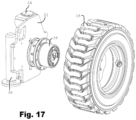
- Fig. 17 shows the details of the wheel assembly 21 with the wheel 18 removed, viewed from the outside.
- the wheel assembly 21 has hub 34 mounted thereon, with the wheel 18 being mountable on the hub.
- the lifting ram 36 and pivot 24 are also visible.
- the hub 34 includes an integrated gearbox and a spring applied hydraulically released (SAHR) parking brake. While the SAHR parking brake is mechanical, as already mentioned the skilled person may brake the wheels electrically or hydraulically.
- SAHR hydraulically released
- Fig. 18 is a flowchart of the steering control which is implemented in the truck using a combination of electronic and hydraulic controls.
- the driver operates electronic controls to select a forward mode or a sideward mode, and an electronic controller outputs appropriate control signals to control hydraulic valves to implement the chosen mode.
- Steering is mechanically implemented by a hydraulic circuit which receives steering inputs from a steering wheel under normal operation and which receives steering inputs from the electronic controller when implementing a mode change from forward to sideward mode or vice versa.
- Fig. 18 the procedure starts 50 with the truck in either forward or sideward mode, depending on the current wheel orientation. Describing first the situation with the truck in forward mode 52, the front wheel steering control locks the wheel into a straight-ahead position 54, and all steering signals are directed to the rear wheel steering cylinder 56. The controller checks for a mode change signal being input by the operator, decision 58. If no mode change signal is detected, the process loops back on the "no" branch and the truck remains in forward mode.
- step 60 the process moves to step 60 to perform the change from forward to sideward mode, as will be described in relation to Fig. 19 .
- step 62 the truck is in sideward mode.
- the rear wheel is locked in a transverse position 64, and all steering signals are now directed to the front steering wheels to steer the truck 66.
- the controller checks for a mode change signal being input by the operator, decision 68. If no mode change signal is detected, the process loops back on the "no" branch and the truck remains in sideward mode.
- step 70 the process moves to step 70 to perform the change from forward to sideward mode, as will be described in relation to Fig. 20 , following which the process will revert to step 52 with the truck once again in forward mode.
- the steering signals can either be controlled according to the forward mode branch of Fig. 18 or the sideward mode branch, with the transitions now described below in relation to Figs. 19 and 20 .
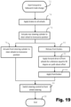
- the forward to sideward mode change is initiated, step 72.
- the brakes are applied on all wheels 74, and then the rear steering cylinder is actuated to steer the rear wheel into the transverse position 76.
- the front steering cylinder is actuated to steer the front wheels also to the transverse position 78.
- the front brakes are released 80, and forward drive is applied to the front wheels to drive them the required distance along the 90-degree arc that will translate them from the straight-ahead position to the sideward position 82.
- the front brakes are then applied 84, and the steering control is switched to front wheel steering 86, so that movements of the steering wheel will cause actuation of the front steering cylinders rather than the rear cylinder as happened before the mode change.
- the mode change process ends 88, the truck is operating in sideward mode.
- Fig. 20 shows the corresponding process for changing from sideward to rearward mode.
- the sideward to forward mode change is initiated, step 90.
- the brakes are applied on all wheels 92, and then the rear steering cylinder is actuated to steer the rear wheel into the straight-ahead position 94.
- the front steering cylinders are actuated to steer the front wheels also to the straight-ahead position 96.
- the front brakes are released 98, and forward drive is applied to the front wheels to drive them the required distance along the 90-degree arc that will translate them from the sideward position to the straight ahead position 100.
- the front brakes are then applied 102, and the steering control is switched to rear wheel steering 104, so that movements of the steering wheels will cause actuation of the rear steering cylinder rather than the front cylinders as happened before the mode change.
- the mode change process ends 106, the truck is operating in forward mode.
- Fig. 21 is a block diagram of the control system, in which a set of programmed controllers 110 operating in accordance with the flowcharts of Figs. 18-20 (appropriately programmed using stored program instructions in known manner) communicate drive signals to the drive motors at the left front wheel 112, right front wheel 114 and rear wheel 116. They also communicate brake signals to the front brakes 118 and the rear brake 120. Hydraulic steering controls 122 receive steering signals from the steering wheel and are hydraulically connected to the right front steering cylinder 124 (which in turn is hydraulically connected to the left front steering cylinder 126) and to the rear steering cylinder 128.
- the hydraulic steering controls 122 are provided in the form of valves and hydraulic circuits which are electromechanically switchable using signals from the programmed controllers 110 to operate the steering in sideward or forward mode. Depending on the state of the valves, hydraulic fluid may be directed to either the front cylinders 124, 126 or to the rear cylinder 128 when the steering wheel is turned.
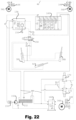
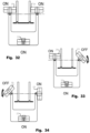
- Fig. 22 is a detailed schematic diagram of the steering and braking hydraulic circuits, while Figs. 23-25 show enlarged details of parts of Fig. 22 to better show the components illustrated.
- Fig. 22 there are four categories of hydraulic line connecting components. These lines are indicated (using dotted lead lines) with “SL” for steering lines, "BL” for brake lines, “PF” for pump feed lines, and "RET” for tank return lines.
- SL steering lines
- BL brake lines
- PF pump feed lines
- RET tank return lines
- Fig. 22 Certain components of the embodiments already described are visible in Fig. 22 .
- the front wheels are steered by respective steering cylinders 38L and 38R, and the rear wheel is steered by rear steering cylinder 56.
- the motors each drive a respective axle which is acted on by a respective SAHR brake, shown as right front brake 164, left front brake 166 and rear brake 168.
- the brakes are advantageously hub-mounted and integrated with the respective motor and gearbox for each wheel.
- Hydraulic fluid is supplied by a pump 150 fed from a tank 152.
- a filter (unlabelled but shown as a diamond bisected by a line) is visible at the tank outlet to the pump.
- the fluid for the steering circuit passes through a non-return valve 153 and is then fed into a steering motor 154 having a shaft 156 connected to a steering wheel.
- a six-port diverter valve 158 receives the steering lines SL from the steering motor 154, and this valve is operable as previously described to direct the steering control to either the rear steering cylinder 56 or the front steering cylinders 38L, 38R. It can be seen that the front steering cylinders 38L, 38R are series connected in a push-pull arrangement so that they operate together in a synchronised manner.
- Fig. 23 shows the steering motor 154, steering shaft 156 and diverter valve 158 in greater detail.
- the steering circuit also includes an electrically controlled valve bank section 160 which performs the operation to change the wheel orientation from forward to sideward mode and vice versa, as shown in greater detail in Fig. 24 , and previously described in relation to Figs. 19 and 20 .
- the braking circuit is supplied with hydraulic fluid also by pump 150, via a branch that leads to a pressure reducing valve 162 to reduce the pressure from the pump to the lower pressure required by the brakes.
- a front brake valve 170 and a rear brake valve 172 are independently operable to release the pair of front brakes 164, 166 or the rear brake 168 (recalling that in this embodiment the brakes are spring applied but hydraulically released).
- the valves 170, 172 are electrically controllable to apply and release the brakes both under operator control and under control of the programmable controller to carry out the sequence of brake applications and releases described in relation to Figs. 19 and 20 .
- the pressure reducing valve 162, rear brake valve 172, rear motor 34 and rear brake 168 can be seen in greater detail in Fig. 25 .
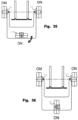
- Figs. 26-36 show the truck of Fig. 1 during a mode change operation with a different sequence of operations from that described previously.
- the truck transitions from forward mode ( Fig. 26 ) to sideward mode ( Fig. 31 ), and then in Figs. 32-35 the truck transitions from sideward mode ( Fig. 32 ) to forward mode ( Fig. 36 ).
- the word “ON” or “OFF” beside each of the wheels 18, 20, 22 indicates whether a respective brake, which can be independently applied to or released from that wheel under the control of the controller that sequences the mode change operation, is applied ("ON") or released ("OFF”).
- Fig. 26 the truck is seen in its forward mode, prior to the mode change operation.
- mode change is initiated, all of the brakes are applied, as can be seen from the indication "ON".
- Fig. 27 the rear wheel 22 begins to rotate about its vertical axis. Because the axis of pivoting rotation passes through the point of contact with the ground, the brake can remain applied to rear wheel 22, and at the end of this rotation as seen in Fig. 28 the rear wheel is transverse to the main axis of symmetry of the truck.
- Fig. 29 the brake is released from front left wheel 18, and the electric motor that drives the pivoting rotation of the left front wheel assembly is activated to cause the transition from the forward orientation of Fig. 28 to the sideward orientation achieved in Fig. 30 .
- the left front wheel 18 may be in a freewheel state as it follows the arcuate path about the pivot point of the wheel assembly with the chassis.
- the feature of applying drive to the wheel to match the speed of rotation and the arcuate path length is not essential in this embodiment.
- the embodiment can be modified to incorporate the application of positive drive to the wheel as the wheel assembly is being rotated, at the option of the designer of the control system. It will be appreciated that the controller can be simpler if it does not include the functionality of positively driving the wheel along the arcuate path as the wheel assembly is pivoted, but on the other hand the highest degree of control is achieved by adding positive drive to this embodiment also.
- Fig. 30 shows the transition of the right front wheel 20, wherein the brake has now been applied to the left front wheel 18 which has completed its transition, and the brake is released from the right front wheel 20 in order for it to be pivoted by an electric motor acting on the right front wheel assembly and to rotate in freewheel state along an arcuate path to complete the transition to sideward mode.
- an electric motor acting on the right front wheel assembly and to rotate in freewheel state along an arcuate path to complete the transition to sideward mode.
- Fig. 31 shows the end of the mode change operation, with all three wheels in sideward orientation and all three wheels braked in readiness for resumption of sideward driving control being applied.
- Fig. 32 shows the truck at the beginning of the reverse operation, from sideward to forward mode. Because all three wheels have their brakes applied in preparation for this operation, and all three wheels are transverse to the truck's main axis, Fig. 32 is indistinguishable from Fig. 31 .
- Figs. 33, 34 and 35 respectively show the reverse operations from Figs. 30, 29 and 27 .
- each front wheel in turn has its brake released, with the other two wheels having their brakes applied, and the unbraked wheel assembly is then pivoted about its respective pivot point and is pivotably rotated back to the forward position before applying the brake once more.
- the rear wheel assembly 22 is pivoted with its brake applied ( Fig. 35 ) to arrive at the final position in Fig. 36 .
Landscapes
- Engineering & Computer Science (AREA)
- Transportation (AREA)
- Structural Engineering (AREA)
- Mechanical Engineering (AREA)
- Chemical & Material Sciences (AREA)
- Combustion & Propulsion (AREA)
- Civil Engineering (AREA)
- Life Sciences & Earth Sciences (AREA)
- Geology (AREA)
- Steering-Linkage Mechanisms And Four-Wheel Steering (AREA)
- Handcart (AREA)
Applications Claiming Priority (3)
| Application Number | Priority Date | Filing Date | Title |
|---|---|---|---|
| GBGB2101426.1A GB202101426D0 (en) | 2021-02-02 | 2021-02-02 | Steering systems for lift trucks |
| PCT/EP2022/050247 WO2022167171A1 (fr) | 2021-02-02 | 2022-01-07 | Systèmes de direction pour des chariots élévateurs |
| EP22700135.1A EP4288326B1 (fr) | 2021-02-02 | 2022-01-07 | Systèmes de direction pour des chariots élévateurs |
Related Parent Applications (2)
| Application Number | Title | Priority Date | Filing Date |
|---|---|---|---|
| EP22700135.1A Division-Into EP4288326B1 (fr) | 2021-02-02 | 2022-01-07 | Systèmes de direction pour des chariots élévateurs |
| EP22700135.1A Division EP4288326B1 (fr) | 2021-02-02 | 2022-01-07 | Systèmes de direction pour des chariots élévateurs |
Publications (3)
| Publication Number | Publication Date |
|---|---|
| EP4375165A2 true EP4375165A2 (fr) | 2024-05-29 |
| EP4375165A3 EP4375165A3 (fr) | 2024-10-30 |
| EP4375165B1 EP4375165B1 (fr) | 2026-04-15 |
Family
ID=74865189
Family Applications (2)
| Application Number | Title | Priority Date | Filing Date |
|---|---|---|---|
| EP24169392.8A Active EP4375165B1 (fr) | 2021-02-02 | 2022-01-07 | Systèmes de direction pour chariots élévateurs |
| EP22700135.1A Active EP4288326B1 (fr) | 2021-02-02 | 2022-01-07 | Systèmes de direction pour des chariots élévateurs |
Family Applications After (1)
| Application Number | Title | Priority Date | Filing Date |
|---|---|---|---|
| EP22700135.1A Active EP4288326B1 (fr) | 2021-02-02 | 2022-01-07 | Systèmes de direction pour des chariots élévateurs |
Country Status (5)
| Country | Link |
|---|---|
| US (1) | US12589800B2 (fr) |
| EP (2) | EP4375165B1 (fr) |
| CN (1) | CN116848038A (fr) |
| GB (1) | GB202101426D0 (fr) |
| WO (1) | WO2022167171A1 (fr) |
Families Citing this family (3)
| Publication number | Priority date | Publication date | Assignee | Title |
|---|---|---|---|---|
| GB201901106D0 (en) * | 2019-01-28 | 2019-03-13 | Combilift | Tractor units for transporting elongated loads |
| JP7806658B2 (ja) * | 2022-11-09 | 2026-01-27 | 株式会社豊田自動織機 | 産業車両 |
| GB202305983D0 (en) * | 2023-04-24 | 2023-06-07 | Combilift | Seat system for a vehicle for lifting and moving loads |
Citations (1)
| Publication number | Priority date | Publication date | Assignee | Title |
|---|---|---|---|---|
| WO2003059799A1 (fr) | 2002-01-02 | 2003-07-24 | Combilift Research & Development Limited | Chariot elevateur a fourche quadri-directionnel |
Family Cites Families (13)
| Publication number | Priority date | Publication date | Assignee | Title |
|---|---|---|---|---|
| JPH0556755U (ja) * | 1991-12-27 | 1993-07-27 | 東急車輛製造株式会社 | 高所作業車 |
| EP0712805B1 (fr) * | 1993-05-18 | 2000-08-02 | Nippon Yusoki Co.,Ltd | Chariot élévateur à longue portée |
| JP2002046996A (ja) * | 2000-08-01 | 2002-02-12 | Tcm Corp | 横行システムを持った作業車両 |
| FR2900382B1 (fr) * | 2006-04-26 | 2009-02-27 | Benotec Soc Par Actions Simpli | Chariot de manutention a au moins trois roues directrices |
| IES20070379A2 (en) * | 2007-05-24 | 2008-01-23 | Martin Mcvicar | Three-wheel forklift truck |
| JP5992237B2 (ja) * | 2012-07-13 | 2016-09-14 | Ntn株式会社 | 転舵アシスト制御装置 |
| GB2510896B (en) * | 2013-02-18 | 2015-11-25 | Combilift | Load carrying trucks |
| CN106476888B (zh) * | 2016-10-28 | 2019-05-21 | 东莞市强乐塑胶制品有限公司 | 万向车 |
| GB2571736A (en) * | 2018-03-06 | 2019-09-11 | Combilift | Hydraulic steering systems for vehicle wheels |
| US20210402875A1 (en) * | 2020-06-25 | 2021-12-30 | Xuan Chieu Pham | Automobile with Extended 90-Degree Steering Range for Parallel Parking or Other Uses |
| KR20250028785A (ko) * | 2023-08-22 | 2025-03-04 | 현대자동차주식회사 | 독립 조향장치 미세조향 제어방법 |
| JP7842071B2 (ja) * | 2023-11-20 | 2026-04-07 | 三菱ロジスネクスト株式会社 | 無人搬送車 |
| CN120270334A (zh) * | 2024-01-08 | 2025-07-08 | 中国农业机械化科学研究院集团有限公司 | 一种模块化农机作业平台的多模式转向及切换方法 |
-
2021
- 2021-02-02 GB GBGB2101426.1A patent/GB202101426D0/en not_active Ceased
-
2022
- 2022-01-07 US US18/275,460 patent/US12589800B2/en active Active
- 2022-01-07 WO PCT/EP2022/050247 patent/WO2022167171A1/fr not_active Ceased
- 2022-01-07 EP EP24169392.8A patent/EP4375165B1/fr active Active
- 2022-01-07 CN CN202280012992.2A patent/CN116848038A/zh active Pending
- 2022-01-07 EP EP22700135.1A patent/EP4288326B1/fr active Active
Patent Citations (1)
| Publication number | Priority date | Publication date | Assignee | Title |
|---|---|---|---|---|
| WO2003059799A1 (fr) | 2002-01-02 | 2003-07-24 | Combilift Research & Development Limited | Chariot elevateur a fourche quadri-directionnel |
Also Published As
| Publication number | Publication date |
|---|---|
| EP4288326B1 (fr) | 2025-03-05 |
| EP4288326C0 (fr) | 2025-03-05 |
| EP4375165B1 (fr) | 2026-04-15 |
| US20240109584A1 (en) | 2024-04-04 |
| GB202101426D0 (en) | 2021-03-17 |
| EP4288326A1 (fr) | 2023-12-13 |
| EP4375165A3 (fr) | 2024-10-30 |
| WO2022167171A1 (fr) | 2022-08-11 |
| US12589800B2 (en) | 2026-03-31 |
| CN116848038A (zh) | 2023-10-03 |
Similar Documents
| Publication | Publication Date | Title |
|---|---|---|
| EP4375165A2 (fr) | Systèmes de direction pour chariots élévateurs | |
| US7878291B2 (en) | Rear axle steering system for a mobile crane | |
| JP2667879B2 (ja) | 自己舵取り車軸組立体 | |
| EP1401697A1 (fr) | Vehicule a rayon de braquage nul a roues orientables | |
| US20010040057A1 (en) | Multi-wheel vehicle with transmission for driving-steering | |
| CN109501855B (zh) | 一种多模式转向系统 | |
| JPS5815341B2 (ja) | 車輌用ステアリングアッセンブリ | |
| US5013057A (en) | Method of controlling a transport means and a transport means for effecting the method | |
| HK40111709A (en) | Steering systems for lift trucks | |
| HK40104928B (en) | Steering systems for lift trucks | |
| HK40104928A (en) | Steering systems for lift trucks | |
| EP1502839B1 (fr) | Tracteur articulé avec roues avant orientables | |
| JP3432309B2 (ja) | 油圧駆動式車両の駆動装置 | |
| US6378641B1 (en) | Vehicle equipped with turning mechanism | |
| US20130277136A1 (en) | Method for unobtrusive adaptation to enable power steering in vintage cars | |
| JP2001301635A (ja) | 運搬用車両 | |
| KR100331430B1 (ko) | 자동차용 주차 보조 장치 | |
| US20250178666A1 (en) | Steering system for a mobile work machine | |
| US3998289A (en) | Brake system for an articulated vehicle | |
| KR200331849Y1 (ko) | 링크식 후륜 강제조향장치 | |
| JPS59140174A (ja) | 後二軸型車両に使用されるステアリング系統 | |
| AU2005235431B2 (en) | Improved off road vehicle | |
| WO2012044210A1 (fr) | Procédé de freinage d'un véhicule et véhicule employant ce procédé | |
| JPH03248968A (ja) | 車輌の前輪操舵方法および前輪操舵装置 | |
| JPH01226477A (ja) | 回転半径の小さな自動車および旋回方法 |
Legal Events
| Date | Code | Title | Description |
|---|---|---|---|
| PUAI | Public reference made under article 153(3) epc to a published international application that has entered the european phase |
Free format text: ORIGINAL CODE: 0009012 |
|
| STAA | Information on the status of an ep patent application or granted ep patent |
Free format text: STATUS: THE APPLICATION HAS BEEN PUBLISHED |
|
| AC | Divisional application: reference to earlier application |
Ref document number: 4288326 Country of ref document: EP Kind code of ref document: P |
|
| AK | Designated contracting states |
Kind code of ref document: A2 Designated state(s): AL AT BE BG CH CY CZ DE DK EE ES FI FR GB GR HR HU IE IS IT LI LT LU LV MC MK MT NL NO PL PT RO RS SE SI SK SM TR |
|
| REG | Reference to a national code |
Ref legal event code: R079 Ref country code: DE Ref document number: 602022034846 Country of ref document: DE Free format text: PREVIOUS MAIN CLASS: B62D0009000000 Ipc: B62D0007150000 |
|
| PUAL | Search report despatched |
Free format text: ORIGINAL CODE: 0009013 |
|
| STAA | Information on the status of an ep patent application or granted ep patent |
Free format text: STATUS: REQUEST FOR EXAMINATION WAS MADE |
|
| AK | Designated contracting states |
Kind code of ref document: A3 Designated state(s): AL AT BE BG CH CY CZ DE DK EE ES FI FR GB GR HR HU IE IS IT LI LT LU LV MC MK MT NL NO PL PT RO RS SE SI SK SM TR |
|
| RIC1 | Information provided on ipc code assigned before grant |
Ipc: B62D 9/00 20060101ALN20240925BHEP Ipc: B66F 9/075 20060101ALI20240925BHEP Ipc: B62D 7/15 20060101AFI20240925BHEP |
|
| 17P | Request for examination filed |
Effective date: 20241015 |
|
| RBV | Designated contracting states (corrected) |
Designated state(s): AL AT BE BG CH CY CZ DE DK EE ES FI FR GB GR HR HU IE IS IT LI LT LU LV MC MK MT NL NO PL PT RO RS SE SI SK SM TR |
|
| REG | Reference to a national code |
Ref country code: HK Ref legal event code: DE Ref document number: 40111709 Country of ref document: HK |
|
| GRAP | Despatch of communication of intention to grant a patent |
Free format text: ORIGINAL CODE: EPIDOSNIGR1 |
|
| STAA | Information on the status of an ep patent application or granted ep patent |
Free format text: STATUS: GRANT OF PATENT IS INTENDED |
|
| INTG | Intention to grant announced |
Effective date: 20251111 |
|
| RIC1 | Information provided on ipc code assigned before grant |
Ipc: B62D 7/15 20060101AFI20251031BHEP Ipc: B66F 9/075 20060101ALI20251031BHEP Ipc: B62D 9/00 20060101ALN20251031BHEP |
|
| GRAS | Grant fee paid |
Free format text: ORIGINAL CODE: EPIDOSNIGR3 |
|
| GRAA | (expected) grant |
Free format text: ORIGINAL CODE: 0009210 |
|
| STAA | Information on the status of an ep patent application or granted ep patent |
Free format text: STATUS: THE PATENT HAS BEEN GRANTED |
|
| AC | Divisional application: reference to earlier application |
Ref document number: 4288326 Country of ref document: EP Kind code of ref document: P |
|
| AK | Designated contracting states |
Kind code of ref document: B1 Designated state(s): AL AT BE BG CH CY CZ DE DK EE ES FI FR GB GR HR HU IE IS IT LI LT LU LV MC MK MT NL NO PL PT RO RS SE SI SK SM TR |
|
| REG | Reference to a national code |
Ref country code: CH Ref legal event code: F10 Free format text: ST27 STATUS EVENT CODE: U-0-0-F10-F00 (AS PROVIDED BY THE NATIONAL OFFICE) Effective date: 20260415 |
|
| REG | Reference to a national code |
Ref country code: DE Ref legal event code: R096 Ref document number: 602022034846 Country of ref document: DE |