EP4378779A1 - Antriebssteuerungsvorrichtung für ein fahrzeug - Google Patents
Antriebssteuerungsvorrichtung für ein fahrzeug Download PDFInfo
- Publication number
- EP4378779A1 EP4378779A1 EP23205655.6A EP23205655A EP4378779A1 EP 4378779 A1 EP4378779 A1 EP 4378779A1 EP 23205655 A EP23205655 A EP 23205655A EP 4378779 A1 EP4378779 A1 EP 4378779A1
- Authority
- EP
- European Patent Office
- Prior art keywords
- vehicle
- function
- lane
- driving
- threshold value
- Prior art date
- Legal status (The legal status is an assumption and is not a legal conclusion. Google has not performed a legal analysis and makes no representation as to the accuracy of the status listed.)
- Granted
Links
Images


Classifications
-
- B—PERFORMING OPERATIONS; TRANSPORTING
- B60—VEHICLES IN GENERAL
- B60W—CONJOINT CONTROL OF VEHICLE SUB-UNITS OF DIFFERENT TYPE OR DIFFERENT FUNCTION; CONTROL SYSTEMS SPECIALLY ADAPTED FOR HYBRID VEHICLES; ROAD VEHICLE DRIVE CONTROL SYSTEMS FOR PURPOSES NOT RELATED TO THE CONTROL OF A PARTICULAR SUB-UNIT
- B60W30/00—Purposes of road vehicle drive control systems not related to the control of a particular sub-unit, e.g. of systems using conjoint control of vehicle sub-units
- B60W30/08—Active safety systems predicting or avoiding probable or impending collision or attempting to minimise its consequences
- B60W30/09—Taking automatic action to avoid collision, e.g. braking and steering
-
- B—PERFORMING OPERATIONS; TRANSPORTING
- B60—VEHICLES IN GENERAL
- B60W—CONJOINT CONTROL OF VEHICLE SUB-UNITS OF DIFFERENT TYPE OR DIFFERENT FUNCTION; CONTROL SYSTEMS SPECIALLY ADAPTED FOR HYBRID VEHICLES; ROAD VEHICLE DRIVE CONTROL SYSTEMS FOR PURPOSES NOT RELATED TO THE CONTROL OF A PARTICULAR SUB-UNIT
- B60W30/00—Purposes of road vehicle drive control systems not related to the control of a particular sub-unit, e.g. of systems using conjoint control of vehicle sub-units
- B60W30/10—Path keeping
- B60W30/12—Lane keeping
-
- B—PERFORMING OPERATIONS; TRANSPORTING
- B60—VEHICLES IN GENERAL
- B60W—CONJOINT CONTROL OF VEHICLE SUB-UNITS OF DIFFERENT TYPE OR DIFFERENT FUNCTION; CONTROL SYSTEMS SPECIALLY ADAPTED FOR HYBRID VEHICLES; ROAD VEHICLE DRIVE CONTROL SYSTEMS FOR PURPOSES NOT RELATED TO THE CONTROL OF A PARTICULAR SUB-UNIT
- B60W30/00—Purposes of road vehicle drive control systems not related to the control of a particular sub-unit, e.g. of systems using conjoint control of vehicle sub-units
- B60W30/14—Adaptive cruise control
- B60W30/143—Speed control
-
- B—PERFORMING OPERATIONS; TRANSPORTING
- B60—VEHICLES IN GENERAL
- B60W—CONJOINT CONTROL OF VEHICLE SUB-UNITS OF DIFFERENT TYPE OR DIFFERENT FUNCTION; CONTROL SYSTEMS SPECIALLY ADAPTED FOR HYBRID VEHICLES; ROAD VEHICLE DRIVE CONTROL SYSTEMS FOR PURPOSES NOT RELATED TO THE CONTROL OF A PARTICULAR SUB-UNIT
- B60W30/00—Purposes of road vehicle drive control systems not related to the control of a particular sub-unit, e.g. of systems using conjoint control of vehicle sub-units
- B60W30/14—Adaptive cruise control
- B60W30/16—Control of distance between vehicles, e.g. keeping a distance to preceding vehicle
-
- B—PERFORMING OPERATIONS; TRANSPORTING
- B60—VEHICLES IN GENERAL
- B60W—CONJOINT CONTROL OF VEHICLE SUB-UNITS OF DIFFERENT TYPE OR DIFFERENT FUNCTION; CONTROL SYSTEMS SPECIALLY ADAPTED FOR HYBRID VEHICLES; ROAD VEHICLE DRIVE CONTROL SYSTEMS FOR PURPOSES NOT RELATED TO THE CONTROL OF A PARTICULAR SUB-UNIT
- B60W30/00—Purposes of road vehicle drive control systems not related to the control of a particular sub-unit, e.g. of systems using conjoint control of vehicle sub-units
- B60W30/18—Propelling the vehicle
- B60W30/18009—Propelling the vehicle related to particular drive situations
- B60W30/18163—Lane change; Overtaking manoeuvres
-
- B—PERFORMING OPERATIONS; TRANSPORTING
- B60—VEHICLES IN GENERAL
- B60W—CONJOINT CONTROL OF VEHICLE SUB-UNITS OF DIFFERENT TYPE OR DIFFERENT FUNCTION; CONTROL SYSTEMS SPECIALLY ADAPTED FOR HYBRID VEHICLES; ROAD VEHICLE DRIVE CONTROL SYSTEMS FOR PURPOSES NOT RELATED TO THE CONTROL OF A PARTICULAR SUB-UNIT
- B60W50/00—Details of control systems for road vehicle drive control not related to the control of a particular sub-unit, e.g. process diagnostic or vehicle driver interfaces
- B60W50/08—Interaction between the driver and the control system
- B60W50/082—Selecting or switching between different modes of propelling
-
- B—PERFORMING OPERATIONS; TRANSPORTING
- B60—VEHICLES IN GENERAL
- B60W—CONJOINT CONTROL OF VEHICLE SUB-UNITS OF DIFFERENT TYPE OR DIFFERENT FUNCTION; CONTROL SYSTEMS SPECIALLY ADAPTED FOR HYBRID VEHICLES; ROAD VEHICLE DRIVE CONTROL SYSTEMS FOR PURPOSES NOT RELATED TO THE CONTROL OF A PARTICULAR SUB-UNIT
- B60W50/00—Details of control systems for road vehicle drive control not related to the control of a particular sub-unit, e.g. process diagnostic or vehicle driver interfaces
- B60W50/08—Interaction between the driver and the control system
- B60W50/10—Interpretation of driver requests or demands
-
- B—PERFORMING OPERATIONS; TRANSPORTING
- B60—VEHICLES IN GENERAL
- B60W—CONJOINT CONTROL OF VEHICLE SUB-UNITS OF DIFFERENT TYPE OR DIFFERENT FUNCTION; CONTROL SYSTEMS SPECIALLY ADAPTED FOR HYBRID VEHICLES; ROAD VEHICLE DRIVE CONTROL SYSTEMS FOR PURPOSES NOT RELATED TO THE CONTROL OF A PARTICULAR SUB-UNIT
- B60W60/00—Drive control systems specially adapted for autonomous road vehicles
- B60W60/005—Handover processes
- B60W60/0053—Handover processes from vehicle to occupant
-
- B—PERFORMING OPERATIONS; TRANSPORTING
- B60—VEHICLES IN GENERAL
- B60W—CONJOINT CONTROL OF VEHICLE SUB-UNITS OF DIFFERENT TYPE OR DIFFERENT FUNCTION; CONTROL SYSTEMS SPECIALLY ADAPTED FOR HYBRID VEHICLES; ROAD VEHICLE DRIVE CONTROL SYSTEMS FOR PURPOSES NOT RELATED TO THE CONTROL OF A PARTICULAR SUB-UNIT
- B60W2520/00—Input parameters relating to overall vehicle dynamics
- B60W2520/10—Longitudinal speed
- B60W2520/105—Longitudinal acceleration
-
- B—PERFORMING OPERATIONS; TRANSPORTING
- B60—VEHICLES IN GENERAL
- B60W—CONJOINT CONTROL OF VEHICLE SUB-UNITS OF DIFFERENT TYPE OR DIFFERENT FUNCTION; CONTROL SYSTEMS SPECIALLY ADAPTED FOR HYBRID VEHICLES; ROAD VEHICLE DRIVE CONTROL SYSTEMS FOR PURPOSES NOT RELATED TO THE CONTROL OF A PARTICULAR SUB-UNIT
- B60W2540/00—Input parameters relating to occupants
- B60W2540/18—Steering angle
-
- B—PERFORMING OPERATIONS; TRANSPORTING
- B60—VEHICLES IN GENERAL
- B60W—CONJOINT CONTROL OF VEHICLE SUB-UNITS OF DIFFERENT TYPE OR DIFFERENT FUNCTION; CONTROL SYSTEMS SPECIALLY ADAPTED FOR HYBRID VEHICLES; ROAD VEHICLE DRIVE CONTROL SYSTEMS FOR PURPOSES NOT RELATED TO THE CONTROL OF A PARTICULAR SUB-UNIT
- B60W2552/00—Input parameters relating to infrastructure
- B60W2552/30—Road curve radius
-
- B—PERFORMING OPERATIONS; TRANSPORTING
- B60—VEHICLES IN GENERAL
- B60W—CONJOINT CONTROL OF VEHICLE SUB-UNITS OF DIFFERENT TYPE OR DIFFERENT FUNCTION; CONTROL SYSTEMS SPECIALLY ADAPTED FOR HYBRID VEHICLES; ROAD VEHICLE DRIVE CONTROL SYSTEMS FOR PURPOSES NOT RELATED TO THE CONTROL OF A PARTICULAR SUB-UNIT
- B60W2555/00—Input parameters relating to exterior conditions, not covered by groups B60W2552/00, B60W2554/00
- B60W2555/20—Ambient conditions, e.g. wind or rain
Definitions
- the present invention relates to a driving control apparatus for a vehicle, and more particularly, relates to vehicle driving control during the operation of an emergency avoidance control for avoiding a collision with another vehicle.
- An automatically lane keeping system or automated lane keeping system is known in which a vehicle is kept in a lane and is kept traveling at or below a predetermined speed by controlling the forward, backward, left, and right movements of the vehicle without requiring driver operations.
- the automated lane keeping system has an emergency maneuver (EM) function that shifts to emergency avoidance control for avoiding a collision when a collision with an obstacle is predicted, for example.
- the EM function is configured to combine the use of steering and deceleration at the maximum deceleration rate to eventually bring the vehicle to a stop, for example.
- an automated driving vehicle having an automated driving function that automatically drives the vehicle to follow a target path, and a preventive safety function that avoids hazards to the vehicle is disclosed in Patent Literature 2, for example. If imminent danger to the vehicle is predicted while automated driving is being executed, intervention of the preventive safety function in the automated driving is performed. However, if the automated driving system refuses intervention in automated driving in a normal state, intervention in automated driving is suspended.
- an automated lane keeping system is provided with an EM function that performs an emergency avoidance control when a collision with an obstacle is predicted. If the system is configured to determine an evacuation area after the shift to the EM function in the automated lane keeping system, and to guide the vehicle to a stop in the determined evacuation area, the actual start of evacuation operations will be delayed by the system processing time from the shift to the EM function to the determination of the evacuation area.
- the present invention was created in light of the actual conditions like the above-described, and the objective thereof is to make it possible to quickly perform an emergency avoidance control when shifting to an EM function in an automated lane keeping system.
- a driving control apparatus for a vehicle includes: an environmental condition estimating part including a surrounding recognition function for recognizing a driving lane of the vehicle, neighboring lanes, other vehicles in each of the lanes, and a surrounding environment, and a function for obtaining a state of movement of the vehicle; a path generating part configured to generate a target path on the basis of information obtained by the environmental condition estimating part; and a vehicle control part configured to perform speed control and steering control for the vehicle to follow the target path, the driving control apparatus for a vehicle having: an in-lane automated driving function that performs in-lane automated driving for maintaining a set speed if no other vehicle is present ahead in the lane of the vehicle and maintaining a set inter-vehicle distance if another vehicle is present ahead; and an EM function that executes an emergency avoidance control, including activation of emergency braking, if a collision with an obstacle present ahead in the lane of the vehicle is predicted, wherein: the path generating part has an evacuation area setting part that sets
- a driving control apparatus for a vehicle can start performing an emergency avoidance control quickly when shifting to an EM function in an automated lane keeping system.
- the driving control apparatus for a vehicle has the function of an automated lane keeping system (ALKS) that recognizes the position of the vehicle and the surrounding environment of the vehicle using external sensors such as radars and cameras, and controls vehicle speed and steering to perform automatic driving in a single lane at or below a predetermined speed (for example, 60 km/h).
- ALKS automated lane keeping system
- the ALKS is a system combining an adaptive cruise control system (ACCS) and a lane keeping assistance system (LKAS).
- the main functions of the ALKS include lane marking recognition, in-lane vehicle position recognition, target vehicle speed and target path generation, vehicle speed control and in-lane path following control, automated steering, and the like.
- vehicle speed control and in-lane path following control mean the control of vehicle speed and steering necessary to achieve a target vehicle speed and target path.
- Automated steering means that steering is performed using electric power steering with a steering torque necessary to achieve a target steering angle for path following.
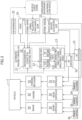
- a vehicle 1 provided with a driving control apparatus is provided with, in addition to typical automobile components such as an engine, a vehicle body, and tires, an external sensor 21 that detects the vehiclesurrounding environment, an internal sensor 22 that detects vehicle information, including the state of movement, a map information database 23, positioning means 24, a controller/actuator group for speed control and steering control, an ACC controller 15 for inter-vehicle distance control, an LKA controller 16 for lane keeping control, and an automated driving controller 10 for unifying the above to execute in-lane automated driving control, so that recognition, determination, and control conventionally performed by the driver are performed by the vehicle side.
- an external sensor 21 that detects the vehiclesurrounding environment
- an internal sensor 22 that detects vehicle information, including the state of movement
- a map information database 23 positioning means 24, a controller/actuator group for speed control and steering control, an ACC controller 15 for inter-vehicle distance control, an LKA controller 16 for lane keeping control, and an automated driving controller 10 for unifying the above to execute in-lane automated
- the controller/actuator group for speed control and steering control includes an electric power steering (EPS) controller 31 for steering control, an engine controller 32 for acceleration/deceleration rate control, and an ESP/ABS controller 33.
- EPS electric power steering
- An ESP includes an anti-lock braking system (ABS) to form a stability control system (vehicle behavior stabilization control system).
- the external sensor 21 is composed of a plurality of detection means for inputting external data such as image data or point cloud data, representing lane markings on a road defining the lane of the vehicle and neighboring lanes, and presence of, and relative distance from, obstacles such as other vehicles and people around the vehicle, into the automated driving controller 10.
- external data such as image data or point cloud data, representing lane markings on a road defining the lane of the vehicle and neighboring lanes, and presence of, and relative distance from, obstacles such as other vehicles and people around the vehicle
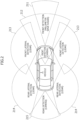
- the vehicle 1 is provided with a millimeter wave radar (211) and a camera (212) as front detection means 211 and 212, LIDARs (Laser Imaging Detection And Ranging) as front lateral detection means 213 and rear lateral detection means 214, and a camera (back camera) as rear detection means 215.
- the external sensor 21 is disposed to cover 360 degrees around the vehicle and enable detection of the positions of, and distances from, other vehicles, obstacles, and the like, and lane marking positions of the lane of the vehicle and the neighboring lanes, within a predetermined range in each of the front, rear, left, and right directions of the vehicle.
- a millimeter wave radar or LIDAR
- the internal sensor 22 is composed of a plurality of detection means, such as a vehicle speed sensor, a yaw rate sensor, and an acceleration sensor, to measure physical quantities representing the state of movement of the vehicle. As illustrated in Figure 3 , each of the measurement values from the internal sensor 22 is input into the automated driving controller 10, the ACC controller 15, the LKA controller 16, and the EPS controller 31, and is computationally processed together with input from the external sensor 21.
- detection means such as a vehicle speed sensor, a yaw rate sensor, and an acceleration sensor
- the external sensor 21 and the internal sensor 22 are configured to activate simultaneously with the startup of the vehicle 1 and to constantly monitor the surrounding environment and vehicle information.
- the automated driving controller 10 includes an environmental condition estimating part 11, a path generating part 12, and a vehicle control part 13, and includes a computer for executing functions as described below, that is constituted of ROM for storing programs and data, a CPU for performing computational processing, RAM for reading out the programs and data and storing dynamic data and computational processing results, an input/output interface, and the like.
- the environmental condition estimating part 11 acquires the absolute location of the vehicle 1 by matching the vehicle location information according to the positioning means 24 such as a global navigation satellite system (GNSS) with map information in the map information database 23.
- the environmental condition estimating part 11 estimates, on the basis of external data such as image data and point cloud data acquired by the external sensor 21, the positions of lane markings of the lane of the vehicle and the neighboring lanes, and the positions and speeds of other vehicles. Note that instead of acquiring the absolute location of the vehicle 1 on the basis of the vehicle location information according to the positioning means 24 and the map information in the map information database 23, the environmental condition estimating part 11 can also be configured to obtain the relative position of the vehicle 1 with respect to a lane marking with a neighboring lane obtained from the external sensor 21.
- GNSS global navigation satellite system
- the environmental condition estimating part 11 is further configured to determine whether an obstacle ahead in the lane of the vehicle is a stationary object or a moving object.
- a stationary object is an obstacle the absolute location of which is not moving, such as a parked vehicle, safety equipment for road construction, or the like, for example.
- a moving object is an obstacle the absolute location of which is moving, such as another vehicle ahead, a pedestrian, an oncoming vehicle, or the like, for example.
- An obstacle can be determined to be a stationary object or to be a moving object on the basis of the relative speed between the vehicle 1 and the obstacle, for example.
- an oncoming vehicle is a vehicle traveling in the opposite direction to the direction of travel of the vehicle 1, and in particular, is a vehicle traveling so as to approach the vehicle 1 in the lane in which the vehicle 1 is traveling.
- the determination of whether an obstacle is an oncoming vehicle can be made on the basis of, for example, information such as the absolute location of the vehicle 1, the positions of lane markings of the lane of the vehicle and the neighboring lanes, and the positions and speeds of other vehicles, which are obtained from the external sensor 21, the internal sensor 22, the map information database 23, and the positioning means 24. That is, the environmental condition estimating part 11 also functions as an oncoming vehicle detecting part.
- the environmental condition estimating part 11 detects the optical flow of obstacles existing ahead of the vehicle on the basis of image data of the area ahead of the vehicle acquired by the external sensor 21 (camera 212).
- Optical flow is a vector representation of the movement of an object between image frames in a plurality of temporally consecutive image frames in a video image. Therefore, by detecting the optical flow, the movement direction of an obstacle can be determined. If an obstacle is moving so as to approach the vehicle 1 in the lane of the vehicle, the environmental condition estimating part 11 can determine that the obstacle is an oncoming vehicle.
- the environmental condition estimating part 11 may also determine an oncoming vehicle on the basis of information obtained through vehicle-to-vehicle communication or infrastructure-to-vehicle communication.
- the environmental condition estimating part 11 acquires the state of movement of the vehicle from internal data measured by the internal sensor 22.
- the path generating part 12 is configured to generate a target path to a final destination from the vehicle location estimated by the environmental condition estimating part 11.
- the path generating part 12 includes an ALKS pathing, or path-setting, part 121 and an EM path-setting part 122.
- the ALKS path-setting part 121 In the state in which the ALKS is active, the ALKS path-setting part 121 generates a target path (target path for the ALKS) for automated driving in a single lane on the basis of the positions of lane markings of the neighboring lanes, the positions and speeds of other vehicles, the state of movement of the vehicle 1, and the like which are estimated by the environmental condition estimating part 11.
- the EM path-setting part 122 generates an emergency target path (target path for EM) to guide and bring the vehicle to a stop at the target stop position in the emergency avoidance control for avoiding a collision with an obstacle.
- the EM path-setting part 122 is further configured to pre-set an emergency evacuation area for setting a target stop position on the target path for the ALKS in case the emergency avoidance control is executed.
- the EM path-setting part 122 sets the target stop position according to the activation mode of the EM function as described later.
- the path generating part 12 is further configured to determine whether a poor visibility area, in which visibility is poor, exists on the target path on which the vehicle 1 travels.
- the vehicle control part 13 calculates a target vehicle speed and a target steering angle on the basis of the target path generated by the path generating part 12.
- the vehicle control part 13 transmits a speed command for constant-speed driving or inter-vehicle distance maintenance/following driving to the ACC controller 15, and transmits a steering angle command for path following to the EPS controller 31 via the LKA controller 16.
- the vehicle speed is also input into the EPS controller 31 and the ACC controller 15. Since the steering reaction force varies depending on the vehicle speed, the EPS controller 31 references a steering angle-steering torque map according to vehicle speed and transmits a torque command to a steering mechanism 41. By controlling an engine 42, a brake 43, and the steering mechanism 41 with the engine controller 32, the ESP/ABS controller 33, and the EPS controller 31, the movement of the vehicle 1 in the longitudinal direction and the lateral direction is controlled.
- the ALKS is a system combining an adaptive cruise control system (ACCS) and a lane keeping assistance system (LKAS), enabling automated lane keeping driving (automated in-lane driving) in the state in which the ACCS by the ACC controller 15 and the LKAS by the LKA controller 16 are both active.
- ACCS adaptive cruise control system
- LKAS lane keeping assistance system
- the path generating part 12 of the automated driving controller 10, specifically the ALKS path-setting part 121, generates a target path and a target vehicle speed for activating the ALKS on the basis of external information (lanes, vehicle location, the positions and speeds of other vehicles traveling in the vehicle's own driving lane and the neighboring lanes, and the presence or absence of pedestrians and other obstacles) acquired by the external sensor 21 and internal information (vehicle speed, yaw rate, acceleration rate) acquired by the internal sensor 22.
- external information lanes, vehicle location, the positions and speeds of other vehicles traveling in the vehicle's own driving lane and the neighboring lanes, and the presence or absence of pedestrians and other obstacles
- internal information vehicle speed, yaw rate, acceleration rate
- the vehicle control part 13 estimates the speed/attitude/lateral displacement of the vehicle ⁇ t seconds later based on the vehicle location and the movement characteristics of the vehicle, that is, from the relationship between the yaw rate ⁇ and the lateral acceleration rate (d 2 y/dt 2 ) produced by vehicle movement according to the front wheel steering angle ⁇ produced when steering torque T is imparted to the steering mechanism 41 while driving at the vehicle speed V.
- the vehicle control part 13 issues a steering angle command to the EPS controller 31 via the LKA controller 16 such that the lateral displacement will be yt ⁇ t seconds later, and issues a speed command to the ACC controller 15 such that a speed Vt will be obtained ⁇ t seconds later.
- the ACC controller 15, the LKA controller 16, the EPS controller 31, the engine controller 32, and the ESP/ABS controller 33 operate independently and irrespectively of the automated steering, but are also operable according to command inputs from the automated driving controller 10 while the ALKS is active.
- the ESP/ABS controller 33 Upon receiving a deceleration command from the ACC controller 15, the ESP/ABS controller 33 controls the vehicle speed by outputting a hydraulic command to the actuator and controlling the braking force of the brake 43. Also, upon receiving an acceleration/deceleration command from the ACC controller 15, the engine controller 32 controls the actuator output (throttle position) to thereby issue a torque command to the engine 42 so as to control the driving force and to control the vehicle speed.
- the adaptive cruise control system functions as a combination of hardware and software, such as a millimeter wave radar serving as the front detection means 211 included in the external sensor 21, the ACC controller 15, the engine controller 32, and the ESP/ABS controller 33.
- the ACCS is configured to perform constant-speed driving with the ACC set speed (set speed) treated as the target vehicle speed.
- the ACCS is configured to accelerate to a set speed at a set acceleration rate.
- the lane keeping assistance system detects the lane markings and the vehicle location by the environmental condition estimating part 11 of the automated driving controller 10 on the basis of image data obtained by the external sensor 21 (cameras 212 and 215), and performs steering control by the EPS controller 31 via the LKA controller 16 so as to be able to drive in the lane center.
- LKAS lane keeping assistance system
- the EPS controller 31 that has received a steering angle command from the LKA controller 16, references a map of vehicle speed-steering angle-steering torque to transmit a torque command to an actuator (EPS motor), and issues a front wheel steering angle to serve as the target for the steering mechanism 41.
- EPS motor actuator
- the ALKS executes an automated lane keeping function by combining longitudinal control (speed control and inter-vehicle distance control) by the ACC controller 15 and lateral control (steering control and lane keeping control) by the LKA controller 16.
- the emergency maneuver (EM) function is activated and the emergency avoidance control is executed.
- the EM function includes autonomous emergency braking (AEB) for collision avoidance or collision mitigation.
- TTC inter-vehicle distance/relative speed
- a poor visibility area refers to an area in which the degree of visibility of the road is less than a prescribed value and the visibility is poor.
- the degree of visibility can be expressed as a visible distance expressing the distance from the vehicle 1 to a visible obstacle on the road, for example.
- the visible distance refers to the distance along the target path from the current location of the vehicle 1 to the obstacle present at the farthest location that is visible on the target path. Visibility can be determined to be better if the visible distance is farther, and to be worse if the visible distance is nearer.
- How far away from the vehicle 1 the obstacle can be seen is determined by not only the shape of the road, but also the sizes and shapes of structures existing between the vehicle 1 and the obstacle. For example, distant obstacles are visible if there are no structures in the vicinity, even on a steeply curving road with a small radius of curvature. On the other hand, if a sidewall exists along the road, obstacles may be obscured by the sidewall, even on a gently curving road with a large radius of curvature.
- the visible distance at which an obstacle is visible is determined on the basis of road information about the road alignment, landmarks that exist along the road, and the like.
- Information about road alignment is information about the shape of the road and includes the radius of curvature of the road and the vertical grade, for example.
- Landmarks include both natural landforms and manmade structures, and information about landmarks that exist along the road includes information about the shapes, sizes, and the like of structures that exist near the road, such as sidewalls and buildings, for example.
- the prescribed value for determining the degree of visibility can be defined as, for example, the braking distance required for the vehicle 1 to come to a braking stop without colliding with an obstacle after detecting the obstacle on the target path.
- the braking distance is determined on the basis of road information about the radius of curvature and vertical grade of the road, landmarks that exist along the road, and the like, as well as speed limit information on the target path.
- An area in which the visible distance is less than the braking distance is determined to be a poor visibility area in which the degree of visibility of the road is poor.
- the EM path-setting part 122 of the path generating part 12 of the automated driving controller 10 is configured to set, on the basis of the location of the vehicle acquired by the environmental condition estimating part 11 and map information on the vehicle surroundings acquired from the map information database 23, an emergency evacuation area on the target path in case of activation of the EM function while the automated lane keeping driving by the ALKS is being executed. That is, the EM path-setting part 122 also functions as an evacuation area setting part.
- an emergency evacuation area is configured to be set when a poor visibility area described later is determined to exist, in consideration of the possibility that there may be a delay in the detection, by the system, of conditions ahead in the lane of the vehicle on a road with poor visibility. Note that no emergency evacuation area is set in an area with good visibility.
- An emergency evacuation area is set in an area on the side edge of the road on which the vehicle 1 travels. That is, in the case of left-hand traffic, an emergency evacuation area is set on the left side of the road, including an area such as a shoulder or a roadside strip outside the lane in which the vehicle 1 travels, whereas in the case of right-hand traffic, an emergency evacuation area is set on the right side of the road, including an area such as a shoulder or a roadside strip outside the lane in which the vehicle 1 travels.
- the emergency evacuation area is set as an area along the side edge of the road, with a predetermined width that includes the lateral width (vehicle width) of the vehicle 1, for example.
- the EM path-setting part 122 estimates, on the basis of the vehicle location and the map information on the vehicle surroundings, the road shape on which the vehicle 1 is traveling and sets an emergency evacuation area corresponding to the road shape.
- the emergency evacuation area is set on the target path ahead in the direction of travel of the vehicle, and is constantly updated as the vehicle 1 moves.
- the environmental condition estimating part 11 of the automated driving controller 10 constantly monitors whether the driving state of the vehicle, the surrounding environmental conditions, the driver state, and the like are maintained within an operational design domain (ODD) of the system on the basis of the surrounding environment acquired by the external sensor 21, the vehicle information acquired by the internal sensor 22, and the like.
- ODD operational design domain
- Figure 4 illustrates state transitions of control in the ALKS.
- the environmental condition estimating part 11 determines whether there are deviations from the system operating conditions and detects whether there are abnormalities or faults in the system, on the basis of the driving state of the vehicle, the surrounding environmental conditions, the driver state, and the like.
- an operation takeover request (transition demand (TD)) is issued from the system to the driver. If the driver takes over driving operations within a prescribed time (for example, 10 seconds) after the operation takeover request (TD), automated lane keeping driving transitions to manual driving (the ALKS stops).
- TD transition demand
- a minimal risk maneuver (MRM) function is activated and risk minimization control is performed.
- the MRM function means a function that automatically shifts to a minimal risk condition when the driver is unable to take over operations.
- the MRM includes control to evacuate to the shoulder through automated steering or to decelerate to a stop in the lane (safe stop) by the automated driving controller 10.
- the environmental condition estimating part 11 determines that a serious fault has occurred in the system (such as engine hydraulic pressure reduction, engine water temperature rise, or brake system abnormality that may cause an accident, a fire, or the like) while the ALKS is active, the operation takeover request (TD) is not made so that the MRM function is activated immediately to perform the risk minimization control.
- a serious fault such as engine hydraulic pressure reduction, engine water temperature rise, or brake system abnormality that may cause an accident, a fire, or the like
- the EM function described above is activated and the emergency avoidance control is executed.
- the brake 43 is controlled via the ACC controller 15 and the steering mechanism 41 is controlled via the LKA controller 16 so that the vehicle 1 is guided to a stop at the target stop position set by the EM path-setting part 122.
- the driving control apparatus described above is configured to allow an override due to a control intervention by the driver while the ALKS is active or while the EM function and the MRM function are active. That is, the override function is a function that stops active functions and transfers control or authority to the driver if there a control intervention equal to or greater than a predetermined threshold by the driver while the ALKS, the EM function, and the MRM function are active.
- override threshold values acceleration/deceleration override threshold values related to acceleration/deceleration operations are set to, for example, an accelerator control input (engine torque command value) or brake control input (ESP hydraulic command value) at which the driver is judged to have intentionally performed an acceleration/deceleration operation according to the acceleration/deceleration characteristics and driving state of the vehicle.
- the override threshold (steering override threshold) related to a steering operation is set according to the steering characteristics and the driving state of the vehicle 1, for example. It can be configured such that the manual steering control 34 and the manual acceleration/deceleration controls 35, 36 are detected by the internal sensor 22, for example.
- the override function is executable even while the EM function is active. If there is a switch from the state in which automated lane keeping driving was being performed by the ALKS to a hazard avoidance mode in which the EM function is executed, there is a possibility that the emergency autonomous braking by the EM function may cause the driver to panic. Consequently, if an excessive override, such as excessive acceleration/deceleration operations or excessive steering operations, is performed by the panicked driver, the behavior of the vehicle 1 may become unstable or the vehicle 1 may suddenly approach a nearby obstacle or nearby structure.
- the driving control apparatus if the EM function is activated while the ALKS is active, an override due to excessive driving operations by the driver is suppressed by changing the override threshold values to values greater than normal. Furthermore, if the EM function is activated due to the detection of a moving object, the override threshold values are set to even greater values.
- the avoidance control of the EM function by the automated driving controller 10 is continued even when a driver, being panicked by the appearance of a moving object such as an oncoming vehicle, for example, performs excessive acceleration/deceleration operations or excessive steering operation, which would normally cause the EM function to be overridden and shifted to the manual driving mode.
- a driver being panicked by the appearance of a moving object such as an oncoming vehicle, for example, performs excessive acceleration/deceleration operations or excessive steering operation, which would normally cause the EM function to be overridden and shifted to the manual driving mode.
- the override threshold values include the acceleration/deceleration override threshold values related to acceleration/deceleration operations and the steering override threshold value related to steering operation.
- the acceleration/deceleration override threshold values include an accelerator override threshold value related to an accelerator operation and a brake override threshold value related to a brake operation.
- an accelerator override is executed.
- the accelerator operation by the driver is given priority over the automated lane keeping driving by the ALKS.
- an engine torque command value obtained from an engine torque map set according to the vehicle speed and the gear stage is set as an accelerator override threshold value OEd.
- an ESP hydraulic command value that causes a deceleration with respect to constant-speed driving or inter-vehicle distance maintaining/following driving is given by a brake operation by the driver, a brake override is executed.
- the brake operation by the driver is given priority over the automated lane keeping driving by the ALKS.
- an ESP hydraulic command value that causes a deceleration by a speed of 2 km/h with respect to constant-speed driving or inter-vehicle distance maintaining/following driving or an ESP hydraulic command value that corresponds to a deceleration rate of 0.2 m/s 2 with respect to an ACC set acceleration is set as a brake override threshold value OPd.
- a threshold value for the case of additive steering and a threshold value for the case of subtractive steering are set separately.
- a steering torque corresponding to a steering angle at which a virtual lateral displacement y't for reaching a virtual lateral position after t seconds becomes yt+ ⁇ is set as the steering override threshold value OTd.
- ⁇ is a constant determined on the basis of the vehicle speed
- a value that can be determined not to be very small and is applied in a direction of reducing the steering torque to a value (steering torque target value) obtained by converting a steering angle at which the virtual lateral displacement y't for reaching the virtual lateral position after t seconds becomes yt+ ⁇ into the steering torque is set as the steering override threshold value OTd.
- the value can be determined as being very small or not on the basis of the steering angle and the steering angle speed, for example.
- An accelerator override threshold value OEema when the EM function is activated due to a stationary object being detected is set to a value greater than the normal accelerator override threshold value OEd described above.
- an engine torque command value selected from the range of 120%-250%, preferably 150%-220%, of the normal accelerator override threshold value OEd can be set as the accelerator override threshold value OEema when the EM is activated due to a stationary object. That is, OEema > OEd.
- a brake override threshold value OPema when the EM function is activated due to a stationary object being detected is set to a value greater than the normal brake override threshold value OPd described above.
- an ESP hydraulic command value selected from the range of 120%-250%, preferably 150%-220%, of the normal brake override threshold value OPd can be set as the brake override threshold value OPema when the EM is activated due to a stationary object. That is, OPema > OPd.
- a steering override threshold value OTema when the EM function is activated due to a stationary object being detected is set to a value greater than the normal steering override threshold value OTd described above.
- An accelerator override threshold value OEemb when the EM is activated due to a moving object is set to a value even greater than the above-described accelerator override threshold value OEema when the EM is activated due to a stationary object. That is, OEemb > OEema > OEd.
- a brake override threshold value OPemb when the EM is activated due to a moving object is set to a value even greater than the above-described brake override threshold value OPema when the EM is activated due to a stationary object. That is, OPemb > OPema > OPd.
- a steering override threshold value OTemb when the EM is activated due to a moving object is set to a value even greater than the above-described steering override threshold value OTema when the EM is activated due to a stationary object, in the case of both additive steering and subtractive steering. That is, OTemb > OTema > OTd.
- the override threshold values when the EM is activated are set to values even greater than the normal override threshold values (first threshold values).
- the override threshold values (third threshold values) when the EM is activated due to a moving object are set to values even greater than the override threshold values (second threshold values) when the EM is activated due to a stationary object
- the override threshold values (second threshold values) when the EM is activated due to a stationary object are set to values even greater than the normal override threshold values (first threshold values).
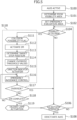
- Figure 5 illustrates a flowchart explaining the flow of control of the EM function according to the present embodiment.
- step S100 automated driving in a single lane by the ALKS is executed (step S100).
- the automated driving controller 10 performs driving controls of the vehicle 1 according to the target path and target speed for the ALKS set by the path generating part 12.
- the path generating part 12 determines, on the basis of the information on a poor visibility area associated with the location information on the vehicle 1 acquired by the environmental condition estimating part 11 and the map information acquired from the map information database 23 as described above, whether a poor visibility area in which the degree of visibility of the road is less than a prescribed value exists on the target path (step S101).
- the EM path-setting part 122 of the path generating part 12 sets an emergency evacuation area in a poor visibility area on the target path on the basis of the vehicle location acquired by the environmental condition estimating part 11 and the map information on the vehicle surroundings acquired from the map information database 23 (step S102). No emergency evacuation area is set in an area with good visibility on the target path.
- the emergency evacuation area is constantly updated while the ALKS is active.
- the environmental condition estimating part 11 determines the possibility or probability of a collision with an obstacle in the vehicle surroundings on the basis of the information on obstacles detected by the external sensor 21 and the vehicle information on the vehicle 1 detected by the internal sensor 22 (step S104).
- the probability of a collision with the obstacle is determined to be high, and control shifts to the EM function to execute the emergency avoidance control (step S 110). If the predicted time to collision TTC with an obstacle is greater than the prescribed value and the probability of a collision is determined to be low, the flow proceeds to step S103. Note that if the possibility of a collision with an obstacle is determined to be high, the environmental condition estimating part 11 also determines whether the obstacle is a stationary object or a moving object.
- step S111 When control shifts to the EM function, a collision possibility flag is raised (step S111) and activation of the EM function, including activation of the autonomous emergency braking for collision avoidance or collision mitigation, is started (step S112).
- the EM path-setting part 122 of the path generating part 12 sets a target stop position according to the activation mode of the EM function and whether the visibility is good or poor (step S113). Specifically, if the reason for activation of the EM function is that there is a stationary object such as a parked vehicle on the target path, that is, if the EM function is activated by the detection of a stationary object, the target stop position is set inside the driving lane of the vehicle 1.
- the target stop position is set inside the driving lane of the vehicle 1.
- the target stop position is set inside the emergency evacuation area set in step S102.
- the EM path-setting part 122 If the target stop position is set inside the driving lane, the EM path-setting part 122 generates a target path to the target stop position on the basis of the location and speed of the vehicle 1 so as to perform an in-lane stop by braking control. On the other hand, if the target stop position is set inside the emergency evacuation area, the EM path-setting part 122 generates a target path to the target stop position on the basis of the location and speed of the vehicle 1 so as to guide the vehicle 1 to a stop by braking control and steering control.
- braking control is performed at the maximum deceleration rate of the system.
- the target stop position is set inside an emergency evacuation area based on the side edge of the road, it is preferable to perform braking control at a deceleration rate for emergency avoidance control that is smaller than the maximum deceleration rate of the system. This is in consideration of the safety of the behavior of the vehicle 1 when stopping the vehicle 1 at the target stop position by steering control and braking control.
- the override threshold values are changed from the normal override threshold values (OEd, OPd, OTd) to override threshold values in accordance with the reason for activation of the EM function (step S 114). Specifically, if the EM function is activated due to the detection of a moving object, the normal override threshold values (OEd, OPd, OTd) are changed to the override threshold values (OEemb, OPemb, OTemb) for the EM activation due to a moving object.
- the normal override threshold values (OEd, OPd, OTd) are changed to the override threshold values (OEema, OPema, OTema) for the EM activation due to a stationary object.
- the automated driving controller 10 activates a direction indicator (not illustrated) in the direction of the target stop position (step S 115).
- the vehicle control part 13 performs a steering avoidance control and a maximum deceleration rate braking control. Accordingly, the vehicle 1 is guided along the target path for EM to the target stop position while decelerating at the maximum deceleration rate (step S 116).
- the automated driving controller 10 is configured to determine whether or not an override is executed due to a control intervention by the driver while the ALKS is active, and the determination as to whether or not an override is executed is continued even after the activation of the EM function (step S1 17). If the engine torque request from the manual control 35 of the accelerator pedal by the driver, the deceleration request from the manual control 36 of the brake pedal, or the steering torque from the manual steering 34 is equal to or greater than the accelerator override threshold value, the brake override threshold value, or the steering override threshold value set in step S 114, the execution of an override is determined and the flow proceeds to step S 106 to deactivate the ALKS. If non-execution of an override is determined, the flow proceeds to step S 118.
- the environmental condition estimating part 11 determines whether the emergency avoidance control is complete on the basis of the vehicle state and the surrounding environment of the vehicle 1 (step S 118). Specifically, if there is no longer an imminent threat of a collision due to an emergency stop or a change in the surrounding environment of the vehicle 1, or if the system is put into an inactive state through the operation of a switch (not illustrated) by the driver, the emergency avoidance control is determined to be complete. In this case, the accelerator override threshold value, brake override threshold value, or steering override threshold value set in step S114 is reset to the normal override threshold value (OEd, OPd, OTd), and the hazard lamps are made to blink (step S119). On the other hand, if the emergency avoidance control is determined to be incomplete, the flow returns to step S116 and the emergency avoidance control is continued.
- OEd, OPd, OTd normal override threshold value
- the environmental condition estimating part 11 determines whether to deactivate the ALKS on the basis of the vehicle state and the surrounding environment of the vehicle 1 (step S106). Specifically, if the execution of an override due to a control intervention by the driver is determined in step S 117 or if the emergency avoidance control is determined to be complete in step S118, or the system is put into an inactive state through the operation of a switch (not illustrated) by the driver, it is determined to deactivate the ALKS system, the ALKS is stopped, and control shifts to the manual driving mode (step S108). On the other hand, if a negative determination is made in step S106, the flow returns to step S104 and the ALKS system remains active.
- a driving control apparatus for a vehicle comprises: an environmental condition estimating part 11 including a surrounding recognition function for recognizing a driving lane of the vehicle, neighboring lanes, other vehicles in each of the lanes, and a surrounding environment, and a function for obtaining a state of movement of the vehicle; a path generating part 12 for generating a target path on the basis of information obtained by the environmental condition estimating part 11; and a vehicle control part 13 configured to perform speed control and steering control for making the vehicle follow the target path.
- the driving control apparatus has an in-lane automated driving (automated lane keeping driving) function that performs in-lane automated driving for maintaining a set speed if no other vehicle is present ahead in the lane of the vehicle and maintaining a set inter-vehicle distance if another vehicle is present ahead, and an EM function that executes an emergency avoidance control, including activation of emergency braking, if a collision with an obstacle present ahead in the lane of the vehicle is predicted.
- in-lane automated driving automated lane keeping driving
- EM function that executes an emergency avoidance control, including activation of emergency braking, if a collision with an obstacle present ahead in the lane of the vehicle is predicted.
- the path generating part 12 has an EM path-setting part (evacuation area setting part) 122 that sets an emergency evacuation area on the target path in case of activation of the EM function on the basis of location information and map information of the vehicle 1 while the in-lane automated driving function is active, and the EM path-setting part 122 is configured to select a target stop position from inside the emergency evacuation area while the EM function is active.
- EM path-setting part evacuation area setting part
- the system is configured to determine an emergency evacuation area after the shift from automated lane keeping driving by the ALKS to the EM function and then, guide the vehicle to a stop in the determined emergency evacuation area, the actual start of evacuation operations will be delayed by the system processing time from the shift to the EM function to the determination of the emergency evacuation area. Accordingly, by setting an emergency evacuation area on the target path in case of activation of the EM function while the automated lane keeping driving function by the ALKS is active, a target stop position can be set inside the emergency evacuation area quickly when the EM is activated.
- the path generating part 12 is configured to determine whether a poor visibility area in which a degree of visibility of the road is less than a prescribed value exists on the target path. If a poor visibility area is determined to exist, the EM path-setting part 122 sets, on the basis of location information and map information of the vehicle, an emergency evacuation area on the target path in case of activation of the EM function.
- the vehicle 1 is traveling through a poor visibility area with poor visibility on the road, there is a possibility that a delay may occur in the detection of the situation ahead in the lane of the vehicle by the system compared to the case of traveling in an area with good visibility. Accordingly, by setting in advance an emergency evacuation area in a poor visibility area on the target path in case of activation of the EM function, the emergency avoidance control can be executed quickly when the EM function is activated. Also, by limiting the setting of the emergency evacuation area to a poor visibility area, it is also possible to reduce the computational load on the automated driving controller 10 compared to the case in which the emergency evacuation area is set constantly.
- the degree of visibility is defined as the visible distance at which an obstacle on the road is visible, and is determined on the basis of road information about the radius of curvature and the vertical grade of the road, and landmarks that exist along the road.
- the prescribed value for determining the degree of visibility is defined as the braking distance required to come to a braking stop without colliding with an obstacle after detecting the obstacle on the target path, and is determined on the basis of road information and speed limit information on the target path.
- the path generating part 12 determines that a poor visibility area exists if the visible distance is less than the braking distance.
- the degree of visibility is determined to be a visible distance based on road information and the existence of a poor visibility area is determined through a comparison with the braking distance required for the vehicle 1 to come to a braking stop without colliding with an obstacle on the basis of road information and speed limit information, the existence of a poor visibility area can be determined objectively in advance, without using information from the external sensor 21 or the like.
- the EM path-setting part 122 sets an emergency evacuation area to include the lateral width of the vehicle 1 with respect to the side edge of the road in the direction of travel of the vehicle 1.
- the emergency evacuation area the narrowest possible area, taking into account the lateral width of the vehicle 1 from the side edge of the road, the vehicle 1 can be stopped in an area on the side edge of the road in the emergency avoidance control. This arrangement makes it possible to lower the risk of collision when the EM function is activated due to the appearance of an oncoming vehicle or the like from the opposite lane, for example.
- the environmental condition estimating part 11 is configured to determine whether the obstacle that causes the EM function to be activated is a stationary object or a moving object, and the EM path-setting part 122 is configured to set a target stop position inside the emergency evacuation area if the obstacle is a moving object, and to set a target stop position inside the driving lane of the vehicle 1 if the obstacle is a stationary object.
- the reason for activation of the EM function is a stationary object such as a parked vehicle on the target path, a target stop position is set inside the driving lane and an in-lane stop is performed by braking control.
- the reason for activation of the EM function is a moving object such as an oncoming vehicle or a pedestrian on the target path, and in particular, if the EM function is activated due to a moving object in a poor visibility area, the vehicle 1 is guided to a stop by braking control and steering control at a target stop position inside an emergency evacuation area set with respect to the side edge of the road.
- emergency avoidance control is executed using not only braking control, but also steering control.
- An emergency avoidance control combining braking control and steering control is also executed in cases such as when a moving object is approaching the vehicle 1. In this way, by changing the target stop position depending on the reason for activation of the EM function, an effective emergency avoidance control corresponding to the EM activation reason or cause can be performed.
- the driving control apparatus for a vehicle further includes an override function that, if there is a control intervention equal to or greater than a prescribed threshold value by the driver while the in-lane automated driving function or the EM function is active, stops the active function and transfers control to the driver, the override function being configured such that a first threshold value is set as the prescribed threshold value while the in-lane automated driving function is active, a second threshold value is set as the prescribed threshold value when the EM function is activated and the obstacle is a stationary object, and a third threshold value is set as the prescribed threshold value when the EM function is activated and the obstacle is a moving object, the third threshold value being greater than the second threshold value, and the second threshold value being greater than the first threshold value.
- the EM function is activated due to the appearance of a moving object such as an oncoming vehicle, for example, while the in-lane automated driving function by the ALKS is active, there is a possibility that the driver will panic and perform excessive driving operations, which may cause an override to be executed unintentionally. If an excessive override operation is executed, there is a possibility of creating a situation in which the vehicle 1 intrudes into the opposite lane or veers off the road.
- the first threshold value as the prescribed threshold value while the in-lane automated driving function is active
- setting the third threshold value greater than the second threshold value when the EM function is activated due to a moving object an excessive override can be suppressed.
- an override by the driver is suppressed more than when the EM function is activated due to a stationary object, and therefore the safety functions of the ALKS can be used to achieve the emergency avoidance control.
- the handover of driving operations is suppressed when the EM is activated during which driving operations are burdensome, the risks arising from the handover of driving operations to the driver can be suppressed.
Landscapes
- Engineering & Computer Science (AREA)
- Automation & Control Theory (AREA)
- Transportation (AREA)
- Mechanical Engineering (AREA)
- Human Computer Interaction (AREA)
- Traffic Control Systems (AREA)
- Control Of Driving Devices And Active Controlling Of Vehicle (AREA)
Applications Claiming Priority (1)
| Application Number | Priority Date | Filing Date | Title |
|---|---|---|---|
| JP2022191846A JP2024079110A (ja) | 2022-11-30 | 2022-11-30 | 車両の走行制御装置 |
Publications (2)
| Publication Number | Publication Date |
|---|---|
| EP4378779A1 true EP4378779A1 (de) | 2024-06-05 |
| EP4378779B1 EP4378779B1 (de) | 2025-04-16 |
Family
ID=88511515
Family Applications (1)
| Application Number | Title | Priority Date | Filing Date |
|---|---|---|---|
| EP23205655.6A Active EP4378779B1 (de) | 2022-11-30 | 2023-10-24 | Antriebssteuerungsvorrichtung für ein fahrzeug |
Country Status (3)
| Country | Link |
|---|---|
| EP (1) | EP4378779B1 (de) |
| JP (1) | JP2024079110A (de) |
| HU (1) | HUE071350T2 (de) |
Cited By (1)
| Publication number | Priority date | Publication date | Assignee | Title |
|---|---|---|---|---|
| US12434694B2 (en) * | 2022-08-31 | 2025-10-07 | Toyota Jidosha Kabushiki Kaisha | Driving support device, driving support method, and driving support program |
Citations (6)
| Publication number | Priority date | Publication date | Assignee | Title |
|---|---|---|---|---|
| US20190202472A1 (en) * | 2017-12-28 | 2019-07-04 | Hyundai Motor Company | Apparatus and method for automatically controlling driving assist function of vehicle |
| US20200307646A1 (en) * | 2019-03-29 | 2020-10-01 | Honda Motor Co., Ltd. | Vehicle control system |
| EP3974277A1 (de) * | 2020-09-24 | 2022-03-30 | Suzuki Motor Corporation | Antriebssteuerungsvorrichtung für fahrzeug |
| JP2022060076A (ja) | 2020-10-02 | 2022-04-14 | 株式会社Subaru | 車両の走行制御装置 |
| JP2022091517A (ja) | 2020-12-09 | 2022-06-21 | トヨタ自動車株式会社 | 車両制御システム及び自動運転車両並びに車両制御方法 |
| EP4052982A1 (de) * | 2021-03-03 | 2022-09-07 | Suzuki Motor Corporation | Antriebssteuerungsvorrichtung für fahrzeug |
Family Cites Families (5)
| Publication number | Priority date | Publication date | Assignee | Title |
|---|---|---|---|---|
| JPH10124799A (ja) * | 1996-10-16 | 1998-05-15 | Toyota Motor Corp | 車両用走行安全検知装置及び車両用走行制御装置 |
| US10832061B2 (en) * | 2016-07-22 | 2020-11-10 | Hitachi Automotive Systems, Ltd. | Traveling road boundary estimation apparatus and traveling assistance system using same |
| KR20200081530A (ko) * | 2018-12-19 | 2020-07-08 | 주식회사 만도 | 자율 주행 차량의 안전 제어 시스템 및 방법 |
| JP7648423B2 (ja) * | 2021-03-31 | 2025-03-18 | 本田技研工業株式会社 | 車両制御装置及び車両、並びに、車両制御装置の制御方法及びプログラム |
| CN115402305B (zh) * | 2022-11-01 | 2023-02-03 | 中国第一汽车股份有限公司 | 扭矩补偿方法、装置、存储介质及电子装置 |
-
2022
- 2022-11-30 JP JP2022191846A patent/JP2024079110A/ja active Pending
-
2023
- 2023-10-24 HU HUE23205655A patent/HUE071350T2/hu unknown
- 2023-10-24 EP EP23205655.6A patent/EP4378779B1/de active Active
Patent Citations (6)
| Publication number | Priority date | Publication date | Assignee | Title |
|---|---|---|---|---|
| US20190202472A1 (en) * | 2017-12-28 | 2019-07-04 | Hyundai Motor Company | Apparatus and method for automatically controlling driving assist function of vehicle |
| US20200307646A1 (en) * | 2019-03-29 | 2020-10-01 | Honda Motor Co., Ltd. | Vehicle control system |
| EP3974277A1 (de) * | 2020-09-24 | 2022-03-30 | Suzuki Motor Corporation | Antriebssteuerungsvorrichtung für fahrzeug |
| JP2022060076A (ja) | 2020-10-02 | 2022-04-14 | 株式会社Subaru | 車両の走行制御装置 |
| JP2022091517A (ja) | 2020-12-09 | 2022-06-21 | トヨタ自動車株式会社 | 車両制御システム及び自動運転車両並びに車両制御方法 |
| EP4052982A1 (de) * | 2021-03-03 | 2022-09-07 | Suzuki Motor Corporation | Antriebssteuerungsvorrichtung für fahrzeug |
Cited By (1)
| Publication number | Priority date | Publication date | Assignee | Title |
|---|---|---|---|---|
| US12434694B2 (en) * | 2022-08-31 | 2025-10-07 | Toyota Jidosha Kabushiki Kaisha | Driving support device, driving support method, and driving support program |
Also Published As
| Publication number | Publication date |
|---|---|
| JP2024079110A (ja) | 2024-06-11 |
| EP4378779B1 (de) | 2025-04-16 |
| HUE071350T2 (hu) | 2025-08-28 |
Similar Documents
| Publication | Publication Date | Title |
|---|---|---|
| US11897488B2 (en) | Autonomous driving assistance method and device | |
| EP4052982B1 (de) | Antriebssteuerungsvorrichtung für fahrzeug | |
| JP7189509B2 (ja) | 車両の走行制御装置 | |
| EP4378780A1 (de) | Antriebssteuerungsvorrichtung für ein fahrzeug | |
| US11186275B2 (en) | Vehicle control system | |
| US20190227546A1 (en) | Driving Control Apparatus For Vehicle | |
| US20230234574A1 (en) | Vehicle driving assist device | |
| US11938924B2 (en) | Driving assistance control apparatus for vehicle, driving assistance control system for vehicle, and driving assistance control method for vehicle | |
| US20210394752A1 (en) | Traveling Control Device, Vehicle, and Traveling Control Method | |
| US20110313665A1 (en) | Method for Automatically Detecting a Driving Maneuver of a Motor Vehicle and a Driver Assistance System Comprising Said Method | |
| US12233863B2 (en) | Vehicle driving assist device | |
| JP2020144789A (ja) | 車両の走行制御装置 | |
| US10994726B2 (en) | Vehicle control system | |
| JP7813171B2 (ja) | 車両の運転支援装置、及び、車両の運転支援システム | |
| EP4155152B1 (de) | Antriebssteuerungsvorrichtung für fahrzeug | |
| EP4378778B1 (de) | Fahrsteuerungsvorrichtung für ein fahrzeug | |
| US20220314977A1 (en) | Vehicle control device, vehicle, method of controlling vehicle control device, and non-transitory computer-readable storage medium | |
| JP7813145B2 (ja) | 車両の運転支援装置 | |
| EP3974277B1 (de) | Antriebssteuerungsvorrichtung für fahrzeug | |
| EP4155149B1 (de) | Steuerungsvorrichtung für fahrzeug | |
| US12304468B2 (en) | Vehicle driving assist device | |
| EP3974293B1 (de) | Antriebssteuerungsvorrichtung für fahrzeug | |
| EP4378779B1 (de) | Antriebssteuerungsvorrichtung für ein fahrzeug | |
| US20240404403A1 (en) | Vehicle control system and vehicle control method | |
| EP4600102A1 (de) | Antriebssteuerungsvorrichtung für ein fahrzeug |
Legal Events
| Date | Code | Title | Description |
|---|---|---|---|
| PUAI | Public reference made under article 153(3) epc to a published international application that has entered the european phase |
Free format text: ORIGINAL CODE: 0009012 |
|
| STAA | Information on the status of an ep patent application or granted ep patent |
Free format text: STATUS: REQUEST FOR EXAMINATION WAS MADE |
|
| 17P | Request for examination filed |
Effective date: 20231024 |
|
| AK | Designated contracting states |
Kind code of ref document: A1 Designated state(s): AL AT BE BG CH CY CZ DE DK EE ES FI FR GB GR HR HU IE IS IT LI LT LU LV MC ME MK MT NL NO PL PT RO RS SE SI SK SM TR |
|
| GRAP | Despatch of communication of intention to grant a patent |
Free format text: ORIGINAL CODE: EPIDOSNIGR1 |
|
| STAA | Information on the status of an ep patent application or granted ep patent |
Free format text: STATUS: GRANT OF PATENT IS INTENDED |
|
| INTG | Intention to grant announced |
Effective date: 20250114 |
|
| GRAS | Grant fee paid |
Free format text: ORIGINAL CODE: EPIDOSNIGR3 |
|
| GRAA | (expected) grant |
Free format text: ORIGINAL CODE: 0009210 |
|
| STAA | Information on the status of an ep patent application or granted ep patent |
Free format text: STATUS: THE PATENT HAS BEEN GRANTED |
|
| AK | Designated contracting states |
Kind code of ref document: B1 Designated state(s): AL AT BE BG CH CY CZ DE DK EE ES FI FR GB GR HR HU IE IS IT LI LT LU LV MC ME MK MT NL NO PL PT RO RS SE SI SK SM TR |
|
| REG | Reference to a national code |
Ref country code: GB Ref legal event code: FG4D |
|
| REG | Reference to a national code |
Ref country code: CH Ref legal event code: EP |
|
| REG | Reference to a national code |
Ref country code: IE Ref legal event code: FG4D |
|
| REG | Reference to a national code |
Ref country code: DE Ref legal event code: R096 Ref document number: 602023002956 Country of ref document: DE |
|
| REG | Reference to a national code |
Ref country code: NL Ref legal event code: MP Effective date: 20250416 |
|
| REG | Reference to a national code |
Ref country code: HU Ref legal event code: AG4A Ref document number: E071350 Country of ref document: HU |
|
| PG25 | Lapsed in a contracting state [announced via postgrant information from national office to epo] |
Ref country code: NL Free format text: LAPSE BECAUSE OF FAILURE TO SUBMIT A TRANSLATION OF THE DESCRIPTION OR TO PAY THE FEE WITHIN THE PRESCRIBED TIME-LIMIT Effective date: 20250416 |
|
| REG | Reference to a national code |
Ref country code: AT Ref legal event code: MK05 Ref document number: 1785424 Country of ref document: AT Kind code of ref document: T Effective date: 20250416 |
|
| PG25 | Lapsed in a contracting state [announced via postgrant information from national office to epo] |
Ref country code: PT Free format text: LAPSE BECAUSE OF FAILURE TO SUBMIT A TRANSLATION OF THE DESCRIPTION OR TO PAY THE FEE WITHIN THE PRESCRIBED TIME-LIMIT Effective date: 20250818 Ref country code: FI Free format text: LAPSE BECAUSE OF FAILURE TO SUBMIT A TRANSLATION OF THE DESCRIPTION OR TO PAY THE FEE WITHIN THE PRESCRIBED TIME-LIMIT Effective date: 20250416 Ref country code: ES Free format text: LAPSE BECAUSE OF FAILURE TO SUBMIT A TRANSLATION OF THE DESCRIPTION OR TO PAY THE FEE WITHIN THE PRESCRIBED TIME-LIMIT Effective date: 20250416 |
|
| REG | Reference to a national code |
Ref country code: LT Ref legal event code: MG9D |
|
| PG25 | Lapsed in a contracting state [announced via postgrant information from national office to epo] |
Ref country code: NO Free format text: LAPSE BECAUSE OF FAILURE TO SUBMIT A TRANSLATION OF THE DESCRIPTION OR TO PAY THE FEE WITHIN THE PRESCRIBED TIME-LIMIT Effective date: 20250716 Ref country code: GR Free format text: LAPSE BECAUSE OF FAILURE TO SUBMIT A TRANSLATION OF THE DESCRIPTION OR TO PAY THE FEE WITHIN THE PRESCRIBED TIME-LIMIT Effective date: 20250717 |
|
| PG25 | Lapsed in a contracting state [announced via postgrant information from national office to epo] |
Ref country code: PL Free format text: LAPSE BECAUSE OF FAILURE TO SUBMIT A TRANSLATION OF THE DESCRIPTION OR TO PAY THE FEE WITHIN THE PRESCRIBED TIME-LIMIT Effective date: 20250416 |
|
| PG25 | Lapsed in a contracting state [announced via postgrant information from national office to epo] |
Ref country code: BG Free format text: LAPSE BECAUSE OF FAILURE TO SUBMIT A TRANSLATION OF THE DESCRIPTION OR TO PAY THE FEE WITHIN THE PRESCRIBED TIME-LIMIT Effective date: 20250416 |
|
| PG25 | Lapsed in a contracting state [announced via postgrant information from national office to epo] |
Ref country code: HR Free format text: LAPSE BECAUSE OF FAILURE TO SUBMIT A TRANSLATION OF THE DESCRIPTION OR TO PAY THE FEE WITHIN THE PRESCRIBED TIME-LIMIT Effective date: 20250416 |
|
| PG25 | Lapsed in a contracting state [announced via postgrant information from national office to epo] |
Ref country code: AT Free format text: LAPSE BECAUSE OF FAILURE TO SUBMIT A TRANSLATION OF THE DESCRIPTION OR TO PAY THE FEE WITHIN THE PRESCRIBED TIME-LIMIT Effective date: 20250416 |
|
| PGFP | Annual fee paid to national office [announced via postgrant information from national office to epo] |
Ref country code: FR Payment date: 20250908 Year of fee payment: 3 |
|
| PG25 | Lapsed in a contracting state [announced via postgrant information from national office to epo] |
Ref country code: RS Free format text: LAPSE BECAUSE OF FAILURE TO SUBMIT A TRANSLATION OF THE DESCRIPTION OR TO PAY THE FEE WITHIN THE PRESCRIBED TIME-LIMIT Effective date: 20250716 |
|
| PG25 | Lapsed in a contracting state [announced via postgrant information from national office to epo] |
Ref country code: IS Free format text: LAPSE BECAUSE OF FAILURE TO SUBMIT A TRANSLATION OF THE DESCRIPTION OR TO PAY THE FEE WITHIN THE PRESCRIBED TIME-LIMIT Effective date: 20250816 |
|
| PG25 | Lapsed in a contracting state [announced via postgrant information from national office to epo] |
Ref country code: LV Free format text: LAPSE BECAUSE OF FAILURE TO SUBMIT A TRANSLATION OF THE DESCRIPTION OR TO PAY THE FEE WITHIN THE PRESCRIBED TIME-LIMIT Effective date: 20250416 |
|
| PGFP | Annual fee paid to national office [announced via postgrant information from national office to epo] |
Ref country code: HU Payment date: 20250929 Year of fee payment: 3 |
|
| PGFP | Annual fee paid to national office [announced via postgrant information from national office to epo] |
Ref country code: DE Payment date: 20250902 Year of fee payment: 3 |
|
| PG25 | Lapsed in a contracting state [announced via postgrant information from national office to epo] |
Ref country code: SM Free format text: LAPSE BECAUSE OF FAILURE TO SUBMIT A TRANSLATION OF THE DESCRIPTION OR TO PAY THE FEE WITHIN THE PRESCRIBED TIME-LIMIT Effective date: 20250416 Ref country code: DK Free format text: LAPSE BECAUSE OF FAILURE TO SUBMIT A TRANSLATION OF THE DESCRIPTION OR TO PAY THE FEE WITHIN THE PRESCRIBED TIME-LIMIT Effective date: 20250416 |
|
| REG | Reference to a national code |
Ref country code: DE Ref legal event code: R097 Ref document number: 602023002956 Country of ref document: DE |
|
| PG25 | Lapsed in a contracting state [announced via postgrant information from national office to epo] |
Ref country code: CZ Free format text: LAPSE BECAUSE OF FAILURE TO SUBMIT A TRANSLATION OF THE DESCRIPTION OR TO PAY THE FEE WITHIN THE PRESCRIBED TIME-LIMIT Effective date: 20250416 |
|
| PG25 | Lapsed in a contracting state [announced via postgrant information from national office to epo] |
Ref country code: EE Free format text: LAPSE BECAUSE OF FAILURE TO SUBMIT A TRANSLATION OF THE DESCRIPTION OR TO PAY THE FEE WITHIN THE PRESCRIBED TIME-LIMIT Effective date: 20250416 |
|
| PG25 | Lapsed in a contracting state [announced via postgrant information from national office to epo] |
Ref country code: SK Free format text: LAPSE BECAUSE OF FAILURE TO SUBMIT A TRANSLATION OF THE DESCRIPTION OR TO PAY THE FEE WITHIN THE PRESCRIBED TIME-LIMIT Effective date: 20250416 |
|
| PG25 | Lapsed in a contracting state [announced via postgrant information from national office to epo] |
Ref country code: IT Free format text: LAPSE BECAUSE OF FAILURE TO SUBMIT A TRANSLATION OF THE DESCRIPTION OR TO PAY THE FEE WITHIN THE PRESCRIBED TIME-LIMIT Effective date: 20250416 |
|
| PLBE | No opposition filed within time limit |
Free format text: ORIGINAL CODE: 0009261 |
|
| STAA | Information on the status of an ep patent application or granted ep patent |
Free format text: STATUS: NO OPPOSITION FILED WITHIN TIME LIMIT |
|
| REG | Reference to a national code |
Ref country code: CH Ref legal event code: L10 Free format text: ST27 STATUS EVENT CODE: U-0-0-L10-L00 (AS PROVIDED BY THE NATIONAL OFFICE) Effective date: 20260225 |
|
| PG25 | Lapsed in a contracting state [announced via postgrant information from national office to epo] |
Ref country code: RO Free format text: LAPSE BECAUSE OF FAILURE TO SUBMIT A TRANSLATION OF THE DESCRIPTION OR TO PAY THE FEE WITHIN THE PRESCRIBED TIME-LIMIT Effective date: 20250416 |
|
| 26N | No opposition filed |
Effective date: 20260119 |