EP4384253B1 - Übergossene ballonbefestigung an einem schaft - Google Patents
Übergossene ballonbefestigung an einem schaft Download PDFInfo
- Publication number
- EP4384253B1 EP4384253B1 EP22777031.0A EP22777031A EP4384253B1 EP 4384253 B1 EP4384253 B1 EP 4384253B1 EP 22777031 A EP22777031 A EP 22777031A EP 4384253 B1 EP4384253 B1 EP 4384253B1
- Authority
- EP
- European Patent Office
- Prior art keywords
- balloon
- shut
- catheter shaft
- overmold
- shaft
- Prior art date
- Legal status (The legal status is an assumption and is not a legal conclusion. Google has not performed a legal analysis and makes no representation as to the accuracy of the status listed.)
- Active
Links
Images



Classifications
-
- A—HUMAN NECESSITIES
- A61—MEDICAL OR VETERINARY SCIENCE; HYGIENE
- A61M—DEVICES FOR INTRODUCING MEDIA INTO, OR ONTO, THE BODY; DEVICES FOR TRANSDUCING BODY MEDIA OR FOR TAKING MEDIA FROM THE BODY; DEVICES FOR PRODUCING OR ENDING SLEEP OR STUPOR
- A61M25/00—Catheters; Hollow probes
- A61M25/10—Balloon catheters
- A61M25/1027—Making of balloon catheters
- A61M25/1034—Joining of shaft and balloon
-
- A—HUMAN NECESSITIES
- A61—MEDICAL OR VETERINARY SCIENCE; HYGIENE
- A61M—DEVICES FOR INTRODUCING MEDIA INTO, OR ONTO, THE BODY; DEVICES FOR TRANSDUCING BODY MEDIA OR FOR TAKING MEDIA FROM THE BODY; DEVICES FOR PRODUCING OR ENDING SLEEP OR STUPOR
- A61M25/00—Catheters; Hollow probes
- A61M25/10—Balloon catheters
- A61M25/1027—Making of balloon catheters
- A61M25/1029—Production methods of the balloon members, e.g. blow-moulding, extruding, deposition or by wrapping a plurality of layers of balloon material around a mandril
-
- A—HUMAN NECESSITIES
- A61—MEDICAL OR VETERINARY SCIENCE; HYGIENE
- A61M—DEVICES FOR INTRODUCING MEDIA INTO, OR ONTO, THE BODY; DEVICES FOR TRANSDUCING BODY MEDIA OR FOR TAKING MEDIA FROM THE BODY; DEVICES FOR PRODUCING OR ENDING SLEEP OR STUPOR
- A61M25/00—Catheters; Hollow probes
- A61M25/10—Balloon catheters
- A61M25/1027—Making of balloon catheters
- A61M25/1036—Making parts for balloon catheter systems, e.g. shafts or distal ends
-
- B—PERFORMING OPERATIONS; TRANSPORTING
- B29—WORKING OF PLASTICS; WORKING OF SUBSTANCES IN A PLASTIC STATE IN GENERAL
- B29C—SHAPING OR JOINING OF PLASTICS; SHAPING OF MATERIAL IN A PLASTIC STATE, NOT OTHERWISE PROVIDED FOR; AFTER-TREATMENT OF THE SHAPED PRODUCTS, e.g. REPAIRING
- B29C45/00—Injection moulding, i.e. forcing the required volume of moulding material through a nozzle into a closed mould; Apparatus therefor
- B29C45/14—Injection moulding, i.e. forcing the required volume of moulding material through a nozzle into a closed mould; Apparatus therefor incorporating preformed parts or layers, e.g. injection moulding around inserts or for coating articles
- B29C45/14467—Joining articles or parts of a single article
-
- A—HUMAN NECESSITIES
- A61—MEDICAL OR VETERINARY SCIENCE; HYGIENE
- A61M—DEVICES FOR INTRODUCING MEDIA INTO, OR ONTO, THE BODY; DEVICES FOR TRANSDUCING BODY MEDIA OR FOR TAKING MEDIA FROM THE BODY; DEVICES FOR PRODUCING OR ENDING SLEEP OR STUPOR
- A61M25/00—Catheters; Hollow probes
- A61M25/10—Balloon catheters
- A61M2025/1043—Balloon catheters with special features or adapted for special applications
- A61M2025/1052—Balloon catheters with special features or adapted for special applications for temporarily occluding a vessel for isolating a sector
-
- A—HUMAN NECESSITIES
- A61—MEDICAL OR VETERINARY SCIENCE; HYGIENE
- A61M—DEVICES FOR INTRODUCING MEDIA INTO, OR ONTO, THE BODY; DEVICES FOR TRANSDUCING BODY MEDIA OR FOR TAKING MEDIA FROM THE BODY; DEVICES FOR PRODUCING OR ENDING SLEEP OR STUPOR
- A61M2207/00—Methods of manufacture, assembly or production
-
- B—PERFORMING OPERATIONS; TRANSPORTING
- B29—WORKING OF PLASTICS; WORKING OF SUBSTANCES IN A PLASTIC STATE IN GENERAL
- B29K—INDEXING SCHEME ASSOCIATED WITH SUBCLASSES B29B, B29C OR B29D, RELATING TO MOULDING MATERIALS OR TO MATERIALS FOR MOULDS, REINFORCEMENTS, FILLERS OR PREFORMED PARTS, e.g. INSERTS
- B29K2683/00—Use of polymers having silicon, with or without sulfur, nitrogen, oxygen or carbon only, in the main chain, for preformed parts, e.g. for inserts
-
- B—PERFORMING OPERATIONS; TRANSPORTING
- B29—WORKING OF PLASTICS; WORKING OF SUBSTANCES IN A PLASTIC STATE IN GENERAL
- B29L—INDEXING SCHEME ASSOCIATED WITH SUBCLASS B29C, RELATING TO PARTICULAR ARTICLES
- B29L2031/00—Other particular articles
- B29L2031/753—Medical equipment; Accessories therefor
- B29L2031/7542—Catheters
- B29L2031/7543—Balloon catheters
Definitions
- This disclosure relates to attachment of a balloon to a shaft via overmolding.
- an inflatable balloon attached to shaft may be inserted into the body and inflated to control fluid flow.
- the balloon may be inflated to pressures at which weak and/or defective balloons may burst or become detached from the shaft.
- such a failure event may lead to harm to the individual undergoing the procedure and/or require repeat of various portions of the procedure. Accordingly, technologies that decrease the likelihood of failures and/or increase the operational tolerances of such inflatable balloon devices will drive demand for these devices.
- US 2017/0100570 describes a cage that can be positioned around a medical balloon, such as an angioplasty balloon, to assist in a medical procedure.
- the cage can include a plurality of strips, each extending between a set of rings including first and second rings. As the balloon expands, the first and second rings move closer together and allow the strips to expand outward.
- the cage may have wedge dissectors on the strips.
- US 2019/0142246 describes a visualization catheter that includes an elongate shaft, a cap portion, and an offset balloon coupled to the distal end of the shaft.
- the elongate shaft includes a proximal end, a distal end, and a central axis defined therebetween.
- the cap portion is coupled to the distal end of the shaft.
- the cap portion also includes a visualization element and defines an aperture.
- the offset balloon is coupled to the distal end of the shaft and encapsulates the cap portion.
- the offset balloon defines a center point offset relative to the central axis of the shaft.
- US 2019/0030282 describes methods for predicting the risk of recurrence and/or metastasis in primary cutaneous squamous cell carcinoma.
- JP 2002-143311 describes a balloon catheter wherein both ends of the balloon are fixed onto an outer surface near a point of the flexible shaft by the fixing means, the fixing strength of the basic end-side fixing part of the balloon is weaker than that of the point-side fixing part in fixing the both ends of the balloon.
- an inflatable balloon may be attached to a shaft to form an inflatable device.
- the shaft may include a catheter and/or lumen.
- the inflatable device may be inserted into the body and inflated to control fluid flow surrounding the inflatable device.
- the balloon may be attached to the shaft, for example, using an adhesive and/or via overmolding.
- the conventional wisdom is to attach the balloon without pre-defined shaping of the attachment medium, allowing flow and/or expansion of the attachment medium to an equilibrium state.
- the devices and fabrication techniques disclosed herein are formed with and/or use a shut-off that constrains the flow and/or expansion of the attachment medium during overmolding, which may restrict the attachment surface area.
- the resultant overmold extends from the balloon to a shut-off ridge.
- the shut-off ridge may include a defined shape formed through the constrained shaping provided by the shut-off during overmolding.
- the overmold with the shut-off ridge does not undergo unconstrained expansion and does not include bubbles.
- the resultant overmold without bubbles has a higher burst strength to similarly sized attachments made with adhesives, which can form bubbles due to expansion.
- the shaping of the shut-off ridges prevents flash on the ends of the overmold. In the medical context, flash can injure tissue during a medical procedure, which can lead to dangerous conditions such as thrombosis.
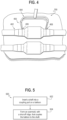
- Figure 1 shows a cross-sectional view of an example inflatable device 100 including a balloon 110 attached to a shaft 120 via an overmold 130.
- the balloon 110 encircles the shaft 120.
- the outer face of the overmold 130 extends from an end 112 of the balloon 110 to a shut-off ridge 132.
- the shut-off ridge 132 includes a tapered shaping. In some cases, the shut-off ridge may cover only a part of the outer face of the overmold. In some cases, the shut-off ridge may cover the entire outer face of the overmold.
- the shut-off ridge 132 encircles the shaft 120 in an annular shape.
- the overmold 130 may meet the end of the balloon to form a flush joint. In other words, the outer surfaces of the balloon and overmold may be aligned to prevent and/or minimize discontinuity between the end of the balloon and the start of the outer surface of the taper.
- the tapered shape of the shut-off ridge 132 may be free of discontinuities (or other roughness such as flash) where the shut-off ridge 132 tapers into the shaft. As discussed above, discontinuities and/or other roughness/flash may cause tissue damage during use of the balloon and shaft device in a medical context.
- the overmold 130 may include extension 131 under the balloon 110 via the inner surfaces of the overmold.
- the shaft includes an opening 122 that places the shaft in fluid (e.g., gas and/or liquid) contact or communication with the balloon. Accordingly, fluid may be sent through the shaft to increase the pressure inside the shaft 120. Via the opening 122, the pressure is transferred to the balloon, and the balloon 110 may inflate.
- fluid e.g., gas and/or liquid
- the shaft may be made from various materials such as polymeric materials, for example, silicone, polyvinyls, polyethlyenes, polyurethane, polyurethane co-polymers, polyvinyl chloride (PVC), and/or other polymers.
- the balloon may be made out of polymeric materials, for example, silicone, silicone derivatives, or certain polyurethanes with high modulus of elasticity.
- the balloon may be made out of polyethylene terephthalate (PET) or nylon.
- PET polyethylene terephthalate
- the shaft may be more rigid than the balloon.
- a silicone balloon is paired with a silicone shaft, in order to improve adhesion between the balloon and the shaft.
- a polyurethane balloon is paired with a shaft made of polyurethane, polyurethane co-polymers, or PVC, in order improve adhesion between the balloon and the shaft.
- the balloon is a conforming balloon, intended to expand or stretch in response to a volume of fluid injected into the balloon, to thereby fill the cross-section of a vessel or lumen in which the balloon is inserted, without causing tissue damage from high forces or pressure exerted on the walls of the vessel or lumen.
- the balloon may be pre-formed to have a defined shape when inflated.
- a retrograde coronary sinus perfusion catheter may include a pre-formed bell-shaped balloon.
- the overmold may be formed using the material of the balloon and/or the shaft. Some materials, such as silicone and/or other self-adhering materials may form physically secure bonds when placed in contact with components made using that same material.
- the balloon includes two coupling ports 114 at the ends of the balloon 110.
- the shaft 120 is inserted through the two coupling ports and the overmolds 130 attach the balloon to the shaft.
- the balloon may have other numbers of coupling ports.
- a balloon with a single coupling port may be affixed to the distal end of a shaft.
- a balloon with three coupling ports may be used at a shaft y-type junction.
- Caps (which may also be attached via overmolding) may be applied to coupling ports without an inserted shaft. Accordingly, a balloon with more coupling ports than used for shaft insertion may still be implemented.
- the inner surface of the coupling ports 114 may be in contact with the outer surface of the shaft 120.
- the inner surface of the coupling ports 114 may include ribs 115.
- the ribs 115 may encircle the shaft and may have an annular shape.
- the ribs 115 may increase contact pressure with the shaft surface 120.
- the ribs 115 may increase blockage of material, for example, from escaping the balloon 110 via the coupling port 114.
- the example inflatable device 100 may be used in various medical contexts where an inflatable device with a conforming balloon is used to control fluid flow.
- the device may be inserted into the body an inflated to constrict blood flow in an artery, such as the uterine artery.
- the device may be used in other procedures to implement balloon occlusion, support of stent insertion, and/or other medical balloon inflation procedures.
- Figure 2 shows an alternate solid view of the example inflatable device 100 including the including the balloon attached to the shaft 120 via the overmold 130.
- Figure 3 shows an example mold 200.
- the example mold 200 may include a shaft cavity 220 sized to accept a shaft 120.
- the example mold 200 may include a balloon cavity 210 sized to accept a balloon 110 when an end of the shaft 120 is inserted into a coupling port 114 on the balloon 110. Accordingly, the mold may operate when a balloon and shaft are both inserted into their respective cavities 210, 220.
- the balloon cavity 210 may include a port wall that may be sized and shaped to secure the coupling port 114 of the balloon during molding.
- the example mold 200 may include an overmolding cavity 230.
- the example mold 200 may include a material channel 240 configured to receive an overmolding medium.
- the material channel 240 may receive the material from an injection channel 242 and deliver the material (e.g., for formation of the overmold 130) to the overmolding cavity 230.
- the injection channel 242 may extend from the exterior of the mold to the material channel 240 to allow material to be supplied to the mold during molding.
- the example mold 200 may include an inner shut-off 250 and an outer shut-off 260 spaced farther from the balloon than the inner shut-off 250.
- the inner shut-off 250 and/or the outer shut-off 260 may comprise an annular structure that surrounds the shaft 120, or the shaft 120 and the balloon 110.
- the annular structure may comprise at least two pieces, for example, one piece being positioned in mold portion 298, and the other piece being position in mold portion 299, such that when mold portions 298 and 299 are closed together, the inner shut-off 250 and/or the outer shut-off 260 compress and seal around the shaft 120, or the shaft 120 and the balloon 110.
- the inner shut-off 250 and/or the outer shut-off 260 may be constructed of a heat resistance polyamide, such as, for example, TORLON ® .
- the overmolding cavity 230 may be situated between the inner 250 and outer shut-offs 260.
- the inner 250 and outer shut-offs 260 may work to shape the end of the overmold.
- the outer shut-off 260 (in concert with the walls of the overmolding cavity 230) shapes the resulting overmold to create a taper-shaped shut-off ridge (e.g., without flash or other roughness).
- the inner shut-off 250 may be positioned and sized to create a flush joint between the overmold and the outer surface of the coupling port 114 of the balloon 110.
- the flush joint may be ensured by setting the inner surface of the inner shut-off 250 to be flush with the port wall of the balloon cavity 210.
- the inner shut-off 250 may secure the coupling port 114 of the balloon 110 and perform the function of the port wall. In some cases, using a single part for both the port wall and inner shut-off 250 may help ensure a flush joint for the overmold 130.
- the overmolding cavity, the material channel, and/or the injection channel may be filled (or partially filled) with the molding material.
- the molding material may include the material of the balloon and/or shaft.
- the material may be silicone.
- the material may be allowed to cure and/or a curing processing may be affirmatively applied.
- the mold may be raised to a reaction temperature at which silicone will cure after exposure.
- the reaction temperature may include a melting temperature for a material or other temperature at which one or more physical properties of the material may change.
- the molded inflatable device 402 may be removed from the mold 200.
- a channel form 404 may form attached to the molded inflatable device 402.
- the channel form 404 may have one or more attachment points at the overmolds 406 on the inflatable device 402.
- the channel form 404 may be removed from the inflatable device 402, for example, by cutting, ablation, pulling, or other removal. In some cases, the removal may result in a smooth surface with continuity with the surrounding surface of the overmold 406.
- the removal may result in a cut-point (or other removal technique) artifact on the surface of the overmold 406 at the location of the removal of the channel form.
- the artifact may include a visible discontinuity, a surface quality discontinuity, and/or other discontinuity with the surrounding overmold surface.
- the example mold 200 may include multiple complementary parts that may be opened and/or disassembled to allow for loading of the mold (e.g., with the balloon and the shaft) prior to molding.
- the mold may include two complementary portions 298, 299 that may close together to hold the balloon and shaft relative to one another and the shut-offs during molding.
- the shut-offs may be replaceable to allow modification of the shape/size of the shut-off ridge and/or the shape of the end of the overmold 130 abutting the coupling port 114 of the balloon 110.
- Figure 5 shows an example method 500 for fabricating an inflatable device.
- the device may be fabricated by inserting a shaft into a coupling port on a balloon (502). Then, forming an overmold, with a shut-off ridge, that couples the balloon to the shaft (504) works to join the two components.
- the example method 500 may be expanded and/or altered to support fabrication of an inflatable device with any of or any combination of the features discussed above. Further, the example method 500 may performed using the example mold 200 (or other appropriately designed mold). In some cases, a resultant product may be specified as being a result of implementing the example method 500.
- Figure 6 shows a detail view of example shut-offs 610, 620.
- the detail view shows internal structure of the example shut-offs 610, 620.
- the example inner shut-off 610 is positioned/sized to create a flush joint 612 where the balloon 611 abuts the overmold 630.
- the outer shut-off 620 is positioned/shaped to create a shut-off ridge flush with the shaft at the end of the overmold 630 away from the balloon 611. Other overmold shapes are possible.
- Figure 7 shows an example of a completed inflation device 700 that includes a balloon 710, a shaft 720, and overmolds 730.
- the example inflation device 700 has flush joints 732 created by an inner shut off and tapered shut-off ridges 734 shaped by an outer shut-off.
Landscapes
- Health & Medical Sciences (AREA)
- Heart & Thoracic Surgery (AREA)
- Life Sciences & Earth Sciences (AREA)
- Engineering & Computer Science (AREA)
- Pulmonology (AREA)
- Public Health (AREA)
- Veterinary Medicine (AREA)
- Biophysics (AREA)
- Child & Adolescent Psychology (AREA)
- Anesthesiology (AREA)
- Biomedical Technology (AREA)
- Hematology (AREA)
- Animal Behavior & Ethology (AREA)
- General Health & Medical Sciences (AREA)
- Manufacturing & Machinery (AREA)
- Mechanical Engineering (AREA)
- Media Introduction/Drainage Providing Device (AREA)
- Toys (AREA)
- Casting Or Compression Moulding Of Plastics Or The Like (AREA)
Claims (16)
- Vorrichtung (100), Folgendes umfassend:einen Katheterschaft (120);einen Ballon (110) in Druckverbindung mit dem Katheterschaft (120); undeinen ersten Überguss (130), der den Ballon (110) mit dem Katheterschaft verbindet, wobei sich der erste Überguss (130) von dem Ballon (110) zu einem Verschlusskamm (132) erstreckt.
- Vorrichtung nach einem der vorhergehenden Ansprüche, wobei der Verschlusskamm eine ringförmige Gestalt um den Katheterschaft (120) herum ausbildet.
- Vorrichtung nach einem der vorhergehenden Ansprüche, wobei der erste Überguss (130) unter Verwendung eines Materials ausgebildet ist, das mit einem Material des Ballons (110) identisch ist, wobei das Material gegebenenfalls Silikon ist.
- Vorrichtung nach einem der Ansprüche 1 bis 3, wobei der Ballon (110) einen ersten Verbindungsport (114) umfasst, der den Katheterschaft (120) aufnimmt.
- Vorrichtung nach Anspruch 4, wobei:der erste Überguss (130) bündig mit einer Außenseite des ersten Verbindungsports (114) auf dem Ballon (110) ist; undder erste Überguss (130) eine Verlängerung in den ersten Verbindungsport (114) zwischen dem Ballon und dem ersten Katheterschaft innerhalb des ersten Verbindungsports umfasst.
- Vorrichtung nach Anspruch 4, wobei:
der erste Verbindungsport (114) eine innere Rippe (115) umfasst, wobei die innere Rippe mit einer Außenseite des Katheterschafts in Kontakt steht, wobei:die innere Rippe gegebenenfalls eine ringförmige Gestalt aufweist; undder Verbindungsport gegebenenfalls mehrere innere Rippen in Kontakt mit der Außenseite des Katheterschafts (120) umfasst. - Vorrichtung nach Anspruch 4, wobei:der Ballon (110) einen zweiten Verbindungsport (114) gegenüber dem ersten Verbindungsport umfasst;der Katheterschaft (120) sich durch den Ballon (110) durch den ersten und durch den zweiten Verbindungsport erstreckt, undwobei die Vorrichtung gegebenenfalls weiterhin einen zweiten Überguss (130) umfasst, der den Ballon an dem zweiten Verbindungsport (114) mit dem Katheterschaft verbindet.
- Vorrichtung nach einem der vorhergehenden Ansprüche, wobei sich der erste Überguss (130) zwischen dem Ballon (110) und dem Verschlusskamm (132) verjüngt.
- Vorrichtung nach einem der vorhergehenden Ansprüche, wobei der Katheterschaft eine Wand umfasst, die aus einem Material hergestellt ist, das steifer ist als dasjenige des Ballons (110), wobei:das Material gegebenenfalls ein Polymermaterial ist; unddas Material gegebenenfalls Silikon ist.
- Vorrichtung nach einem der vorhergehenden Ansprüche, wobei der erste Überguss (130) ein Verschlusspunkt-Artefakt umfasst, wo eine Spritzgussform nach einem Gießen entfernt wurde.
- Vorrichtung nach einem der vorhergehenden Ansprüche, wobei entweder:der erste Überguss (130) aus dem Material des Katheterschafts (120) ausgebildet ist; oderder Verschlusskamm (132) eine gratfreie Gestaltung aufweist.
- Vorrichtung nach einem der vorhergehenden Ansprüche, wobei die Vorrichtung eingerichtet ist, um Folgendes durchzuführen:einen Ballonverschluss der Gebärmutterarterie;einen endovaskulären Ballonverschluss;jeden anderen Ballonverschluss;eine Einführung eines Stents; und/oderwie jede andere aufblasbare medizinische Vorrichtung.
- Vorrichtung, Folgendes umfassend:
einen Gussblock (200), Folgendes umfassend:einen Schaftkanal (220), der bemessen ist, dass er einen Katheterschaft (120) aufnimmt;einen Ballonhohlraum (210), der bemessen ist, um einen Ballon (110) aufzunehmen, wenn ein Ende des Katheterschafts (120) in einen Verbindungsport (114) an dem Ballon (110) eingeführt wird;einen Materialkanal (240), der eingerichtet ist, um ein Übergussmedium aufzunehmen;einen inneren Verschluss (250);einen äußeren Verschluss (260), der von dem Ballonhohlraum (210) weiter beabstandet ist, als der innere Verschluss; undeinen Übergusshohlraum (230) zwischen dem inneren und dem äußeren Verschluss, wobei sich der Materialkanal in den Übergusshohlraum erstreckt. - Vorrichtung nach Anspruch 13, wobei entweder:der Gussblock zwei komplementäre Abschnitte (298, 299) umfasst, die während des Gießens miteinander verbunden sind; oderdie Gussform eingerichtet ist, um über einer Reaktionstemperatur zum Härten von Silikon zu arbeiten.
- Vorrichtung nach Anspruch 13 oder 14, wobei der Gussblock weiterhin einen Einspritzkanal (242) umfasst, der sich von einer Außenfläche der Gussform zu dem Materialkanal (240) erstreckt.
- Vorrichtung nach einem der Ansprüche 13 bis 15, wobei entweder:der innere Verschluss bündig auf eine Portwand des Ballonhohlraums eingestellt ist, wobei die Portwand eingerichtet ist, um den Verbindungsport des Ballons (110) zu sichern, wenn der Ballon in den Ballonhohlraum eingeführt ist; odereine Innenfläche des inneren Verschlusses geformt ist, um einen Verschlusskamm auszubilden, der den Katheterschaft (120) beim Gießen umgibt.
Applications Claiming Priority (2)
| Application Number | Priority Date | Filing Date | Title |
|---|---|---|---|
| US202163232890P | 2021-08-13 | 2021-08-13 | |
| PCT/US2022/039249 WO2023018585A1 (en) | 2021-08-13 | 2022-08-03 | Overmolded balloon attachment to shaft |
Publications (3)
| Publication Number | Publication Date |
|---|---|
| EP4384253A1 EP4384253A1 (de) | 2024-06-19 |
| EP4384253C0 EP4384253C0 (de) | 2024-11-20 |
| EP4384253B1 true EP4384253B1 (de) | 2024-11-20 |
Family
ID=83438617
Family Applications (1)
| Application Number | Title | Priority Date | Filing Date |
|---|---|---|---|
| EP22777031.0A Active EP4384253B1 (de) | 2021-08-13 | 2022-08-03 | Übergossene ballonbefestigung an einem schaft |
Country Status (6)
| Country | Link |
|---|---|
| US (1) | US20230045883A1 (de) |
| EP (1) | EP4384253B1 (de) |
| JP (1) | JP2024530211A (de) |
| KR (1) | KR20240043800A (de) |
| AU (1) | AU2022328252B2 (de) |
| WO (1) | WO2023018585A1 (de) |
Families Citing this family (1)
| Publication number | Priority date | Publication date | Assignee | Title |
|---|---|---|---|---|
| WO2025178807A1 (en) * | 2024-02-21 | 2025-08-28 | Icu Medical, Inc. | Medico-surgical tubes |
Family Cites Families (9)
| Publication number | Priority date | Publication date | Assignee | Title |
|---|---|---|---|---|
| US4210478A (en) * | 1973-05-08 | 1980-07-01 | International Paper Company | Method of making a catheter |
| JPH0749959Y2 (ja) * | 1989-02-21 | 1995-11-15 | 信越ポリマー株式会社 | バルーン付きカテーテル |
| US6554795B2 (en) * | 1997-03-06 | 2003-04-29 | Medtronic Ave, Inc. | Balloon catheter and method of manufacture |
| JP2002143311A (ja) * | 2000-11-15 | 2002-05-21 | Olympus Optical Co Ltd | バルーンカテーテル |
| US7575568B2 (en) * | 2003-12-10 | 2009-08-18 | Boston Scientific Scimed, Inc. | Catheter distal tip |
| JP4988725B2 (ja) * | 2005-06-06 | 2012-08-01 | シー・アール・バード・インコーポレーテッド | バルーンチップを含む供給装置および製造方法 |
| WO2015187872A1 (en) * | 2014-06-04 | 2015-12-10 | Cagent Vascular, Llc | Cage for medical balloon |
| WO2017106698A1 (en) * | 2015-12-18 | 2017-06-22 | Boston Scientific Scimed, Inc. | Radially-directed balloon visualization device |
| MX2018009400A (es) * | 2016-02-04 | 2018-12-19 | Patient Shield Concepts Llc | Unidad de sonda con distintos canales de inflamiento y administracion de farmacos y capas del globo superpuestas. |
-
2022
- 2022-08-03 AU AU2022328252A patent/AU2022328252B2/en active Active
- 2022-08-03 EP EP22777031.0A patent/EP4384253B1/de active Active
- 2022-08-03 KR KR1020247008367A patent/KR20240043800A/ko not_active Abandoned
- 2022-08-03 JP JP2024508419A patent/JP2024530211A/ja active Pending
- 2022-08-03 WO PCT/US2022/039249 patent/WO2023018585A1/en not_active Ceased
- 2022-08-11 US US17/886,238 patent/US20230045883A1/en not_active Abandoned
Also Published As
| Publication number | Publication date |
|---|---|
| US20230045883A1 (en) | 2023-02-16 |
| AU2022328252B2 (en) | 2024-05-02 |
| AU2022328252A1 (en) | 2024-02-22 |
| KR20240043800A (ko) | 2024-04-03 |
| WO2023018585A1 (en) | 2023-02-16 |
| EP4384253C0 (de) | 2024-11-20 |
| JP2024530211A (ja) | 2024-08-16 |
| EP4384253A1 (de) | 2024-06-19 |
Similar Documents
| Publication | Publication Date | Title |
|---|---|---|
| US5042976A (en) | Balloon catheter and manufacturing method of the same | |
| US4670009A (en) | Backform inserts for catheter | |
| EP2097128B1 (de) | Medizinische tuben mit manschette | |
| US5411477A (en) | High-strength, thin-walled single piece catheters | |
| US9248256B2 (en) | Device for medical treatment | |
| EP0051479A2 (de) | Verfahren zum Verbinden eines plastischen Rohres mit einem plastischen Teil | |
| US5470522A (en) | Method of molding Y-adapter with a sideport radius | |
| CA1049875A (en) | Catheter and method of manufacture | |
| US4803029A (en) | Process for manufacturing an expandable member | |
| US8440122B2 (en) | Introducer sheath and methods of making | |
| WO1999013934A1 (en) | Balloon catheter | |
| EP4384253B1 (de) | Übergossene ballonbefestigung an einem schaft | |
| CN109069792A (zh) | 经皮导管及经皮导管用管的制造方法 | |
| CN102438687A (zh) | 气管造口术导管 | |
| JP7431007B2 (ja) | バルーンカテーテル、およびバルーンの製造方法 | |
| JP2012205697A (ja) | カテーテル及びその製造方法 | |
| JP6840607B2 (ja) | バルーンカテーテル | |
| WO2013122003A1 (ja) | 血管閉塞用バルーンカテーテル用バルーン、血管閉塞用バルーンカテーテル、血管閉塞用バルーンカテーテル用バルーンの製造方法 | |
| CN214232108U (zh) | 胃管组件 | |
| EP4085855A1 (de) | Blutstillende vorrichtung | |
| JP2005323739A (ja) | バルーンカテーテルの製造方法及びバルーンカテーテル | |
| JP7842792B2 (ja) | バルーンカテーテルおよびバルーンカテーテルの製造方法 | |
| CN116549817B (zh) | 一种医用导管 | |
| CN118987458B (zh) | 一种医用介入导管 | |
| CN121197629A (zh) | 一种带球囊型导管及其制备方法 |
Legal Events
| Date | Code | Title | Description |
|---|---|---|---|
| STAA | Information on the status of an ep patent application or granted ep patent |
Free format text: STATUS: UNKNOWN |
|
| STAA | Information on the status of an ep patent application or granted ep patent |
Free format text: STATUS: THE INTERNATIONAL PUBLICATION HAS BEEN MADE |
|
| PUAI | Public reference made under article 153(3) epc to a published international application that has entered the european phase |
Free format text: ORIGINAL CODE: 0009012 |
|
| STAA | Information on the status of an ep patent application or granted ep patent |
Free format text: STATUS: REQUEST FOR EXAMINATION WAS MADE |
|
| 17P | Request for examination filed |
Effective date: 20240130 |
|
| AK | Designated contracting states |
Kind code of ref document: A1 Designated state(s): AL AT BE BG CH CY CZ DE DK EE ES FI FR GB GR HR HU IE IS IT LI LT LU LV MC MK MT NL NO PL PT RO RS SE SI SK SM TR |
|
| GRAP | Despatch of communication of intention to grant a patent |
Free format text: ORIGINAL CODE: EPIDOSNIGR1 |
|
| STAA | Information on the status of an ep patent application or granted ep patent |
Free format text: STATUS: GRANT OF PATENT IS INTENDED |
|
| DAV | Request for validation of the european patent (deleted) | ||
| DAX | Request for extension of the european patent (deleted) | ||
| INTG | Intention to grant announced |
Effective date: 20240620 |
|
| GRAS | Grant fee paid |
Free format text: ORIGINAL CODE: EPIDOSNIGR3 |
|
| GRAA | (expected) grant |
Free format text: ORIGINAL CODE: 0009210 |
|
| STAA | Information on the status of an ep patent application or granted ep patent |
Free format text: STATUS: THE PATENT HAS BEEN GRANTED |
|
| AK | Designated contracting states |
Kind code of ref document: B1 Designated state(s): AL AT BE BG CH CY CZ DE DK EE ES FI FR GB GR HR HU IE IS IT LI LT LU LV MC MK MT NL NO PL PT RO RS SE SI SK SM TR |
|
| REG | Reference to a national code |
Ref country code: GB Ref legal event code: FG4D |
|
| REG | Reference to a national code |
Ref country code: CH Ref legal event code: EP |
|
| REG | Reference to a national code |
Ref country code: DE Ref legal event code: R096 Ref document number: 602022008000 Country of ref document: DE |
|
| REG | Reference to a national code |
Ref country code: IE Ref legal event code: FG4D |
|
| U01 | Request for unitary effect filed |
Effective date: 20241217 |
|
| U07 | Unitary effect registered |
Designated state(s): AT BE BG DE DK EE FI FR IT LT LU LV MT NL PT RO SE SI Effective date: 20250103 |
|
| PG25 | Lapsed in a contracting state [announced via postgrant information from national office to epo] |
Ref country code: IS Free format text: LAPSE BECAUSE OF FAILURE TO SUBMIT A TRANSLATION OF THE DESCRIPTION OR TO PAY THE FEE WITHIN THE PRESCRIBED TIME-LIMIT Effective date: 20250320 Ref country code: HR Free format text: LAPSE BECAUSE OF FAILURE TO SUBMIT A TRANSLATION OF THE DESCRIPTION OR TO PAY THE FEE WITHIN THE PRESCRIBED TIME-LIMIT Effective date: 20241120 |
|
| PG25 | Lapsed in a contracting state [announced via postgrant information from national office to epo] |
Ref country code: ES Free format text: LAPSE BECAUSE OF FAILURE TO SUBMIT A TRANSLATION OF THE DESCRIPTION OR TO PAY THE FEE WITHIN THE PRESCRIBED TIME-LIMIT Effective date: 20241120 |
|
| PG25 | Lapsed in a contracting state [announced via postgrant information from national office to epo] |
Ref country code: NO Free format text: LAPSE BECAUSE OF FAILURE TO SUBMIT A TRANSLATION OF THE DESCRIPTION OR TO PAY THE FEE WITHIN THE PRESCRIBED TIME-LIMIT Effective date: 20250220 |
|
| PG25 | Lapsed in a contracting state [announced via postgrant information from national office to epo] |
Ref country code: GR Free format text: LAPSE BECAUSE OF FAILURE TO SUBMIT A TRANSLATION OF THE DESCRIPTION OR TO PAY THE FEE WITHIN THE PRESCRIBED TIME-LIMIT Effective date: 20250221 |
|
| PG25 | Lapsed in a contracting state [announced via postgrant information from national office to epo] |
Ref country code: PL Free format text: LAPSE BECAUSE OF FAILURE TO SUBMIT A TRANSLATION OF THE DESCRIPTION OR TO PAY THE FEE WITHIN THE PRESCRIBED TIME-LIMIT Effective date: 20241120 |
|
| PG25 | Lapsed in a contracting state [announced via postgrant information from national office to epo] |
Ref country code: RS Free format text: LAPSE BECAUSE OF FAILURE TO SUBMIT A TRANSLATION OF THE DESCRIPTION OR TO PAY THE FEE WITHIN THE PRESCRIBED TIME-LIMIT Effective date: 20250220 |
|
| PG25 | Lapsed in a contracting state [announced via postgrant information from national office to epo] |
Ref country code: SM Free format text: LAPSE BECAUSE OF FAILURE TO SUBMIT A TRANSLATION OF THE DESCRIPTION OR TO PAY THE FEE WITHIN THE PRESCRIBED TIME-LIMIT Effective date: 20241120 |
|
| PG25 | Lapsed in a contracting state [announced via postgrant information from national office to epo] |
Ref country code: SK Free format text: LAPSE BECAUSE OF FAILURE TO SUBMIT A TRANSLATION OF THE DESCRIPTION OR TO PAY THE FEE WITHIN THE PRESCRIBED TIME-LIMIT Effective date: 20241120 |
|
| PG25 | Lapsed in a contracting state [announced via postgrant information from national office to epo] |
Ref country code: CZ Free format text: LAPSE BECAUSE OF FAILURE TO SUBMIT A TRANSLATION OF THE DESCRIPTION OR TO PAY THE FEE WITHIN THE PRESCRIBED TIME-LIMIT Effective date: 20241120 |
|
| PLBE | No opposition filed within time limit |
Free format text: ORIGINAL CODE: 0009261 |
|
| STAA | Information on the status of an ep patent application or granted ep patent |
Free format text: STATUS: NO OPPOSITION FILED WITHIN TIME LIMIT |
|
| 26N | No opposition filed |
Effective date: 20250821 |
|
| REG | Reference to a national code |
Ref country code: CH Ref legal event code: H13 Free format text: ST27 STATUS EVENT CODE: U-0-0-H10-H13 (AS PROVIDED BY THE NATIONAL OFFICE) Effective date: 20260324 |
|
| PG25 | Lapsed in a contracting state [announced via postgrant information from national office to epo] |
Ref country code: MC Free format text: LAPSE BECAUSE OF FAILURE TO SUBMIT A TRANSLATION OF THE DESCRIPTION OR TO PAY THE FEE WITHIN THE PRESCRIBED TIME-LIMIT Effective date: 20241120 |
|
| U90 | Renewal fees not paid: noting of loss of rights |
Free format text: RENEWAL FEE NOT PAID FOR YEAR 04 Effective date: 20260324 |
|
| PG25 | Lapsed in a contracting state [announced via postgrant information from national office to epo] |
Ref country code: CH Free format text: LAPSE BECAUSE OF NON-PAYMENT OF DUE FEES Effective date: 20250831 |