EP4385702A1 - Verfahren zur herstellung einer platte - Google Patents
Verfahren zur herstellung einer platte Download PDFInfo
- Publication number
- EP4385702A1 EP4385702A1 EP23214722.3A EP23214722A EP4385702A1 EP 4385702 A1 EP4385702 A1 EP 4385702A1 EP 23214722 A EP23214722 A EP 23214722A EP 4385702 A1 EP4385702 A1 EP 4385702A1
- Authority
- EP
- European Patent Office
- Prior art keywords
- foil
- polyisocyanurate foam
- liquid
- foam formulation
- polyisocyanurate
- Prior art date
- Legal status (The legal status is an assumption and is not a legal conclusion. Google has not performed a legal analysis and makes no representation as to the accuracy of the status listed.)
- Granted
Links
Images

Classifications
-
- B—PERFORMING OPERATIONS; TRANSPORTING
- B29—WORKING OF PLASTICS; WORKING OF SUBSTANCES IN A PLASTIC STATE IN GENERAL
- B29C—SHAPING OR JOINING OF PLASTICS; SHAPING OF MATERIAL IN A PLASTIC STATE, NOT OTHERWISE PROVIDED FOR; AFTER-TREATMENT OF THE SHAPED PRODUCTS, e.g. REPAIRING
- B29C35/00—Heating, cooling or curing, e.g. crosslinking or vulcanising; Apparatus therefor
- B29C35/007—Tempering units for temperature control of moulds or cores, e.g. comprising heat exchangers, controlled valves, temperature-controlled circuits for fluids
-
- B—PERFORMING OPERATIONS; TRANSPORTING
- B29—WORKING OF PLASTICS; WORKING OF SUBSTANCES IN A PLASTIC STATE IN GENERAL
- B29C—SHAPING OR JOINING OF PLASTICS; SHAPING OF MATERIAL IN A PLASTIC STATE, NOT OTHERWISE PROVIDED FOR; AFTER-TREATMENT OF THE SHAPED PRODUCTS, e.g. REPAIRING
- B29C44/00—Shaping by internal pressure generated in the material, e.g. swelling or foaming ; Producing porous or cellular expanded plastics articles
- B29C44/20—Shaping by internal pressure generated in the material, e.g. swelling or foaming ; Producing porous or cellular expanded plastics articles for articles of indefinite length
- B29C44/28—Expanding the moulding material on continuous moving surfaces without restricting the upwards growth of the foam
-
- B—PERFORMING OPERATIONS; TRANSPORTING
- B29—WORKING OF PLASTICS; WORKING OF SUBSTANCES IN A PLASTIC STATE IN GENERAL
- B29C—SHAPING OR JOINING OF PLASTICS; SHAPING OF MATERIAL IN A PLASTIC STATE, NOT OTHERWISE PROVIDED FOR; AFTER-TREATMENT OF THE SHAPED PRODUCTS, e.g. REPAIRING
- B29C44/00—Shaping by internal pressure generated in the material, e.g. swelling or foaming ; Producing porous or cellular expanded plastics articles
- B29C44/20—Shaping by internal pressure generated in the material, e.g. swelling or foaming ; Producing porous or cellular expanded plastics articles for articles of indefinite length
- B29C44/32—Incorporating or moulding on preformed parts, e.g. linings, inserts or reinforcements
- B29C44/321—Incorporating or moulding on preformed parts, e.g. linings, inserts or reinforcements the preformed part being a lining, e.g. a film or a support lining
-
- B—PERFORMING OPERATIONS; TRANSPORTING
- B29—WORKING OF PLASTICS; WORKING OF SUBSTANCES IN A PLASTIC STATE IN GENERAL
- B29C—SHAPING OR JOINING OF PLASTICS; SHAPING OF MATERIAL IN A PLASTIC STATE, NOT OTHERWISE PROVIDED FOR; AFTER-TREATMENT OF THE SHAPED PRODUCTS, e.g. REPAIRING
- B29C44/00—Shaping by internal pressure generated in the material, e.g. swelling or foaming ; Producing porous or cellular expanded plastics articles
- B29C44/20—Shaping by internal pressure generated in the material, e.g. swelling or foaming ; Producing porous or cellular expanded plastics articles for articles of indefinite length
- B29C44/32—Incorporating or moulding on preformed parts, e.g. linings, inserts or reinforcements
- B29C44/326—Joining the preformed parts, e.g. to make flat or profiled sandwich laminates
-
- B—PERFORMING OPERATIONS; TRANSPORTING
- B29—WORKING OF PLASTICS; WORKING OF SUBSTANCES IN A PLASTIC STATE IN GENERAL
- B29C—SHAPING OR JOINING OF PLASTICS; SHAPING OF MATERIAL IN A PLASTIC STATE, NOT OTHERWISE PROVIDED FOR; AFTER-TREATMENT OF THE SHAPED PRODUCTS, e.g. REPAIRING
- B29C44/00—Shaping by internal pressure generated in the material, e.g. swelling or foaming ; Producing porous or cellular expanded plastics articles
- B29C44/34—Auxiliary operations
- B29C44/3415—Heating or cooling
-
- B—PERFORMING OPERATIONS; TRANSPORTING
- B29—WORKING OF PLASTICS; WORKING OF SUBSTANCES IN A PLASTIC STATE IN GENERAL
- B29C—SHAPING OR JOINING OF PLASTICS; SHAPING OF MATERIAL IN A PLASTIC STATE, NOT OTHERWISE PROVIDED FOR; AFTER-TREATMENT OF THE SHAPED PRODUCTS, e.g. REPAIRING
- B29C44/00—Shaping by internal pressure generated in the material, e.g. swelling or foaming ; Producing porous or cellular expanded plastics articles
- B29C44/34—Auxiliary operations
- B29C44/36—Feeding the material to be shaped
- B29C44/46—Feeding the material to be shaped into an open space or onto moving surfaces, i.e. to make articles of indefinite length
-
- B—PERFORMING OPERATIONS; TRANSPORTING
- B29—WORKING OF PLASTICS; WORKING OF SUBSTANCES IN A PLASTIC STATE IN GENERAL
- B29C—SHAPING OR JOINING OF PLASTICS; SHAPING OF MATERIAL IN A PLASTIC STATE, NOT OTHERWISE PROVIDED FOR; AFTER-TREATMENT OF THE SHAPED PRODUCTS, e.g. REPAIRING
- B29C44/00—Shaping by internal pressure generated in the material, e.g. swelling or foaming ; Producing porous or cellular expanded plastics articles
- B29C44/34—Auxiliary operations
- B29C44/36—Feeding the material to be shaped
- B29C44/46—Feeding the material to be shaped into an open space or onto moving surfaces, i.e. to make articles of indefinite length
- B29C44/461—Feeding the material to be shaped into an open space or onto moving surfaces, i.e. to make articles of indefinite length dispensing apparatus, e.g. dispensing foaming resin over the whole width of the moving surface
-
- B—PERFORMING OPERATIONS; TRANSPORTING
- B29—WORKING OF PLASTICS; WORKING OF SUBSTANCES IN A PLASTIC STATE IN GENERAL
- B29C—SHAPING OR JOINING OF PLASTICS; SHAPING OF MATERIAL IN A PLASTIC STATE, NOT OTHERWISE PROVIDED FOR; AFTER-TREATMENT OF THE SHAPED PRODUCTS, e.g. REPAIRING
- B29C63/00—Lining or sheathing, i.e. applying preformed layers or sheathings of plastics; Apparatus therefor
- B29C63/0026—Lining or sheathing, i.e. applying preformed layers or sheathings of plastics; Apparatus therefor an edge face with strip material, e.g. a panel edge
-
- B—PERFORMING OPERATIONS; TRANSPORTING
- B29—WORKING OF PLASTICS; WORKING OF SUBSTANCES IN A PLASTIC STATE IN GENERAL
- B29L—INDEXING SCHEME ASSOCIATED WITH SUBCLASS B29C, RELATING TO PARTICULAR ARTICLES
- B29L2007/00—Flat articles, e.g. films or sheets
- B29L2007/002—Panels; Plates; Sheets
Definitions
- the present invention relates to a method for producing an insulation panel made of polyisocyanurate (PIR).
- PIR polyisocyanurate
- WO2022/047102 describes a method for producing an insulation panel made of polyisocyanurate.
- WO2020/076529A1 and WO2020/076539A1 describe examples of polyisocyanurate foam formulations which may be used for producing insulation panels made of polyisocyanurate.
- liquid polyisocyanurate foam formulation In the production of polyisocyanurate insulation panels, a liquid polyisocyanurate foam formulation is used.
- the term liquid polyisocyanurate foam formulation is understood to mean a liquid which contains the reactants for forming a rigid polyisocyanurate.
- the liquid polyisocyanurate foam formulation comprises polyol, a di-isocyanate and one or more blowing agents, catalysts, silicones, flame retardants and water. During the production process, the polyol reacts with the di-isocyanate to form a rigid foam.
- the invention relates to a method for producing a polyisocyanurate (PIR) insulation panel on a production line, wherein the produced insulation panel comprises a polyisocyanurate foam between two foils.
- the method is characterized in that the method comprises the step in which a liquid polyisocyanurate foam formulation is deposited on a foil, so that, at the position where the liquid polyisocyanurate foam formulation is deposited on the foil, the foil is moistened in an uninterrupted manner by the liquid polyisocyanurate foam formulation in the direction at right angles to the direction of production; and in that, at the position where the liquid foam formulation is deposited on the foil, the foil is supported by a heated table, wherein, in the method, the liquid polyisocyanurate foam formulation reacts to form a polyisocyanurate foam which is bonded to the foil.
- An aesthetically more pleasing polyisocyanurate insulation panel is obtained by depositing the liquid polyisocyanurate foam formulation on a foil, so that the foil, at the position where the liquid foam formulation is deposited on the foil, is moistened in an uninterrupted manner in the direction at right angles to the direction of production; and because the foil is supported by a heated table at the position where the liquid foam formulation is deposited on the foil.
- the liquid polyisocyanurate foam immediately continuously moistens the foil in the width direction. Due to the heated table, a reaction may occur immediately between the foam and the foil, as a result of which the foam is quickly continuously fixed on the foil across the entire width in a constant manner.
- insulation panels with a higher compressive strength in the thickness direction of the insulation panel are obtained. Since the polyisocyanurate foam on the production line can only expand in a vertical direction, the cells in the polyisocyanurate foam are oriented mainly in the thickness direction of the insulation panel. This ensures an improved compressive strength in the thickness direction of the insulation panel.
- the foil may continuously be passed through the production line in the direction of production of the polyisocyanurate panel. This ensures a continuous production process for producing polyisocyanurate (PIR) insulation panels.
- PIR polyisocyanurate
- a preferred embodiment is characterized in that the heated table is arranged in a fixed position. This results in a simple design.
- the foil - with the liquid foam on top thereof - can be pushed across this heated table which is arranged in a fixed position.
- a preferred embodiment of the method is characterized in that, at the position where the liquid polyisocyanurate foam formulation is deposited on the foil, the heated table has a temperature of at least 30°C, and preferably of less than 50°C, and more preferably of at least 35°C.
- the foil with the polyisocyanurate foam on top thereof is passed through an oven downstream of the heated table by means of and between a double belt.
- the reactants in the polyisocyanurate foam can continue to react, so that the rigid foam of the polyisocyanurate insulation panel is formed correctly.
- the heated table comprises at least three sections in the direction of production; and more preferably at least five sections; and even more preferably at least six sections.
- the temperature in these sections can be adjusted separately.
- the method uses sensors and control circuits to measure and control the temperature in each of these sections with respect to the desired temperature in the respective section.
- the temperature of the sections is preferably adjusted so as to increase in the direction of production. More preferably, the temperature is adjusted so as to increase across at least four, and preferably across at least five sections. This ensures better reactions of the polyisocyanurate foam, so that an insulation panel of better quality is obtained.
- the temperature in the last section of the heated table is less than 5°C below the temperature in the oven. More preferably, the temperature in the last section of the heated table is adjusted to be identical to the temperature of the oven. This ensures that the chemical reactions in the foam proceed well, so that an insulation panel of better quality is obtained. In addition, the production speed of the production line can be maximized.
- the temperature in the last section of the heated table is higher than 70°C and lower than 85°C, and preferably higher than 73°C. This ensures that the production speed of the production line can be maximized.
- a preferred embodiment of the method is characterized in that the last section of the heated table upstream of the oven in the direction at right angles to the direction of production comprises three subsections, wherein the temperature in each of these subsections can be adjusted separately.
- a preferred embodiment of the method is characterized in that at least the last three sections of the heated table upstream of the oven each comprise three subsections in the direction at right angles to the direction of production, wherein the temperature in each of these subsections can be adjusted separately and controlled separately. This makes it possible to adjust and/or control the temperature of the heated table in these last sections across the width. This makes even better control of the properties and the visual appearance of the insulation panel possible.
- these three subsections comprise a central section and two edge sections, wherein the central section is at least double the width of each of the two edge sections. This is advantageous since edge effects might occur along the edges during the production of the insulation panel. Control of the temperature in these edge sections of the heated table makes is possible to reduce edge effects or even to prevent them altogether.
- a preferred embodiment of the method is characterized in that the method uses sensors and control circuits to measure and control the temperature in each of the three subsections with respect to the desired temperature.
- a preferred embodiment of the method is characterized in that the temperature in each subsection which is intersected by the same line at right angles to the direction of production is adjusted to be identical. The separate adjustment then ensures that the desired temperature is actually achieved and maintained, so that an insulation panel of better quality is obtained.
- a preferred embodiment of the method is characterized in that the liquid polyisocyanurate foam formulation flows at right angles to the direction of production of the polyisocyanurate panel from a discrete number of spray nozzles and is deposited on the foil by these.
- the various spray nozzles make it possible to position and distribute the liquid polyisocyanurate foam correctly across the width.
- the method preferably uses a number of spraying units which are placed across the width of the production line for producing the polyisocyanurate insulation panel, wherein each of the spraying units comprises a central supply duct for supplying the liquid polyisocyanurate foam formulation.
- the central supply duct ends in a transverse distribution duct which passes the liquid polyisocyanurate foam formulation indirectly or directly to a discrete number of spray nozzles.
- Such embodiments make it possible to distribute the liquid polyisocyanurate foam formulation efficiently and evenly across a number of spray nozzles. This ensures improved uniformity of the properties of the polyisocyanurate insulation panel.
- each spraying unit comprises a number of spraying ducts, placed at right angles to the transverse distribution duct, wherein each spraying duct passes a separate stream of the liquid polyisocyanurate foam formulation from the transverse distribution duct to a spray nozzle, wherein the length of the spraying ducts decreases from spraying ducts which end in a centrally positioned spray nozzle or the centrally positioned spray nozzles, to the spraying ducts which end in the most distal spray nozzles with respect to the central supply duct.
- Such embodiments have the advantage that an equal amount of liquid polyisocyanurate foam formulation flows from the various spray nozzles of the spraying unit. This ensures good uniformity of the insulation panel.
- each of the spraying units comprises a second transverse distribution duct, wherein the second transverse distribution duct runs parallel to the transverse distribution duct and is connected thereto via a number of connecting ducts.
- the liquid polyisocyanurate foam formulation can flow from the transverse distribution duct into the second transverse distribution duct via the connecting ducts.
- the connecting ducts are placed transversely with respect to the transverse distribution duct.
- a discrete number of spray nozzles are positioned across the length of the second transverse distribution duct, wherein each spray nozzle is connected to the second transverse distribution duct via a spraying duct, placed transversely with respect to the second transverse distribution duct.
- two spraying ducts are arranged symmetrically with respect to each connecting duct.
- This embodiment has the advantage that an equal amount of liquid polyisocyanurate foam formulation flows from the various spray nozzles of the spraying unit. This ensures good uniformity of the insulation panel.
- the second transverse distribution duct ensures that an equal amount of liquid polyisocyanurate foam formulation flows from the various spray nozzles.
- each case two connecting ducts are arranged symmetrically with respect to the central supply duct. This ensures an even better uniform distribution of the liquid polyisocyanurate foam formulation across the various spray nozzles of the spraying unit.
- each spraying unit comprises at least ten, and preferably at least twelve spray nozzles. This number ensures a precise distribution of the liquid polyisocyanurate foam formulation.
- the distance between every two successive spray nozzles in the spraying unit is at least 20 mm, and more preferably less than 30 mm.
- each spraying unit comprises one or more plastic injection-moulded parts.
- each spraying unit is composed of one or more plastic injection-moulded parts.
- the spray nozzles are oriented in such a way that the liquid polyisocyanurate foam formulation flows vertically from the spray nozzles in the direction of the foil. This allows for an efficient deposition of the liquid polyisocyanurate foam formulation on the foil.
- the spray nozzles are circular. This ensures that the deposition of the liquid polyisocyanurate foam formulation on the foil can take place in a simple and efficient manner.
- a preferred embodiment of the invention is characterized in that, upstream of the oven, a second foil is supplied above the foil with the polyisocyanurate foam on top thereof.
- the foil with the polyisocyanurate foam on top thereof and the second foil are passed through the oven by means of and between a double belt.
- the liquid polyisocyanurate foam formulation expands and reacts to form a polyisocyanurate foam bonded to and situated between the foil and the second foil.
- the vertical position of the running in of the second foil is determined by the fact that the second foil is passed under a roller, wherein the vertical position of this roller is controlled by means of a control circuit depending on a measurement of the height of the polyisocyanurate foam upstream of the position of the roller.
- This embodiment is advantageous because it ensures a correct positioning and correct bonding of the second foil to the polyisocyanurate foam, so that the insulation panel has a pleasing visual appearance even on the side of the second foil.
- the height measurement across the width is performed by means of an optical measurement, more preferably a laser is used for this purpose.
- a preferred embodiment of the invention is characterized in that a paper strip is introduced next to the foil on both sides of the foil, wherein the paper strip is attached to the foil on both sides by means of adhesive tape, wherein, in the method, the paper strips are folded on both sides to a vertical position, wherein the polyisocyanurate foam bonds to these vertically oriented paper strips, and wherein these paper strips form the lateral edges of the produced polyisocyanurate insulation panel.
- This embodiment has the advantage that the sides of the insulation panel are also formed correctly.
- the paper strips ensure that no liquid polyisocyanurate foam formulation is deposited or flows onto the heated table. This has to be prevented, because the foam would adhere to this heated table.
- the insulation panel would not contain the correct amount of material.
- the foil is or comprises an aluminium sheet. More preferably, the aluminium sheet has a thickness of more than 40 micrometres, and more preferably of less than 75 micrometres, more preferably of less than 60 micrometres.
- the foil is a laminate, wherein the laminate comprises:
- the plastic film may be, for example, a polyethylene film or a polyvinylidene film.
- liquid polyisocyanurate foam formulation comprises at least:
- Such embodiments make it possible to produce high-quality polyisocyanurate insulation panels using the method of the invention.
- the combination of the polyester polyol and the polymeric methylene diphenyl diisocyanate constitutes at least 85% by weight - and more preferably at least 90% by weight - of the liquid polyisocyanurate (PIR) foam formulation.
- PIR liquid polyisocyanurate
- the liquid polyisocyanurate foam formulation has a viscosity, measured at 25°C, of between 165 and 950 mPa.s.
- a viscosity measured at 25°C
- Such embodiments are advantageous because they further facilitate the complete moisturisation of the foil with the liquid polyisocyanurate foam formulation in the direction at right angles to the direction of production in an uninterrupted manner.
- the method of the invention may be used, for example, to produce polyisocyanurate (PIR) insulation panels with a thickness of at least 40 mm, more preferably with a thickness of at least 60 mm, and even more preferably with a thickness of at least 100 mm.
- PIR polyisocyanurate
- the method of the invention is preferably used in the production of polyisocyanurate (PIR) insulation panels which have a thickness of at most 160 mm.
- PIR polyisocyanurate
- the speed of the production line is preferably between 10 and 45 metres per minute. Such embodiments produce polyisocyanurate insulation panels of even better quality.
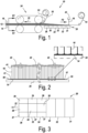
- Fig. 1 illustrates an example of an embodiment of the method according to the invention on a continuous production line 10 for producing polyisocyanurate insulation panels.
- Fig. 2 shows the view along F2 of a part of the continuous production line from Fig. 1 .
- a liquid polyisocyanurate foam formulation 18 is deposited on a foil 14, so that the foil is moistened in an uninterrupted manner by the liquid polyisocyanurate foam formulation in the direction at right angles to the direction of production across the entire width at the position where the liquid foam formulation is deposited on the foil 14.
- the example uses a number of spraying units 43 which are positioned across the width of the production line 10.
- Each of the spraying units 43 comprises a discrete number of spray nozzles 41 from which liquid polyisocyanurate foam formulation flows.
- the liquid polyisocyanurate foam formulation flows from a discrete number of spray nozzles 41.
- the spray nozzles are oriented in such a way that the liquid polyisocyanurate foam formulation flows vertically from the spray nozzles in the direction of the foil.
- the foil At the position where the liquid foam formulation 18 is deposited on the foil, the foil is supported by a heated table 20.
- the heated table 20 is arranged in a fixed position.
- a paper strip 55 is introduced next to the foil on both sides of the foil 14.
- the paper strip 55 is attached to the foil 14 on both sides by means of adhesive tape 57.
- the paper strips 55 are folded on both sides to a vertical position in the production line, wherein the polyisocyanurate foam bonds to these vertical paper strips. These paper strips 55 form the lateral edges of the produced polyisocyanurate insulation panel.
- liquid polyisocyanurate foam formulation 18 expands and reacts to form a polyisocyanurate foam 12 bonded to the foil 14.
- the foil 14 - with the liquid foam formulation on top thereof - is continuously passed through the production line in the direction of production 22 of the insulation panel.
- the heated table has a temperature of at least 30°C. Depending on the polyisocyanurate foam formulation, this temperature may be, for example 35°C or 45°C.
- the heated table 20 comprises six sections 31, 32, 33, 34, 35, 36 in the direction of production 22, wherein the temperature in these six sections 31, 32, 33, 34, 35, 36 can be adjusted and controlled separately.
- the foil 14 with the polyisocyanurate foam 18 on top thereof is passed through an oven downstream of the heated table 20 by means of and between a double belt 24.
- a second foil 16 is supplied above the foil 14 with the polyisocyanurate foam on top thereof.
- the foil 14 with the polyisocyanurate foam on top thereof and the second foil 16 are passed through the oven by means of and between the double belt 24.
- the liquid polyisocyanurate foam formulation continues to expand and react to form a polyisocyanurate foam bonded to and situated between the foil 14, the second foil 16 and the two paper strips 55.
- the vertical position of the running in of the second foil 16 is determined by the fact that the second foil 16 is passed under a roller 53.
- the vertical position of this roller 53 may be controlled by means of a control circuit depending on a measurement of the height of the polyisocyanurate foam upstream of the position of the roller 53.
- the height measurement of the foam across the width may preferably be performed by means of an optical measurement, for example by using a laser.
- Fig. 3 shows an example of the division into sections of the heated table 20 of the production line from Fig. 1 .
- the heated table 20 from Fig. 1 (and as shown in detail in Fig. 3 ) comprises six sections 31, 32, 33, 34, 35, 36 in the direction of production.
- the temperature in these six sections 31, 32, 33, 34, 35, 36 can be adjusted separately and set to the desired temperature.
- these sections comprise sensors and control circuits.
- the last three sections 34, 35, 36 upstream of the oven of the heated table 20 are each divided into three subsections 37, 38, 39 in the direction at right angles to the direction of production. These three subsections each comprise a central section 38 and two edge sections 37, 39. The central section 38 is at least double the width of each of the two edge sections 37, 39. In each of these nine subsections, the temperature can be adjusted and controlled separately with respect to the desired temperature. To this end, each subsection comprises sensors and a control circuit.
- An example of temperature adjustment in the successive sections is: 35°C in the first section 31; 35°C in the second section 32; 45°C in the third section 33; 50°C in each subsection 37, 38, 39 of the fourth section 34; 65°C in each subsection 37, 38, 39 of the fifth section 34; and 65°C in each subsection 37, 38, 39 of the sixth section 36.
- the temperature in each subsection which is intersected by the same line at right angles to the direction of production is thus adjusted to be identical. This is not necessarily the case for the invention.
- the temperature of each of the three subsections 37, 38, 39 of the last section 36 of the heated table 20 is adjusted to be identical to the temperature of the oven.
- Fig. 4 shows an example of a spraying unit 43 as may be used in the invention.
- a number of these spraying units 43 are positioned across the width of the production line. This is shown in Fig. 2 by means of a different type of spraying unit, i.e. the type of spraying unit shown in Fig. 5 .
- the spraying units 43 from Fig. 4 may be used.
- the spraying unit 43 from Fig. 4 comprises a central supply duct 45 for supplying the liquid polyisocyanurate foam formulation.
- the central supply duct 45 ends in a transverse distribution duct 47.
- the spraying units 43 from Fig. 4 comprise a second transverse distribution duct 49.
- the second transverse distribution duct 49 runs parallel to the transverse distribution duct 47; and is connected thereto via six connecting ducts 51.
- the liquid polyisocyanurate foam formulation can flow from the transverse distribution duct 47 into the second transverse distribution duct 49 via the connecting ducts 51.
- the six connecting ducts 51 are placed transversely with respect to the transverse distribution duct 47. In each case, two connecting ducts 51 are arranged symmetrically with respect to the central supply duct 45.
- the twelve spray nozzles 41 of the spraying unit 43 from Fig. 4 are positioned across the length of the second transverse distribution duct 49.
- Each spray nozzle 41 is connected to the second transverse distribution duct 49 via a spraying duct 48, placed transversely with respect to the second transverse distribution duct 49.
- two spraying ducts 48 are arranged symmetrically with respect to each connecting duct 51.
- the twelve spray nozzles 41 from the example of spraying unit 43 from Fig. 4 are circular and have a diameter of 11 mm.
- the distance D between every two successive spray nozzles 41 of the spraying unit 43 is 23 mm.
- the illustrated spraying unit 43 from Fig. 4 consists of two plastic injection-moulded parts which have been glued together.
- Spraying units 43 as shown in Fig. 4 are preferably used for producing polyisocyanurate insulation panels having a thickness of at least 60 mm.
- Fig. 5 shows another example of a spraying unit 43 as may be used with the invention.
- a number of these spraying units 43 may be positioned across the width of the production line. This is shown in Fig. 2 .
- the spraying unit 43 from Fig. 5 comprises a central supply duct 45 for supplying the liquid polyisocyanurate foam formulation.
- the central supply duct 45 ends in a transverse distribution duct 47 which passes the liquid polyisocyanurate foam formulation to twelve spray nozzles 41.
- the liquid polyisocyanurate foam formulation may flow from the spray nozzles 41 at right angles to the direction of production of the polyisocyanurate panel. This is illustrated in Fig. 2 .
- the spraying unit 43 from Fig. 5 comprises a number of spraying ducts 48, placed at right angles to the transverse distribution duct 47. Each spraying duct 48 passes a separate stream of the liquid polyisocyanurate foam formulation from the transverse distribution duct 47 to a spray nozzle 41.
- the length of the spraying ducts 48 decreases from spraying ducts which end in a centrally positioned spray nozzle or the centrally positioned spray nozzles, to the spraying ducts 48 which end in the most distal spray nozzles 41 with respect to the central supply duct 45.
- the twelve spray nozzles 41 of the spraying unit from Fig. 5 are circular.
- the spraying unit from Fig. 5 is composed of plastic injection-moulded parts.
- Spraying units 43 as shown in Fig. 5 are preferably used for producing insulation panels having a thickness of 60 mm or less.
- Fig. 6 shows a polyisocyanurate insulation panel as may be produced according to the method of the invention.
- the insulation panel comprises a rigid polyisocyanurate foam 12 between two foils 14, 16.
- the sides are formed by paper strips 55.
- These polyisocyanurate insulation panels are produced in full width on a production line as shown in Fig. 1 , in the example from Fig. 1 in a width of 1200 mm. If required, insulation panels may then be sawn to size from these insulation panels which are 1200 mm wide.
- the invention furthermore relates to the following list of numbered paragraphs:
- the present invention is by no means limited to the above-described embodiments, but such methods for producing a polyisocyanurate (PIR) insulation panel may be realised according to different variants without departing from the scope of the present invention.
- PIR polyisocyanurate
Landscapes
- Engineering & Computer Science (AREA)
- Manufacturing & Machinery (AREA)
- Mechanical Engineering (AREA)
- Physics & Mathematics (AREA)
- Health & Medical Sciences (AREA)
- Oral & Maxillofacial Surgery (AREA)
- Thermal Sciences (AREA)
- Casting Or Compression Moulding Of Plastics Or The Like (AREA)
- Manufacture Of Porous Articles, And Recovery And Treatment Of Waste Products (AREA)
Priority Applications (1)
| Application Number | Priority Date | Filing Date | Title |
|---|---|---|---|
| EP25186143.1A EP4600018A3 (de) | 2022-12-15 | 2023-12-06 | Verfahren zur herstellung einer platte |
Applications Claiming Priority (1)
| Application Number | Priority Date | Filing Date | Title |
|---|---|---|---|
| BE20226015A BE1031149B1 (nl) | 2022-12-15 | 2022-12-15 | Methode voor het produceren van een paneel |
Related Child Applications (1)
| Application Number | Title | Priority Date | Filing Date |
|---|---|---|---|
| EP25186143.1A Division EP4600018A3 (de) | 2022-12-15 | 2023-12-06 | Verfahren zur herstellung einer platte |
Publications (3)
| Publication Number | Publication Date |
|---|---|
| EP4385702A1 true EP4385702A1 (de) | 2024-06-19 |
| EP4385702C0 EP4385702C0 (de) | 2025-07-02 |
| EP4385702B1 EP4385702B1 (de) | 2025-07-02 |
Family
ID=84785085
Family Applications (2)
| Application Number | Title | Priority Date | Filing Date |
|---|---|---|---|
| EP23214722.3A Active EP4385702B1 (de) | 2022-12-15 | 2023-12-06 | Verfahren zur herstellung einer platte |
| EP25186143.1A Pending EP4600018A3 (de) | 2022-12-15 | 2023-12-06 | Verfahren zur herstellung einer platte |
Family Applications After (1)
| Application Number | Title | Priority Date | Filing Date |
|---|---|---|---|
| EP25186143.1A Pending EP4600018A3 (de) | 2022-12-15 | 2023-12-06 | Verfahren zur herstellung einer platte |
Country Status (4)
| Country | Link |
|---|---|
| EP (2) | EP4385702B1 (de) |
| BE (1) | BE1031149B1 (de) |
| ES (1) | ES3039334T3 (de) |
| PL (1) | PL4385702T3 (de) |
Cited By (2)
| Publication number | Priority date | Publication date | Assignee | Title |
|---|---|---|---|---|
| WO2026033356A1 (en) | 2024-08-08 | 2026-02-12 | Unilin, Bv | Insulation panel |
| BE1032827A1 (nl) | 2024-08-08 | 2026-03-03 | Unilin Bv | Isolatiepaneel |
Citations (8)
| Publication number | Priority date | Publication date | Assignee | Title |
|---|---|---|---|---|
| US3367818A (en) * | 1966-08-01 | 1968-02-06 | Allied Chem | Strengthening edges of foam sandwich structure |
| US20070092688A1 (en) * | 2005-10-24 | 2007-04-26 | Doesburg Van I | Polyurethane coating system |
| EP1790452A2 (de) * | 2005-11-25 | 2007-05-30 | Kingspan Research and Developments Limited | Herstellung von Dämmplatten |
| GB2481693A (en) * | 2010-07-02 | 2012-01-04 | Kingspan Holdings Irl Ltd | Composite insulation board |
| WO2020076529A1 (en) | 2018-10-09 | 2020-04-16 | Dow Global Technologies Llc | A rigid polyurethane foam formulation and foam made therefrom |
| WO2020076539A1 (en) | 2018-10-09 | 2020-04-16 | Dow Global Technologies Llc | A rigid polyurethane foam formulation and foam made therefrom |
| WO2021046022A1 (en) * | 2019-09-06 | 2021-03-11 | Dow Global Technologies Llc | A panel member production line |
| WO2022047102A1 (en) | 2020-08-28 | 2022-03-03 | Stepan Company | Systems and methods for computer vision assisted foam board processing |
Family Cites Families (4)
| Publication number | Priority date | Publication date | Assignee | Title |
|---|---|---|---|---|
| PT1445085E (pt) * | 2003-02-05 | 2008-12-22 | Alcan Tech & Man Ltd | Processo para fabricação de uma placa laminada |
| PL2737956T3 (pl) * | 2007-12-17 | 2020-11-16 | Basf Se | Sposób wytwarzania elementów kompozytowych na bazie tworzyw piankowych na bazie izocyjanianów |
| FR3088571B1 (fr) * | 2018-11-19 | 2021-12-17 | Gaztransport Et Technigaz | Procede et systeme de preparation d’un bloc de mousse polyurethane/polyisocyanurate d’un massif d’isolation thermique d’une cuve |
| EP3804939A1 (de) * | 2019-10-11 | 2021-04-14 | Covestro Deutschland AG | Verfahren und vorrichtung zur herstellung von schaum-verbundelementen |
-
2022
- 2022-12-15 BE BE20226015A patent/BE1031149B1/nl active IP Right Grant
-
2023
- 2023-12-06 EP EP23214722.3A patent/EP4385702B1/de active Active
- 2023-12-06 ES ES23214722T patent/ES3039334T3/es active Active
- 2023-12-06 PL PL23214722.3T patent/PL4385702T3/pl unknown
- 2023-12-06 EP EP25186143.1A patent/EP4600018A3/de active Pending
Patent Citations (8)
| Publication number | Priority date | Publication date | Assignee | Title |
|---|---|---|---|---|
| US3367818A (en) * | 1966-08-01 | 1968-02-06 | Allied Chem | Strengthening edges of foam sandwich structure |
| US20070092688A1 (en) * | 2005-10-24 | 2007-04-26 | Doesburg Van I | Polyurethane coating system |
| EP1790452A2 (de) * | 2005-11-25 | 2007-05-30 | Kingspan Research and Developments Limited | Herstellung von Dämmplatten |
| GB2481693A (en) * | 2010-07-02 | 2012-01-04 | Kingspan Holdings Irl Ltd | Composite insulation board |
| WO2020076529A1 (en) | 2018-10-09 | 2020-04-16 | Dow Global Technologies Llc | A rigid polyurethane foam formulation and foam made therefrom |
| WO2020076539A1 (en) | 2018-10-09 | 2020-04-16 | Dow Global Technologies Llc | A rigid polyurethane foam formulation and foam made therefrom |
| WO2021046022A1 (en) * | 2019-09-06 | 2021-03-11 | Dow Global Technologies Llc | A panel member production line |
| WO2022047102A1 (en) | 2020-08-28 | 2022-03-03 | Stepan Company | Systems and methods for computer vision assisted foam board processing |
Cited By (3)
| Publication number | Priority date | Publication date | Assignee | Title |
|---|---|---|---|---|
| WO2026033356A1 (en) | 2024-08-08 | 2026-02-12 | Unilin, Bv | Insulation panel |
| BE1032827A1 (nl) | 2024-08-08 | 2026-03-03 | Unilin Bv | Isolatiepaneel |
| BE1032843A1 (nl) | 2024-08-08 | 2026-03-10 | Unilin Bv | Isolatiepaneel |
Also Published As
| Publication number | Publication date |
|---|---|
| BE1031149B1 (nl) | 2024-07-15 |
| EP4600018A2 (de) | 2025-08-13 |
| BE1031149A1 (nl) | 2024-07-10 |
| PL4385702T3 (pl) | 2026-04-20 |
| ES3039334T3 (en) | 2025-10-20 |
| EP4385702C0 (de) | 2025-07-02 |
| EP4385702B1 (de) | 2025-07-02 |
| EP4600018A3 (de) | 2025-10-22 |
Similar Documents
| Publication | Publication Date | Title |
|---|---|---|
| EP4385702A1 (de) | Verfahren zur herstellung einer platte | |
| US6030559A (en) | Method for the continuous manufacture of plastic foam | |
| US6093481A (en) | Insulating sheathing with tough three-ply facers | |
| CA2707500A1 (en) | Methods for producing composite elements based on foams based on isocyanate | |
| KR20130133829A (ko) | 커버 층에 액체 반응 혼합물을 도포하기 위한 방법 및 디바이스 | |
| US20120141673A1 (en) | Sandwich composite elements | |
| US5817260A (en) | Method of using a heated metering device for foam production | |
| US12036766B2 (en) | Multilayer panel member | |
| CN105050787B (zh) | 用于两个或多个面板的同时和连续发泡的方法和装置 | |
| US9925701B2 (en) | Sandwich composite elements | |
| EP1562730B1 (de) | Verfahren und vorrichtung zum auftragen einer beschichtigung auf einen um eine achse rotierenden körper | |
| CN114302795B (zh) | 板构件生产线 | |
| EP4452592B1 (de) | Vorrichtung und verfahren zum auftragen eines aufschäumenden reaktionsgemisches auf ein laminiergerät unter verwendung einer divergierenden düse | |
| BE1031928B1 (nl) | Isolatiepaneel en methode voor het produceren van een isolatiepaneel | |
| CN121464027A (zh) | 用于生产波纹形层压板的方法 | |
| CN110248791A (zh) | 用于制备泡沫复合元件的方法和装置 | |
| US9381542B2 (en) | Methods for applying a foamable reaction mixture, high pressure device and device for producing sandwich composite elements | |
| WO2021121533A1 (en) | Method for producing a cementitious board, apparatus for producing a cementitious board, and cementitious board | |
| JPS5938902B2 (ja) | サンドイッチ板製造装置 | |
| JPS61112644A (ja) | サンドイッチ板製造装置 | |
| HK1021959A (en) | Foam insulation board faced with a tough polymeric film or composite thereof | |
| JPH11268052A (ja) | 建築用複合板の製造方法及び装置 | |
| PL215099B1 (pl) | Sposób wytwarzania płyt warstwowych i urządzenie do wytwarzania płyt warstwowych |
Legal Events
| Date | Code | Title | Description |
|---|---|---|---|
| PUAI | Public reference made under article 153(3) epc to a published international application that has entered the european phase |
Free format text: ORIGINAL CODE: 0009012 |
|
| STAA | Information on the status of an ep patent application or granted ep patent |
Free format text: STATUS: THE APPLICATION HAS BEEN PUBLISHED |
|
| AK | Designated contracting states |
Kind code of ref document: A1 Designated state(s): AL AT BE BG CH CY CZ DE DK EE ES FI FR GB GR HR HU IE IS IT LI LT LU LV MC ME MK MT NL NO PL PT RO RS SE SI SK SM TR |
|
| STAA | Information on the status of an ep patent application or granted ep patent |
Free format text: STATUS: REQUEST FOR EXAMINATION WAS MADE |
|
| 17P | Request for examination filed |
Effective date: 20241031 |
|
| RBV | Designated contracting states (corrected) |
Designated state(s): AL AT BE BG CH CY CZ DE DK EE ES FI FR GB GR HR HU IE IS IT LI LT LU LV MC ME MK MT NL NO PL PT RO RS SE SI SK SM TR |
|
| GRAP | Despatch of communication of intention to grant a patent |
Free format text: ORIGINAL CODE: EPIDOSNIGR1 |
|
| STAA | Information on the status of an ep patent application or granted ep patent |
Free format text: STATUS: GRANT OF PATENT IS INTENDED |
|
| RIC1 | Information provided on ipc code assigned before grant |
Ipc: B29L 7/00 20060101ALN20250306BHEP Ipc: B29C 63/00 20060101ALI20250306BHEP Ipc: B29C 44/46 20060101ALI20250306BHEP Ipc: B29C 44/34 20060101ALI20250306BHEP Ipc: B29C 44/32 20060101ALI20250306BHEP Ipc: B29C 44/28 20060101ALI20250306BHEP Ipc: B29C 35/00 20060101AFI20250306BHEP |
|
| INTG | Intention to grant announced |
Effective date: 20250313 |
|
| GRAS | Grant fee paid |
Free format text: ORIGINAL CODE: EPIDOSNIGR3 |
|
| GRAA | (expected) grant |
Free format text: ORIGINAL CODE: 0009210 |
|
| STAA | Information on the status of an ep patent application or granted ep patent |
Free format text: STATUS: THE PATENT HAS BEEN GRANTED |
|
| AK | Designated contracting states |
Kind code of ref document: B1 Designated state(s): AL AT BE BG CH CY CZ DE DK EE ES FI FR GB GR HR HU IE IS IT LI LT LU LV MC ME MK MT NL NO PL PT RO RS SE SI SK SM TR |
|
| REG | Reference to a national code |
Ref country code: GB Ref legal event code: FG4D |
|
| REG | Reference to a national code |
Ref country code: CH Ref legal event code: EP |
|
| REG | Reference to a national code |
Ref country code: DE Ref legal event code: R096 Ref document number: 602023004528 Country of ref document: DE |
|
| REG | Reference to a national code |
Ref country code: IE Ref legal event code: FG4D |
|
| U01 | Request for unitary effect filed |
Effective date: 20250703 |
|
| U07 | Unitary effect registered |
Designated state(s): AT BE BG DE DK EE FI FR IT LT LU LV MT NL PT RO SE SI Effective date: 20250710 |
|
| REG | Reference to a national code |
Ref country code: ES Ref legal event code: FG2A Ref document number: 3039334 Country of ref document: ES Kind code of ref document: T3 Effective date: 20251020 |
|
| PG25 | Lapsed in a contracting state [announced via postgrant information from national office to epo] |
Ref country code: IS Free format text: LAPSE BECAUSE OF FAILURE TO SUBMIT A TRANSLATION OF THE DESCRIPTION OR TO PAY THE FEE WITHIN THE PRESCRIBED TIME-LIMIT Effective date: 20251102 |
|
| PG25 | Lapsed in a contracting state [announced via postgrant information from national office to epo] |
Ref country code: NO Free format text: LAPSE BECAUSE OF FAILURE TO SUBMIT A TRANSLATION OF THE DESCRIPTION OR TO PAY THE FEE WITHIN THE PRESCRIBED TIME-LIMIT Effective date: 20251002 |
|
| PG25 | Lapsed in a contracting state [announced via postgrant information from national office to epo] |
Ref country code: HR Free format text: LAPSE BECAUSE OF FAILURE TO SUBMIT A TRANSLATION OF THE DESCRIPTION OR TO PAY THE FEE WITHIN THE PRESCRIBED TIME-LIMIT Effective date: 20250702 |
|
| PG25 | Lapsed in a contracting state [announced via postgrant information from national office to epo] |
Ref country code: GR Free format text: LAPSE BECAUSE OF FAILURE TO SUBMIT A TRANSLATION OF THE DESCRIPTION OR TO PAY THE FEE WITHIN THE PRESCRIBED TIME-LIMIT Effective date: 20251003 |
|
| PG25 | Lapsed in a contracting state [announced via postgrant information from national office to epo] |
Ref country code: CZ Free format text: LAPSE BECAUSE OF FAILURE TO SUBMIT A TRANSLATION OF THE DESCRIPTION OR TO PAY THE FEE WITHIN THE PRESCRIBED TIME-LIMIT Effective date: 20250702 |
|
| PG25 | Lapsed in a contracting state [announced via postgrant information from national office to epo] |
Ref country code: RS Free format text: LAPSE BECAUSE OF FAILURE TO SUBMIT A TRANSLATION OF THE DESCRIPTION OR TO PAY THE FEE WITHIN THE PRESCRIBED TIME-LIMIT Effective date: 20251002 |
|
| U20 | Renewal fee for the european patent with unitary effect paid |
Year of fee payment: 3 Effective date: 20251229 |
|
| PG25 | Lapsed in a contracting state [announced via postgrant information from national office to epo] |
Ref country code: SM Free format text: LAPSE BECAUSE OF FAILURE TO SUBMIT A TRANSLATION OF THE DESCRIPTION OR TO PAY THE FEE WITHIN THE PRESCRIBED TIME-LIMIT Effective date: 20250702 |
|
| PGFP | Annual fee paid to national office [announced via postgrant information from national office to epo] |
Ref country code: ES Payment date: 20260102 Year of fee payment: 3 |
|
| PG25 | Lapsed in a contracting state [announced via postgrant information from national office to epo] |
Ref country code: SK Free format text: LAPSE BECAUSE OF FAILURE TO SUBMIT A TRANSLATION OF THE DESCRIPTION OR TO PAY THE FEE WITHIN THE PRESCRIBED TIME-LIMIT Effective date: 20250702 |