EP4389629A2 - Palette - Google Patents
Palette Download PDFInfo
- Publication number
- EP4389629A2 EP4389629A2 EP24175580.0A EP24175580A EP4389629A2 EP 4389629 A2 EP4389629 A2 EP 4389629A2 EP 24175580 A EP24175580 A EP 24175580A EP 4389629 A2 EP4389629 A2 EP 4389629A2
- Authority
- EP
- European Patent Office
- Prior art keywords
- arrangement
- coupling
- skid
- support arrangement
- support
- Prior art date
- Legal status (The legal status is an assumption and is not a legal conclusion. Google has not performed a legal analysis and makes no representation as to the accuracy of the status listed.)
- Granted
Links
Images


Classifications
-
- B—PERFORMING OPERATIONS; TRANSPORTING
- B65—CONVEYING; PACKING; STORING; HANDLING THIN OR FILAMENTARY MATERIAL
- B65D—CONTAINERS FOR STORAGE OR TRANSPORT OF ARTICLES OR MATERIALS, e.g. BAGS, BARRELS, BOTTLES, BOXES, CANS, CARTONS, CRATES, DRUMS, JARS, TANKS, HOPPERS, FORWARDING CONTAINERS; ACCESSORIES, CLOSURES, OR FITTINGS THEREFOR; PACKAGING ELEMENTS; PACKAGES
- B65D19/00—Pallets or like platforms, with or without side walls, for supporting loads to be lifted or lowered
- B65D19/0004—Rigid pallets without side walls
- B65D19/0006—Rigid pallets without side walls the load supporting surface being made of a single element
- B65D19/003—Rigid pallets without side walls the load supporting surface being made of a single element forming discontinuous or non-planar contact surfaces
- B65D19/0042—Rigid pallets without side walls the load supporting surface being made of a single element forming discontinuous or non-planar contact surfaces the base surface being made of more than one element
- B65D19/0046—Rigid pallets without side walls the load supporting surface being made of a single element forming discontinuous or non-planar contact surfaces the base surface being made of more than one element forming discontinuous or non-planar contact surfaces
- B65D19/0048—Rigid pallets without side walls the load supporting surface being made of a single element forming discontinuous or non-planar contact surfaces the base surface being made of more than one element forming discontinuous or non-planar contact surfaces and each contact surface having a stringer-like shape
-
- B—PERFORMING OPERATIONS; TRANSPORTING
- B65—CONVEYING; PACKING; STORING; HANDLING THIN OR FILAMENTARY MATERIAL
- B65D—CONTAINERS FOR STORAGE OR TRANSPORT OF ARTICLES OR MATERIALS, e.g. BAGS, BARRELS, BOTTLES, BOXES, CANS, CARTONS, CRATES, DRUMS, JARS, TANKS, HOPPERS, FORWARDING CONTAINERS; ACCESSORIES, CLOSURES, OR FITTINGS THEREFOR; PACKAGING ELEMENTS; PACKAGES
- B65D19/00—Pallets or like platforms, with or without side walls, for supporting loads to be lifted or lowered
- B65D19/0004—Rigid pallets without side walls
- B65D19/0006—Rigid pallets without side walls the load supporting surface being made of a single element
- B65D19/003—Rigid pallets without side walls the load supporting surface being made of a single element forming discontinuous or non-planar contact surfaces
- B65D19/0032—Rigid pallets without side walls the load supporting surface being made of a single element forming discontinuous or non-planar contact surfaces the base surface being made of a single element
- B65D19/0036—Rigid pallets without side walls the load supporting surface being made of a single element forming discontinuous or non-planar contact surfaces the base surface being made of a single element forming discontinuous or non-planar contact surfaces
- B65D19/004—Rigid pallets without side walls the load supporting surface being made of a single element forming discontinuous or non-planar contact surfaces the base surface being made of a single element forming discontinuous or non-planar contact surfaces and each contact surface having a discrete foot-like shape
-
- B—PERFORMING OPERATIONS; TRANSPORTING
- B65—CONVEYING; PACKING; STORING; HANDLING THIN OR FILAMENTARY MATERIAL
- B65D—CONTAINERS FOR STORAGE OR TRANSPORT OF ARTICLES OR MATERIALS, e.g. BAGS, BARRELS, BOTTLES, BOXES, CANS, CARTONS, CRATES, DRUMS, JARS, TANKS, HOPPERS, FORWARDING CONTAINERS; ACCESSORIES, CLOSURES, OR FITTINGS THEREFOR; PACKAGING ELEMENTS; PACKAGES
- B65D2519/00—Pallets or like platforms, with or without side walls, for supporting loads to be lifted or lowered
- B65D2519/00004—Details relating to pallets
- B65D2519/00009—Materials
- B65D2519/00014—Materials for the load supporting surface
- B65D2519/00029—Wood
-
- B—PERFORMING OPERATIONS; TRANSPORTING
- B65—CONVEYING; PACKING; STORING; HANDLING THIN OR FILAMENTARY MATERIAL
- B65D—CONTAINERS FOR STORAGE OR TRANSPORT OF ARTICLES OR MATERIALS, e.g. BAGS, BARRELS, BOTTLES, BOXES, CANS, CARTONS, CRATES, DRUMS, JARS, TANKS, HOPPERS, FORWARDING CONTAINERS; ACCESSORIES, CLOSURES, OR FITTINGS THEREFOR; PACKAGING ELEMENTS; PACKAGES
- B65D2519/00—Pallets or like platforms, with or without side walls, for supporting loads to be lifted or lowered
- B65D2519/00004—Details relating to pallets
- B65D2519/00009—Materials
- B65D2519/00014—Materials for the load supporting surface
- B65D2519/00034—Plastic
-
- B—PERFORMING OPERATIONS; TRANSPORTING
- B65—CONVEYING; PACKING; STORING; HANDLING THIN OR FILAMENTARY MATERIAL
- B65D—CONTAINERS FOR STORAGE OR TRANSPORT OF ARTICLES OR MATERIALS, e.g. BAGS, BARRELS, BOTTLES, BOXES, CANS, CARTONS, CRATES, DRUMS, JARS, TANKS, HOPPERS, FORWARDING CONTAINERS; ACCESSORIES, CLOSURES, OR FITTINGS THEREFOR; PACKAGING ELEMENTS; PACKAGES
- B65D2519/00—Pallets or like platforms, with or without side walls, for supporting loads to be lifted or lowered
- B65D2519/00004—Details relating to pallets
- B65D2519/00009—Materials
- B65D2519/00014—Materials for the load supporting surface
- B65D2519/00039—Agglomerates, i.e. different materials mixed together
-
- B—PERFORMING OPERATIONS; TRANSPORTING
- B65—CONVEYING; PACKING; STORING; HANDLING THIN OR FILAMENTARY MATERIAL
- B65D—CONTAINERS FOR STORAGE OR TRANSPORT OF ARTICLES OR MATERIALS, e.g. BAGS, BARRELS, BOTTLES, BOXES, CANS, CARTONS, CRATES, DRUMS, JARS, TANKS, HOPPERS, FORWARDING CONTAINERS; ACCESSORIES, CLOSURES, OR FITTINGS THEREFOR; PACKAGING ELEMENTS; PACKAGES
- B65D2519/00—Pallets or like platforms, with or without side walls, for supporting loads to be lifted or lowered
- B65D2519/00004—Details relating to pallets
- B65D2519/00009—Materials
- B65D2519/00049—Materials for the base surface
- B65D2519/00064—Wood
-
- B—PERFORMING OPERATIONS; TRANSPORTING
- B65—CONVEYING; PACKING; STORING; HANDLING THIN OR FILAMENTARY MATERIAL
- B65D—CONTAINERS FOR STORAGE OR TRANSPORT OF ARTICLES OR MATERIALS, e.g. BAGS, BARRELS, BOTTLES, BOXES, CANS, CARTONS, CRATES, DRUMS, JARS, TANKS, HOPPERS, FORWARDING CONTAINERS; ACCESSORIES, CLOSURES, OR FITTINGS THEREFOR; PACKAGING ELEMENTS; PACKAGES
- B65D2519/00—Pallets or like platforms, with or without side walls, for supporting loads to be lifted or lowered
- B65D2519/00004—Details relating to pallets
- B65D2519/00009—Materials
- B65D2519/00049—Materials for the base surface
- B65D2519/00069—Plastic
-
- B—PERFORMING OPERATIONS; TRANSPORTING
- B65—CONVEYING; PACKING; STORING; HANDLING THIN OR FILAMENTARY MATERIAL
- B65D—CONTAINERS FOR STORAGE OR TRANSPORT OF ARTICLES OR MATERIALS, e.g. BAGS, BARRELS, BOTTLES, BOXES, CANS, CARTONS, CRATES, DRUMS, JARS, TANKS, HOPPERS, FORWARDING CONTAINERS; ACCESSORIES, CLOSURES, OR FITTINGS THEREFOR; PACKAGING ELEMENTS; PACKAGES
- B65D2519/00—Pallets or like platforms, with or without side walls, for supporting loads to be lifted or lowered
- B65D2519/00004—Details relating to pallets
- B65D2519/00009—Materials
- B65D2519/00049—Materials for the base surface
- B65D2519/00074—Agglomerates, i.e. different materials mixed together
-
- B—PERFORMING OPERATIONS; TRANSPORTING
- B65—CONVEYING; PACKING; STORING; HANDLING THIN OR FILAMENTARY MATERIAL
- B65D—CONTAINERS FOR STORAGE OR TRANSPORT OF ARTICLES OR MATERIALS, e.g. BAGS, BARRELS, BOTTLES, BOXES, CANS, CARTONS, CRATES, DRUMS, JARS, TANKS, HOPPERS, FORWARDING CONTAINERS; ACCESSORIES, CLOSURES, OR FITTINGS THEREFOR; PACKAGING ELEMENTS; PACKAGES
- B65D2519/00—Pallets or like platforms, with or without side walls, for supporting loads to be lifted or lowered
- B65D2519/00004—Details relating to pallets
- B65D2519/00009—Materials
- B65D2519/00119—Materials for the construction of the reinforcements
- B65D2519/00129—Metal
-
- B—PERFORMING OPERATIONS; TRANSPORTING
- B65—CONVEYING; PACKING; STORING; HANDLING THIN OR FILAMENTARY MATERIAL
- B65D—CONTAINERS FOR STORAGE OR TRANSPORT OF ARTICLES OR MATERIALS, e.g. BAGS, BARRELS, BOTTLES, BOXES, CANS, CARTONS, CRATES, DRUMS, JARS, TANKS, HOPPERS, FORWARDING CONTAINERS; ACCESSORIES, CLOSURES, OR FITTINGS THEREFOR; PACKAGING ELEMENTS; PACKAGES
- B65D2519/00—Pallets or like platforms, with or without side walls, for supporting loads to be lifted or lowered
- B65D2519/00004—Details relating to pallets
- B65D2519/00009—Materials
- B65D2519/00119—Materials for the construction of the reinforcements
- B65D2519/00139—Plastic
-
- B—PERFORMING OPERATIONS; TRANSPORTING
- B65—CONVEYING; PACKING; STORING; HANDLING THIN OR FILAMENTARY MATERIAL
- B65D—CONTAINERS FOR STORAGE OR TRANSPORT OF ARTICLES OR MATERIALS, e.g. BAGS, BARRELS, BOTTLES, BOXES, CANS, CARTONS, CRATES, DRUMS, JARS, TANKS, HOPPERS, FORWARDING CONTAINERS; ACCESSORIES, CLOSURES, OR FITTINGS THEREFOR; PACKAGING ELEMENTS; PACKAGES
- B65D2519/00—Pallets or like platforms, with or without side walls, for supporting loads to be lifted or lowered
- B65D2519/00004—Details relating to pallets
- B65D2519/00258—Overall construction
- B65D2519/00263—Overall construction of the pallet
- B65D2519/00268—Overall construction of the pallet made of one piece
-
- B—PERFORMING OPERATIONS; TRANSPORTING
- B65—CONVEYING; PACKING; STORING; HANDLING THIN OR FILAMENTARY MATERIAL
- B65D—CONTAINERS FOR STORAGE OR TRANSPORT OF ARTICLES OR MATERIALS, e.g. BAGS, BARRELS, BOTTLES, BOXES, CANS, CARTONS, CRATES, DRUMS, JARS, TANKS, HOPPERS, FORWARDING CONTAINERS; ACCESSORIES, CLOSURES, OR FITTINGS THEREFOR; PACKAGING ELEMENTS; PACKAGES
- B65D2519/00—Pallets or like platforms, with or without side walls, for supporting loads to be lifted or lowered
- B65D2519/00004—Details relating to pallets
- B65D2519/00258—Overall construction
- B65D2519/00263—Overall construction of the pallet
- B65D2519/00273—Overall construction of the pallet made of more than one piece
-
- B—PERFORMING OPERATIONS; TRANSPORTING
- B65—CONVEYING; PACKING; STORING; HANDLING THIN OR FILAMENTARY MATERIAL
- B65D—CONTAINERS FOR STORAGE OR TRANSPORT OF ARTICLES OR MATERIALS, e.g. BAGS, BARRELS, BOTTLES, BOXES, CANS, CARTONS, CRATES, DRUMS, JARS, TANKS, HOPPERS, FORWARDING CONTAINERS; ACCESSORIES, CLOSURES, OR FITTINGS THEREFOR; PACKAGING ELEMENTS; PACKAGES
- B65D2519/00—Pallets or like platforms, with or without side walls, for supporting loads to be lifted or lowered
- B65D2519/00004—Details relating to pallets
- B65D2519/00258—Overall construction
- B65D2519/00283—Overall construction of the load supporting surface
- B65D2519/00288—Overall construction of the load supporting surface made of one piece
-
- B—PERFORMING OPERATIONS; TRANSPORTING
- B65—CONVEYING; PACKING; STORING; HANDLING THIN OR FILAMENTARY MATERIAL
- B65D—CONTAINERS FOR STORAGE OR TRANSPORT OF ARTICLES OR MATERIALS, e.g. BAGS, BARRELS, BOTTLES, BOXES, CANS, CARTONS, CRATES, DRUMS, JARS, TANKS, HOPPERS, FORWARDING CONTAINERS; ACCESSORIES, CLOSURES, OR FITTINGS THEREFOR; PACKAGING ELEMENTS; PACKAGES
- B65D2519/00—Pallets or like platforms, with or without side walls, for supporting loads to be lifted or lowered
- B65D2519/00004—Details relating to pallets
- B65D2519/00258—Overall construction
- B65D2519/00283—Overall construction of the load supporting surface
- B65D2519/00308—Overall construction of the load supporting surface grid type, e.g. perforated plate
-
- B—PERFORMING OPERATIONS; TRANSPORTING
- B65—CONVEYING; PACKING; STORING; HANDLING THIN OR FILAMENTARY MATERIAL
- B65D—CONTAINERS FOR STORAGE OR TRANSPORT OF ARTICLES OR MATERIALS, e.g. BAGS, BARRELS, BOTTLES, BOXES, CANS, CARTONS, CRATES, DRUMS, JARS, TANKS, HOPPERS, FORWARDING CONTAINERS; ACCESSORIES, CLOSURES, OR FITTINGS THEREFOR; PACKAGING ELEMENTS; PACKAGES
- B65D2519/00—Pallets or like platforms, with or without side walls, for supporting loads to be lifted or lowered
- B65D2519/00004—Details relating to pallets
- B65D2519/00258—Overall construction
- B65D2519/00313—Overall construction of the base surface
- B65D2519/00318—Overall construction of the base surface made of one piece
-
- B—PERFORMING OPERATIONS; TRANSPORTING
- B65—CONVEYING; PACKING; STORING; HANDLING THIN OR FILAMENTARY MATERIAL
- B65D—CONTAINERS FOR STORAGE OR TRANSPORT OF ARTICLES OR MATERIALS, e.g. BAGS, BARRELS, BOTTLES, BOXES, CANS, CARTONS, CRATES, DRUMS, JARS, TANKS, HOPPERS, FORWARDING CONTAINERS; ACCESSORIES, CLOSURES, OR FITTINGS THEREFOR; PACKAGING ELEMENTS; PACKAGES
- B65D2519/00—Pallets or like platforms, with or without side walls, for supporting loads to be lifted or lowered
- B65D2519/00004—Details relating to pallets
- B65D2519/00258—Overall construction
- B65D2519/00313—Overall construction of the base surface
- B65D2519/00323—Overall construction of the base surface made of more than one piece
-
- B—PERFORMING OPERATIONS; TRANSPORTING
- B65—CONVEYING; PACKING; STORING; HANDLING THIN OR FILAMENTARY MATERIAL
- B65D—CONTAINERS FOR STORAGE OR TRANSPORT OF ARTICLES OR MATERIALS, e.g. BAGS, BARRELS, BOTTLES, BOXES, CANS, CARTONS, CRATES, DRUMS, JARS, TANKS, HOPPERS, FORWARDING CONTAINERS; ACCESSORIES, CLOSURES, OR FITTINGS THEREFOR; PACKAGING ELEMENTS; PACKAGES
- B65D2519/00—Pallets or like platforms, with or without side walls, for supporting loads to be lifted or lowered
- B65D2519/00004—Details relating to pallets
- B65D2519/00258—Overall construction
- B65D2519/00313—Overall construction of the base surface
- B65D2519/00328—Overall construction of the base surface shape of the contact surface of the base
- B65D2519/00333—Overall construction of the base surface shape of the contact surface of the base contact surface having a stringer-like shape
-
- B—PERFORMING OPERATIONS; TRANSPORTING
- B65—CONVEYING; PACKING; STORING; HANDLING THIN OR FILAMENTARY MATERIAL
- B65D—CONTAINERS FOR STORAGE OR TRANSPORT OF ARTICLES OR MATERIALS, e.g. BAGS, BARRELS, BOTTLES, BOXES, CANS, CARTONS, CRATES, DRUMS, JARS, TANKS, HOPPERS, FORWARDING CONTAINERS; ACCESSORIES, CLOSURES, OR FITTINGS THEREFOR; PACKAGING ELEMENTS; PACKAGES
- B65D2519/00—Pallets or like platforms, with or without side walls, for supporting loads to be lifted or lowered
- B65D2519/00004—Details relating to pallets
- B65D2519/00258—Overall construction
- B65D2519/00313—Overall construction of the base surface
- B65D2519/00328—Overall construction of the base surface shape of the contact surface of the base
- B65D2519/00338—Overall construction of the base surface shape of the contact surface of the base contact surface having a discrete foot-like shape
-
- B—PERFORMING OPERATIONS; TRANSPORTING
- B65—CONVEYING; PACKING; STORING; HANDLING THIN OR FILAMENTARY MATERIAL
- B65D—CONTAINERS FOR STORAGE OR TRANSPORT OF ARTICLES OR MATERIALS, e.g. BAGS, BARRELS, BOTTLES, BOXES, CANS, CARTONS, CRATES, DRUMS, JARS, TANKS, HOPPERS, FORWARDING CONTAINERS; ACCESSORIES, CLOSURES, OR FITTINGS THEREFOR; PACKAGING ELEMENTS; PACKAGES
- B65D2519/00—Pallets or like platforms, with or without side walls, for supporting loads to be lifted or lowered
- B65D2519/00004—Details relating to pallets
- B65D2519/00258—Overall construction
- B65D2519/00313—Overall construction of the base surface
- B65D2519/00363—Overall construction of the base surface grid type, e.g. perforated plate
-
- B—PERFORMING OPERATIONS; TRANSPORTING
- B65—CONVEYING; PACKING; STORING; HANDLING THIN OR FILAMENTARY MATERIAL
- B65D—CONTAINERS FOR STORAGE OR TRANSPORT OF ARTICLES OR MATERIALS, e.g. BAGS, BARRELS, BOTTLES, BOXES, CANS, CARTONS, CRATES, DRUMS, JARS, TANKS, HOPPERS, FORWARDING CONTAINERS; ACCESSORIES, CLOSURES, OR FITTINGS THEREFOR; PACKAGING ELEMENTS; PACKAGES
- B65D2519/00—Pallets or like platforms, with or without side walls, for supporting loads to be lifted or lowered
- B65D2519/00004—Details relating to pallets
- B65D2519/00258—Overall construction
- B65D2519/00398—Overall construction reinforcements
- B65D2519/00402—Integral, e.g. ribs
-
- B—PERFORMING OPERATIONS; TRANSPORTING
- B65—CONVEYING; PACKING; STORING; HANDLING THIN OR FILAMENTARY MATERIAL
- B65D—CONTAINERS FOR STORAGE OR TRANSPORT OF ARTICLES OR MATERIALS, e.g. BAGS, BARRELS, BOTTLES, BOXES, CANS, CARTONS, CRATES, DRUMS, JARS, TANKS, HOPPERS, FORWARDING CONTAINERS; ACCESSORIES, CLOSURES, OR FITTINGS THEREFOR; PACKAGING ELEMENTS; PACKAGES
- B65D2519/00—Pallets or like platforms, with or without side walls, for supporting loads to be lifted or lowered
- B65D2519/00004—Details relating to pallets
- B65D2519/00258—Overall construction
- B65D2519/00398—Overall construction reinforcements
- B65D2519/00432—Non-integral, e.g. inserts
- B65D2519/00437—Non-integral, e.g. inserts on the load supporting surface
-
- B—PERFORMING OPERATIONS; TRANSPORTING
- B65—CONVEYING; PACKING; STORING; HANDLING THIN OR FILAMENTARY MATERIAL
- B65D—CONTAINERS FOR STORAGE OR TRANSPORT OF ARTICLES OR MATERIALS, e.g. BAGS, BARRELS, BOTTLES, BOXES, CANS, CARTONS, CRATES, DRUMS, JARS, TANKS, HOPPERS, FORWARDING CONTAINERS; ACCESSORIES, CLOSURES, OR FITTINGS THEREFOR; PACKAGING ELEMENTS; PACKAGES
- B65D2519/00—Pallets or like platforms, with or without side walls, for supporting loads to be lifted or lowered
- B65D2519/00004—Details relating to pallets
- B65D2519/00258—Overall construction
- B65D2519/00398—Overall construction reinforcements
- B65D2519/00432—Non-integral, e.g. inserts
- B65D2519/00442—Non-integral, e.g. inserts on the base surface
-
- B—PERFORMING OPERATIONS; TRANSPORTING
- B65—CONVEYING; PACKING; STORING; HANDLING THIN OR FILAMENTARY MATERIAL
- B65D—CONTAINERS FOR STORAGE OR TRANSPORT OF ARTICLES OR MATERIALS, e.g. BAGS, BARRELS, BOTTLES, BOXES, CANS, CARTONS, CRATES, DRUMS, JARS, TANKS, HOPPERS, FORWARDING CONTAINERS; ACCESSORIES, CLOSURES, OR FITTINGS THEREFOR; PACKAGING ELEMENTS; PACKAGES
- B65D2519/00—Pallets or like platforms, with or without side walls, for supporting loads to be lifted or lowered
- B65D2519/00004—Details relating to pallets
- B65D2519/00547—Connections
- B65D2519/00552—Structures connecting the constitutive elements of the pallet to each other, i.e. load supporting surface, base surface and/or separate spacer
- B65D2519/00557—Structures connecting the constitutive elements of the pallet to each other, i.e. load supporting surface, base surface and/or separate spacer without separate auxiliary elements
- B65D2519/00567—Structures connecting the constitutive elements of the pallet to each other, i.e. load supporting surface, base surface and/or separate spacer without separate auxiliary elements mechanical connection, e.g. snap-fitted
-
- B—PERFORMING OPERATIONS; TRANSPORTING
- B65—CONVEYING; PACKING; STORING; HANDLING THIN OR FILAMENTARY MATERIAL
- B65D—CONTAINERS FOR STORAGE OR TRANSPORT OF ARTICLES OR MATERIALS, e.g. BAGS, BARRELS, BOTTLES, BOXES, CANS, CARTONS, CRATES, DRUMS, JARS, TANKS, HOPPERS, FORWARDING CONTAINERS; ACCESSORIES, CLOSURES, OR FITTINGS THEREFOR; PACKAGING ELEMENTS; PACKAGES
- B65D2519/00—Pallets or like platforms, with or without side walls, for supporting loads to be lifted or lowered
- B65D2519/00004—Details relating to pallets
- B65D2519/00736—Details
- B65D2519/0098—Dismountable elements
- B65D2519/0099—Dismountable elements single dismountable pallet element, e.g. for replacement
Definitions
- the invention relates to a pallet according to the preamble of claim 1. Furthermore, the invention is directed to a support arrangement for such a pallet. The invention is also directed to a skid arrangement for such a pallet.
- Pallets are well known from the state of the art due to obvious prior use. In practice, they have proven themselves to be particularly useful for transporting and storing goods.
- U Plastic pallets are known, each of which has an upper part and a lower part as well as a detachable plug-in device arranged between them.
- the plug-in device is formed by plug-in bodies with plug-in projections connected to one part and plug-in body receptacles with plug-in projection openings arranged on the other part, which are connected to one another in a bayonet-like manner when assembled.
- the handling of this known pallet is often unsatisfactory.
- the EP 2 216 255 A1 discloses a pallet with a deck and downward-facing pallet feet and runners.
- the runners can be detachably connected to a pallet body and can be removed from the pallet body without any tools.
- a runner is positively connected to three pallet feet each. There is a detachable locking connection between the pallet body and the runners.
- the pallet disclosed has several feet on its underside. Fastening elements for detachable fastening of at least one runner are provided on at least two of the feet.
- the fastening element is designed as a click connection, snap connection and/or snap lock.
- the known pallet has a support plate which has legs at the bottom.
- the support plate and legs are connected to each other in an interchangeable manner.
- the interchangeable connection of the legs to the support plate is advantageously achieved by means of detachable connections, in particular clips.
- the clips enable quick assembly and disassembly.
- a known pallet comprises a cover means and a base as well as spacers arranged between them. Each spacer is detachably attached to the cover means and the base by means of a plug-in arrangement. Each spacer has a cylinder with groove-like recesses arranged on the circumference, each of which has an entrance for a tooth on the cover means and the base. A bayonet connection is present in the assembled state.
- the US$5,445,084 discloses a transport pallet whose longitudinal support beams are attached to a support surface via detachable fixing devices.
- Each fixing device has at least one opening formed in an upper part of the longitudinal support beam, which allows the reception of an element in order to connect the support surface to the longitudinal support beam.
- the locking element comprises a bayonet-like locking part with a holding plate and a cylinder part from which projections project radially.
- the US 2014/000494 A1 discloses a modular pallet with a pallet-like platform to which a substructure can be detachably connected.
- the connections themselves are, for example, dovetail, bayonet or other fitting connections.
- the invention is based on the object of providing an improved pallet.
- a pallet is to be created which is particularly simple and easy to handle or extremely user-friendly.
- a corresponding support arrangement and skid arrangement for such a pallet are also to be supplied.
- the pallet according to the invention according to claim 1 can be used as a storage, display or transport pallet. It can be converted accordingly if required. If the pallet is free of the skid arrangements, it is particularly light and thus extremely easy to handle, which is particularly advantageous when lifting manually. It is then preferably visually extremely appealing and can preferably also be used as a display pallet for presenting goods. If the skid arrangements are mounted, the pallet is particularly suitable for use in a warehouse, in particular high-bay warehouses, and/or in automated conveyor systems, such as chain conveyor systems. It is then, according to a preferred embodiment, with appropriate design of the skid arrangements, preferably particularly easy to move or slide on a surface. Damaged skid arrangements are particularly easy to dismantle or replace. The pallet is preferably designed as a reusable pallet.
- the support arrangement has at least one support surface, which is advantageously opposite the at least one standing surface or faces upwards. Goods can be arranged there.
- the support arrangement is preferably rigid. It is expedient if the support arrangement is symmetrical or essentially symmetrical with respect to a main or symmetry plane. It is preferably formed in one piece.
- the runner arrangements are preferably identical. They are advantageously symmetrical or essentially symmetrical with respect to a symmetry or main plane. It is expedient if each runner arrangement is rigid. Preferably, each runner arrangement has at least one standing surface.
- the at least one runner arrangement has a width in its transverse extension that is smaller, in particular significantly smaller, than the width of the support arrangement.
- the at least one runner arrangement has a length that corresponds (approximately) to the length of the support arrangement.
- the at least one runner arrangement is, for example, (slightly) longer than the support arrangement.
- the coupling arrangements are preferably identical. They preferably enable a force-fitting and/or form-fitting connection between the support arrangement and the respective skid arrangement.
- At least one surface on the support arrangement and/or respective runner arrangement has an increased roughness and/or at least one groove, preferably a plurality of grooves.
- the support assembly has at least one shaped outer edge to allow safe stacking of empty support assemblies and/or pallets.
- the design according to which the support arrangement and the skid arrangements can be decoupled from one another using the respective coupling arrangement, allows the pallet to be converted particularly easily. Conversions can be carried out as often as required, which is extremely user-friendly.
- the pallet allows a particularly secure and resilient coupling between the support arrangement and the respective skid arrangement.
- the coupling devices differ, for example, in their operating principle, their structure, their coupling movement and/or their decoupling movement.
- the coupling devices are preferably arranged at a distance from one another.
- the first coupling device preferably allows coupling or decoupling by a combination of a plug-in or axial movement and a rotational or pivoting movement of the support arrangement and the respective skid arrangement relative to one another. In use, it prevents in particular a separation between the support arrangement and the respective skid arrangement perpendicular to the at least one support surface or standing surface.
- the dovetail device is preferably designed as a dovetail connection or guide.
- the dovetail device is in particular capable of holding the respective skid arrangement securely to the support arrangement. In use, it prevents in particular a separation between the support arrangement and the respective skid arrangement in a longitudinal direction of the skid arrangement and perpendicular to the at least one support surface or standing surface.
- the at least one second coupling device is particularly easy to handle and can bear loads.
- the at least one second coupling means is designed, for example, as a groove, in particular a trapezoidal groove or dovetail groove.
- the at least one second counter-coupling means is designed, for example, as a pin or dovetail body. An inverted arrangement is alternatively possible.
- the pallet is chemically treated or coated at least in parts, preferably completely, for increased flame or fire protection.
- the support arrangement according to dependent claim 11 comprises in particular a first coupling part, at least one second coupling means or second coupling part, preferably arranged on a respective partial block, and/or at least one locking means.
- the skid arrangement according to dependent claim 12 comprises in particular a first counter-coupling part, at least one second counter-coupling means or second counter-coupling part, preferably arranged on a respective partial block, and/or at least one counter-latching means.
- the design according to subclaim 2 is again particularly user-friendly.
- the at least two runner arrangements can be arranged on the support arrangement without tools. It is advantageous if the runner arrangements can be decoupled or removed from the support arrangement without tools.
- the support arrangement according to subclaim 3 is itself preferably designed like a pallet. This creates the possibility of using a lifting device, such as a pallet truck, to reach under a support plate of the support arrangement and thus lift the pallet and any goods arranged on it.
- a lifting device such as a pallet truck
- the design according to subclaim 4 is extremely user-friendly.
- the pallet has very few components or individual parts.
- the first coupling part according to the dependent claim 5 preferably has at least one retaining web.
- the first counter-coupling part comprises preferably at least one retaining projection. They are preferably displaceable or pivotable relative to one another. An inverted arrangement is alternatively possible.
- the first partial blocks according to subclaims 6, 7 advantageously form at least one overall block in the assembled state of the respective runner arrangement.
- a locking connection acts between the support arrangement and the respective skid arrangement in the assembled state of the respective skid arrangement, which can preferably be brought about and/or released again without tools.
- Each safety locking device preferably has a locking means arranged on the support arrangement and a counter-locking means arranged on the respective skid arrangement.
- the locking means is designed, for example, as a projection, such as a nose.
- the counter-locking means is designed, for example, as an opening, recess or the like. It is expedient if the safety locking devices are able to prevent a pivoting movement between the support arrangement and the respective skid arrangement in their locking position.
- the respective safety locking device preferably also forms an end stop when assembling a skid arrangement, which simplifies assembly. An inverted arrangement is alternatively possible.
- the at least one sensor according to the dependent claim 10 is designed, for example, as a temperature sensor, motion sensor, acceleration sensor, weight sensor, geotracking sensor, charging history sensor, humidity sensor, alignment sensor, such as in the form of a spirit level, or anti-theft sensor, for example in the form of a seal, so that goods arranged on the support arrangement are present.
- the sign provides, for example, Information regarding recycling including the date of manufacture, age of the pallet, its composition and/or the owner.
- the at least one receiving space is formed, for example, by a hollow chamber of the support arrangement or skid arrangement. It is preferably spatially delimited by at least one web.
- At least one sensor is accommodated in the at least one receiving space.
- Information from the at least one sensor can be read out, in particular wirelessly, for example by at least one transmission module of the sensor, which works for example with radio, such as Bluetooth or mobile radio, infrared or the like. Local transmission and long-distance transmission are possible.
- the at least one sensor is designed as an RFID sensor. It is useful if the pallet contains at least one marker in order to obtain information about the pallet.
- the support arrangement and/or the runner arrangements are of lightweight construction. They are preferably recyclable. It is expedient if the support arrangement and/or the runner arrangements comprise renewable raw materials, such as wood fibers. Alternatively or additionally, the support arrangement and/or the runner arrangements comprise biopolymers.
- the support arrangement can be manufactured, for example, by injection molding or pressing.
- the skid arrangements can be manufactured, for example, by pultrusion/extrusion.
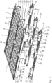
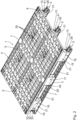
- the pallet illustrated in its entirety comprises a pallet-like support arrangement 1 and three skid arrangements 2.
- the skid arrangements 2 can be arranged on the support arrangement 1.
- the skid arrangements 2 are fixedly but detachably arranged on the support arrangement 1.
- Coupling arrangements 3 are effective between the support arrangement 1 and each skid arrangement 2.
- the support arrangement 1 comprises a support plate 4, which offers or forms a flat, upwardly facing support surface 5 for at least one item to be supported (not shown).
- the support plate 4 is rectangular and has a plurality of rectangular hollow chambers that are open at the top and bottom.
- the support surface 5 is formed by free ends of webs of the hollow chambers.
- the support arrangement 1 has several partial blocks that protrude downwards from the support plate 4 and form a base 6 for placing on a surface (not shown), such as the ground, or for supporting against it.
- a surface not shown
- Three partial blocks extend adjacent to each longitudinal edge 7 of the support arrangement 1.
- three partial blocks are arranged in a central region of the support arrangement 1 between the partial blocks arranged adjacent to the longitudinal edges 7. The partial blocks on the support arrangement side are thus arranged next to one another in three rows that extend in a longitudinal direction 8 of the support arrangement 1.
- the partial blocks arranged adjacent to transverse edges 9 of the support arrangement 1 are at least identical in type. They are assigned the reference number 10. In a central transverse plane of the support arrangement 1 there are There are partial blocks that are at least identical in type. They are assigned the reference number 11. The partial blocks 10, 11 differ from one another in terms of their construction.
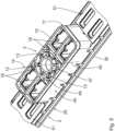
- Each partial block 11 is essentially rectangular and elongated. It has a central hollow cylinder body 12, which has several plate-like retaining webs 13 on the inside.
- the retaining webs 13 are arranged at equal angular spacing on the hollow cylinder body 12. They are located in a common plane running parallel to the base 6 and jump from the hollow cylinder body 12 towards a central axis 14 of the hollow cylinder body 12, but end at a distance from each other.
- the retaining webs 13 are arranged at a distance from the base 6.
- Each partial block 11 has several reinforcing webs 16 in addition to an outer wall 15.
- Each partial block 10 is essentially rectangular and elongated. It has an outer wall 17 and inner stiffening webs. Each partial block 10 has a first dovetail groove 18 and a second dovetail groove 19 at the bottom, which are open towards the adjacent base 6.
- Each first dovetail groove 18 has two first openings 20 lying opposite one another on the sides. Each first dovetail groove 18 is delimited by two first flanks 21 lying opposite one another, which extend from the adjacent base 6 away from one another in the direction of the support plate 4. Furthermore, each first dovetail groove 18 is delimited by an inner first base 22, which extends parallel to the associated base 6 between the first flanks 21. The first flanks 21 and the first base 22 are part of the respective Partial block 10. Each first dovetail groove 18 extends in a circular arc around the central axis 14 of the partial block 11 arranged in this row.
- Every second dovetail groove 19 has two opposing second openings 23 on the sides. Every second dovetail groove 19 is delimited by two opposing second flanks 24 which run away from each other from the adjacent base 6 in the direction of the support plate 4. Every second dovetail groove 19 is delimited by an inner second base 25 which extends parallel to the associated base 6 between the second flanks 24. The second flanks 24 and the second base 25 are part of the respective partial block 10. Every second dovetail groove 19 extends in a circular arc around the central axis 14 of the partial block 11 arranged in this row. Every second dovetail groove 19 is at a greater distance from this central axis 14 than the adjacent first dovetail groove 18. The dovetail grooves 18, 19 of each partial block 10 run at equal distances from one another. They extend curved in a transverse direction of the support arrangement 1.
- the dovetail grooves 18, 19 form coupling means. They are part of a coupling part.
- Each partial block 10 has a locking recess 26 on the front side, adjacent to the transverse edge 9, the inlet opening 27 of which faces away from a transverse plane of the support arrangement 1 or the partial block 11 arranged in this row.
- Each locking recess 26 is spatially delimited by two opposing side walls 28 which extend in the longitudinal direction 8 of the support arrangement 1.
- Each locking recess 26 forms a locking means.
- the partial blocks 11 arranged in a row form outer partial blocks, while each partial block 10 in this row forms an inner or middle partial block.
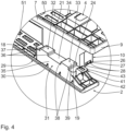
- Each skid assembly 2 comprises a rigid base rail 29 which extends substantially straight and is rectangular.
- Each base rail 29 has a base 30 at the bottom.
- Three partial blocks protrude from each base strip 29 opposite the respective standing surface 30. These partial blocks are arranged at a distance from one another and have a distance from one another that corresponds to the distance between the partial blocks 10, 11 of the support arrangement 1 arranged in a row.
- Each runner arrangement 2 has two outer partial blocks 31 which are structurally identical and are arranged in opposite end regions of the respective base strip 29.
- Each partial block 31 has a first pin 32 and a second pin 33 at the top, which protrude upwards from a head surface 34 of the respective partial block 31 and are each designed as a dovetail.
- Each pin 32, 33 extends between opposite side walls 35 of the respective partial block 31 or in a transverse direction of the respective runner arrangement 2.
- the first pins 32 are complementary to the first dovetail grooves 18.
- Each first pin 32 has two opposite first side flanks 36, which are formed by the adjacent Head surface 34 run away from each other and delimit a free first roof surface 37.
- the second pins 33 are designed to be complementary to the second dovetail grooves 19.
- Each second pin 33 has two opposing second side flanks 38 which extend away from each other from the respective head surface 34, delimiting a free second roof surface 39.
- the roof surfaces 37, 39 extend parallel to the adjacent head surface 34.
- Each pin 32, 33 extends in a circular arc around a central axis 40 of the respective runner arrangement 2, which extends perpendicular to the associated standing surface 30.
- the pins 32, 33 form counter-coupling means for the coupling means. They are part of a counter-coupling part.
- the dovetail grooves 18, 19 and the pins 32, 33 are part of dovetail devices.
- Each partial block 31 carries a locking body 41, which is preferably resiliently displaceable.
- the locking bodies 41 of each runner arrangement 2 face away from one another. They are designed to complement the locking recesses 26 and form counter-locking means for the locking means.
- Each locking body 41 has two opposing locking surfaces 42 which run parallel to one another and extend flat. The distance between the locking surfaces 42 corresponds to the distance between the side walls 28 which delimit a locking recess 26.
- the locking surfaces 42 extend perpendicular to the adjacent base surface 30 and parallel to a longitudinal direction 44 of the corresponding runner arrangement 2.
- Each locking body 41 has a free actuating surface 43 at the top.
- Each runner arrangement 2 also comprises a central partial block 45 which is arranged centrally between the partial blocks 31 of the respective runner arrangement 2.
- Each partial block 45 has a head surface 46 which faces away from the standing surface 30 of the respective runner arrangement 2.
- Each partial block 45 comprises a cylinder body 47 which is preferably designed as a hollow cylinder body and projects vertically upwards or outwards from the head surface 46 of the respective partial block 45.
- Each cylinder body 47 has an outer diameter D which is preferably slightly smaller than an imaginary diameter or circle formed by free ends of the retaining webs 13.
- Each cylinder body 47 has retaining projections 48 on the outside, which project radially outwards and are arranged at a uniform angular distance from one another.
- Each retaining projection 48 has a width in the circumferential direction around the associated cylinder body 47 that is smaller than a corresponding width of a retaining web 13 in the circumferential direction around the associated hollow cylinder body 12.
- the number of retaining projections 48 of a partial block 45 corresponds to the number of retaining webs 13 of a partial block 11.
- the retaining projections 48 are arranged at a distance from the adjacent head surface 46 to form a retaining surface 49.
- the retaining surfaces 49 face the adjacent head surface 46.
- a distance between the head surface 46 and an adjacent retaining projection 48 is slightly larger than the thickness of a retaining web 13.
- the retaining projections 48 have alignment flanks 52 opposite the retaining surfaces 49, which extend obliquely from the associated cylinder body 47 in the direction of the adjacent head surface 46.
- the central axis 40 of the respective runner arrangement 2 is defined by the cylinder body 47.
- the retaining webs 13 form coupling means for the retaining projections 48, which form counter-coupling means.
- the retaining webs 13 are part of a coupling part.
- the retaining projections 48 are part of a counter-coupling part.
- the retaining projections 48 and the retaining webs 13 are part of a bayonet device.
- the support plate 4 has several reinforcing elements 50 which extend in the longitudinal direction 8 and are arranged at a distance from one another. Two of the reinforcing elements 50 extend adjacent to the longitudinal edges 7, while a further reinforcing element 50 extends centrally between them in the longitudinal direction 8. It is expedient if corresponding reinforcing elements 50 also extend on the rear side of the support plate 4. The reinforcing elements 50 are arranged in corresponding recesses in the support plate 4.
- Each skid arrangement 2 has two reinforcing elements 51 which extend on top of the respective floor element 29 in the longitudinal direction 44 between the partial blocks 31, 45.
- corresponding reinforcing elements 51 are also arranged on an underside of the respective floor element 29, corresponding reinforcing elements 51 are also arranged.
- the reinforcing elements 51 are arranged in corresponding recesses of the respective runner arrangement 2.
- the support arrangement 1 can be used independently as a pallet.
- the support surface 5 of the support arrangement 1 is capable of carrying goods, for example in stacked form.
- the support arrangement 1 can be placed securely on the ground via its partial blocks 10, 11.
- the support plate 4 is arranged at a distance from the ground.
- a lifting device can move between the partial blocks 10, 11 under the support plate 4.
- Skid assemblies 2 can be attached to the support assembly 1 in a detachable manner and without tools, for example to enable use in a high-bay warehouse or in automated conveyor systems.
- the respective partial block 11 of the support arrangement 1 and the cylinder body 47 of the partial block 45 of the respective skid arrangement 2 are arranged one above the other.
- the alignment flanks 52 lead to an alignment between the cylinder body 47 of the respective skid arrangement 2 and the associated hollow cylinder body 12 of the support arrangement 1.
- the center axes 14, 40 are then aligned with one another.
- the retaining projections 48 and the retaining webs 13 are aligned with each other for the assembly of the skid arrangement 2 by a relative pivoting movement between the support arrangement 1 and the respective skid arrangement 2 about the respective central axis 14 or 40, that the retaining projections 48 are located in front of or adjacent to gaps between the adjacent retaining webs 13.
- the retaining projections 48 then penetrate the gaps. A movement takes place between the support arrangement 1 and the respective skid arrangement 2 along the respective center axis 14 or 40. This insertion process is completed when the standing surface 6 of the then upper partial block 11 is arranged adjacent to the head surface 46 of the then lower partial block 45 or rests on top of it.
- the retaining projections 48 then have a distance from the support plate 4 that is smaller than the distance of the retaining webs 13 from the support plate 4.
- the respective skid arrangement 2 is manually pivoted about its central axis 40, which is vertically oriented.
- this pivoting movement leads to a relative pivoting movement between the retaining webs 13 and the retaining projections 48.
- the retaining projections 48 move over the retaining webs 13 and engage behind them. They are then located directly above the retaining webs 13, so that the retaining surfaces 49 face the adjacent retaining webs 13.
- the retaining webs 13 are located between the head surface 46 and the retaining projections 48, which causes the respective skid arrangement 2 to be fixed locally on the support arrangement 1 in the direction of the central axis 14 or 40.
- the pins 32, 33 of the respective skid arrangement 2 are inserted into the respective dovetail groove 18 or 19 via their openings 22 or 23.
- the pins 32, 33 of a partial block 31 of the respective skid arrangement 2 for example, from the outside into the associated partial block 10 of the support arrangement 1, while the pins 32, 33 of the other partial block 31 of the respective skid arrangement 2 enter from the inside into the associated partial block 10 of the support arrangement 1.
- the pins 32, 33 of the two partial blocks 31 enter from opposite sides into the associated partial blocks 10 of the support arrangement 1.
- the pins 32, 33 engage with the respective dovetail groove 18 or 19.
- the side flanks 36 or 38 are arranged adjacent to the flanks 21 or 24 of the dovetail grooves 18 or 19 or they rest against them.
- the locking bodies 41 have entered the associated locking recess 26 via the respective inlet opening 27.
- the locking surfaces 42 of the respective locking body 41 are arranged adjacent to the side walls 28 or rest against them, which prevents unwanted pivoting between the support arrangement 1 and the respective skid arrangement 2 about the central axis 14 or 40.
- the partial blocks 10, 31 form complete blocks, while the partial blocks 11, 45 form further complete blocks.
- the pallet can thus be placed over the base 30 of the respective skid arrangement 2 and thus naturally has a greater height than without the skid arrangements 2.
- a lifting device can be moved between the skid arrangements 2 under the support plate 4.
- the assembly is identical for all skid arrangements 2.
- the support arrangement 1 when assembling a skid arrangement 2, the support arrangement 1 is placed on the corresponding skid arrangement 2. What is essential is first a relative plug-in movement between the support arrangement 1 and the respective skid arrangement 2 and then a pivoting movement.
- Disassembly is essentially carried out in a similar way. To do this, the locking bodies 41 are first disengaged from the locking recesses 26, which is possible by applying pressure from above to the actuating surfaces 43.
- Fig. 1 to 3 The range according to Fig. 1 to 3 is elongated; that is, it is longer than it is wide.
- the pallet is square or essentially square.
Landscapes
- Engineering & Computer Science (AREA)
- Mechanical Engineering (AREA)
- Pallets (AREA)
Applications Claiming Priority (3)
| Application Number | Priority Date | Filing Date | Title |
|---|---|---|---|
| DE102019203480.2A DE102019203480B4 (de) | 2019-03-14 | 2019-03-14 | Palette |
| EP20711153.5A EP3938285A1 (fr) | 2019-03-14 | 2020-03-12 | Palette |
| PCT/EP2020/056685 WO2020182954A1 (fr) | 2019-03-14 | 2020-03-12 | Palette |
Related Parent Applications (1)
| Application Number | Title | Priority Date | Filing Date |
|---|---|---|---|
| EP20711153.5A Division EP3938285A1 (fr) | 2019-03-14 | 2020-03-12 | Palette |
Publications (4)
| Publication Number | Publication Date |
|---|---|
| EP4389629A2 true EP4389629A2 (fr) | 2024-06-26 |
| EP4389629A3 EP4389629A3 (fr) | 2024-09-04 |
| EP4389629B1 EP4389629B1 (fr) | 2025-09-17 |
| EP4389629C0 EP4389629C0 (fr) | 2025-09-17 |
Family
ID=69810867
Family Applications (2)
| Application Number | Title | Priority Date | Filing Date |
|---|---|---|---|
| EP24175580.0A Active EP4389629B1 (fr) | 2019-03-14 | 2020-03-12 | Palette |
| EP20711153.5A Pending EP3938285A1 (fr) | 2019-03-14 | 2020-03-12 | Palette |
Family Applications After (1)
| Application Number | Title | Priority Date | Filing Date |
|---|---|---|---|
| EP20711153.5A Pending EP3938285A1 (fr) | 2019-03-14 | 2020-03-12 | Palette |
Country Status (6)
| Country | Link |
|---|---|
| US (1) | US11731804B2 (fr) |
| EP (2) | EP4389629B1 (fr) |
| CN (1) | CN113811492B (fr) |
| DE (2) | DE102019203480B4 (fr) |
| ES (1) | ES3046819T3 (fr) |
| WO (1) | WO2020182954A1 (fr) |
Families Citing this family (9)
| Publication number | Priority date | Publication date | Assignee | Title |
|---|---|---|---|---|
| DE102019203480B4 (de) | 2019-03-14 | 2020-11-12 | 2In1 Ag | Palette |
| NO346684B1 (no) * | 2019-08-15 | 2022-11-21 | Bewi Norplasta As | Transportpall |
| US12325552B2 (en) * | 2020-12-31 | 2025-06-10 | Sabic Global Technologies B.V. | Plastic pallet with removable elastomer footpads |
| DE102021203137A1 (de) | 2021-03-29 | 2022-09-29 | 2In1 Ag | Palette |
| CN113602630B (zh) * | 2021-09-10 | 2023-05-30 | 广东特帅科技股份有限公司 | 组合式塑胶栈板 |
| US20230078405A1 (en) * | 2021-09-14 | 2023-03-16 | Quantronix, Inc. | Apparatus and methods for pallet load monitoring |
| USD1066445S1 (en) | 2022-09-08 | 2025-03-11 | DuraPlas, LP | Equipment support pad |
| WO2025029536A2 (fr) * | 2023-08-01 | 2025-02-06 | Reusables Development Group, Llc | Unité de transport à pieds amovibles |
| US12515846B2 (en) | 2024-04-26 | 2026-01-06 | Sartorius Stedim North America Inc. | Bulk shipper pallet and isolator for bulk freezing applications |
Citations (8)
| Publication number | Priority date | Publication date | Assignee | Title |
|---|---|---|---|---|
| GB2280663A (en) | 1993-08-03 | 1995-02-08 | Mckechnie Uk Ltd | Pallet |
| US5445084A (en) | 1992-04-10 | 1995-08-29 | Antal Trading, Ltd. | Normed transport pallet |
| DE20105233U1 (de) | 2001-03-24 | 2001-10-18 | Ludwig Gebhardt GmbH & Co. Betriebs-KG, 93413 Cham | Palette |
| DE102007009762A1 (de) | 2007-02-27 | 2008-08-28 | Werzalit Gmbh + Co. Kg | Palette zum vielseitigen Einsatz in Produktion, Logistik und Transport |
| EP2216255A1 (fr) | 2009-02-10 | 2010-08-11 | Paul Craemer GmbH | Palette en plastique doté d'un patin renforcé |
| US20140000494A1 (en) | 2010-12-01 | 2014-01-02 | Konsortium Two In One | Modular pallet |
| CN203946355U (zh) | 2013-12-31 | 2014-11-19 | 浙江荣信模具塑料有限公司 | 卡扣式托盘 |
| DE102019203480A1 (de) | 2019-03-14 | 2020-09-17 | 2In1 Ag | Palette |
Family Cites Families (45)
| Publication number | Priority date | Publication date | Assignee | Title |
|---|---|---|---|---|
| DE1756873A1 (de) * | 1968-07-25 | 1970-08-27 | Lauterberger Blechwarenfabrik | Stapelpalette |
| US3824933A (en) * | 1972-09-14 | 1974-07-23 | Jaw Bar Plastics Corp | Load bearing pallet and interlock |
| FR2564430B1 (fr) * | 1984-05-18 | 1987-01-16 | Latec | Palette pour la manutention et le stockage de charges |
| US5117762A (en) * | 1990-02-26 | 1992-06-02 | Shuert Lyle H | Rackable plastic pallet |
| US5417167A (en) * | 1993-03-03 | 1995-05-23 | Salflex Polymers Ltd. | Plastic pallet |
| US6029583A (en) * | 1996-07-02 | 2000-02-29 | Allibert-Contico, L.L.C. | Pallet with attachable upper and lower members |
| USD409814S (en) * | 1997-12-23 | 1999-05-11 | Ecoplastic Pallets, Inc. | Pallet |
| US6305301B1 (en) * | 1999-07-26 | 2001-10-23 | Piper Plastics, Inc. | Support structures such as pallets and methods and systems relating thereto |
| US6109190A (en) * | 1999-10-19 | 2000-08-29 | Plastic Pallet Production, Inc. | Materials handling pallet |
| ES2172403B1 (es) * | 2000-06-07 | 2003-12-16 | Plaspalet S A | Modulos premoldeados para la confeccion de palets y palets obtenidos. |
| US6622641B2 (en) * | 2001-10-03 | 2003-09-23 | Rehrig Pacific Company | Pallet |
| GB0216560D0 (en) * | 2002-07-17 | 2002-08-28 | D W Plastics Nv | Pallets provided with a transponder |
| US20050268824A1 (en) * | 2004-06-07 | 2005-12-08 | Williams Larry T Jr | Easily assembled and repairable plastic shipping pallet |
| US7578244B2 (en) * | 2004-06-07 | 2009-08-25 | Williams Jr Larry Thomas | Easily assembled and repairable plastic shipping pallet |
| US20060096508A1 (en) * | 2004-11-10 | 2006-05-11 | Rafael Herring | Modular pallet |
| US7779765B2 (en) * | 2006-03-03 | 2010-08-24 | Daniel Kelly | Pallet with telescoped leg assemblies |
| DE202006006526U1 (de) * | 2006-04-13 | 2006-07-13 | Mark Arinstein Maschinen & Anlagen Gmbh | Palette mit hoher Formstabilität und Tragkraft |
| US7748329B2 (en) * | 2006-07-24 | 2010-07-06 | Rehrig Pacific Company | Pallet assembly |
| US7779763B2 (en) * | 2006-12-19 | 2010-08-24 | Schoeller Arca Systems Services Gmbh | Transport pallet |
| US8141500B2 (en) * | 2007-03-30 | 2012-03-27 | Chep Technology Pty Limited | Plastic pallet with sleeved reinforcing rods and associated method for making the same |
| US7490561B1 (en) * | 2008-01-24 | 2009-02-17 | Huang Jung Chou | Pallet assembly |
| DE102008006388A1 (de) * | 2008-01-29 | 2009-08-13 | Georg Utz Holding Ag | Palette |
| CN101251629B (zh) * | 2008-03-25 | 2010-06-16 | 浙江万马集团电子有限公司 | 复合型适配器卡口座板及其生产方法 |
| DE102008022366A1 (de) * | 2008-05-06 | 2009-11-19 | Cabka Gmbh | Ladungsträger |
| US8522694B2 (en) * | 2008-06-20 | 2013-09-03 | Oria Collapsibles, Llc | Structural supporting pallet construction with improved perimeter impact absorbing capabilities |
| ES2397812T3 (es) * | 2008-07-03 | 2013-03-11 | Macro Plastics, Inc. | Contenedor de transporte |
| DE202009001258U1 (de) * | 2009-02-04 | 2009-04-09 | Schoeller Arca Systems Gmbh | Transportpalette |
| CN103068688B (zh) * | 2010-07-13 | 2016-08-03 | 迈普有限责任公司 | 塑料托盘和用于制造塑料托盘的方法 |
| CN103124680B (zh) * | 2010-07-13 | 2015-09-30 | A·R·阿芮纳产品有限公司 | 由托架底座和盖板构成的挠曲组件 |
| CO7030192A1 (es) * | 2012-02-14 | 2014-08-21 | Rehrig Pacific Co | Un ensamble de estiba que comprende una porción superior y una porción inferior |
| CH707199A2 (de) * | 2012-11-15 | 2014-05-15 | Utz Georg Holding Ag | Kunststoffpalette. |
| CN107850099A (zh) * | 2015-06-01 | 2018-03-27 | A·雷蒙德有限合伙公司 | 用于约束构件的装置 |
| CN105292679A (zh) * | 2015-10-27 | 2016-02-03 | 王明明 | 一种物流托盘 |
| CN105366164A (zh) * | 2015-11-26 | 2016-03-02 | 天津如有科技有限公司 | 一种轻质金属托盘 |
| DE102016109256B4 (de) * | 2016-05-19 | 2018-11-08 | Walther Faltsysteme Gmbh | Palette mit Koppelglied |
| US10081454B2 (en) * | 2016-11-21 | 2018-09-25 | Chep Technology Pty Limited | Plastic pallet with support blocks having pockets for pin wheeling and associated methods |
| CN206719758U (zh) * | 2017-05-08 | 2017-12-08 | 山东贝福特新材料有限公司 | 一种安全多功能智能托盘系统 |
| ES2693924B2 (es) * | 2017-06-14 | 2020-01-29 | Logicpalet World S L | Estructura desmontable para transporte de cargas |
| MY199827A (en) * | 2017-06-22 | 2023-11-23 | Swee Wun Yap | Pallet assembly |
| US20190034863A1 (en) * | 2017-07-21 | 2019-01-31 | Walmart Apollo, Llc | Shipping accuracy |
| CN207670873U (zh) * | 2017-12-29 | 2018-07-31 | 四川职业技术学院 | 一种物流托盘 |
| US20200031524A1 (en) * | 2018-07-24 | 2020-01-30 | Chep Technology Pty Limited | Wooden pallet with end deck boards and butted spacers |
| US11401073B2 (en) * | 2018-07-24 | 2022-08-02 | Chep Technology Pty Limited | Wooden pallet with butted deck boards and metal bracket supports |
| US20200031522A1 (en) * | 2018-07-25 | 2020-01-30 | Paxxal Inc. | Roto molded pallet |
| CH715550A1 (de) * | 2018-11-15 | 2020-05-15 | Utz Georg Holding Ag | Kunststoffpalette mit geschützten Kufen. |
-
2019
- 2019-03-14 DE DE102019203480.2A patent/DE102019203480B4/de active Active
-
2020
- 2020-03-12 EP EP24175580.0A patent/EP4389629B1/fr active Active
- 2020-03-12 US US17/439,240 patent/US11731804B2/en active Active
- 2020-03-12 CN CN202080035016.XA patent/CN113811492B/zh active Active
- 2020-03-12 WO PCT/EP2020/056685 patent/WO2020182954A1/fr not_active Ceased
- 2020-03-12 DE DE112020001240.9T patent/DE112020001240A5/de active Pending
- 2020-03-12 EP EP20711153.5A patent/EP3938285A1/fr active Pending
- 2020-03-12 ES ES24175580T patent/ES3046819T3/es active Active
Patent Citations (8)
| Publication number | Priority date | Publication date | Assignee | Title |
|---|---|---|---|---|
| US5445084A (en) | 1992-04-10 | 1995-08-29 | Antal Trading, Ltd. | Normed transport pallet |
| GB2280663A (en) | 1993-08-03 | 1995-02-08 | Mckechnie Uk Ltd | Pallet |
| DE20105233U1 (de) | 2001-03-24 | 2001-10-18 | Ludwig Gebhardt GmbH & Co. Betriebs-KG, 93413 Cham | Palette |
| DE102007009762A1 (de) | 2007-02-27 | 2008-08-28 | Werzalit Gmbh + Co. Kg | Palette zum vielseitigen Einsatz in Produktion, Logistik und Transport |
| EP2216255A1 (fr) | 2009-02-10 | 2010-08-11 | Paul Craemer GmbH | Palette en plastique doté d'un patin renforcé |
| US20140000494A1 (en) | 2010-12-01 | 2014-01-02 | Konsortium Two In One | Modular pallet |
| CN203946355U (zh) | 2013-12-31 | 2014-11-19 | 浙江荣信模具塑料有限公司 | 卡扣式托盘 |
| DE102019203480A1 (de) | 2019-03-14 | 2020-09-17 | 2In1 Ag | Palette |
Also Published As
| Publication number | Publication date |
|---|---|
| DE112020001240A5 (de) | 2021-12-02 |
| EP4389629B1 (fr) | 2025-09-17 |
| CN113811492A (zh) | 2021-12-17 |
| CN113811492B (zh) | 2024-12-10 |
| EP4389629A3 (fr) | 2024-09-04 |
| EP4389629C0 (fr) | 2025-09-17 |
| DE102019203480A1 (de) | 2020-09-17 |
| US11731804B2 (en) | 2023-08-22 |
| WO2020182954A1 (fr) | 2020-09-17 |
| EP3938285A1 (fr) | 2022-01-19 |
| ES3046819T3 (en) | 2025-12-02 |
| DE102019203480B4 (de) | 2020-11-12 |
| US20220144487A1 (en) | 2022-05-12 |
Similar Documents
| Publication | Publication Date | Title |
|---|---|---|
| EP4389629B1 (fr) | Palette | |
| EP2181046B1 (fr) | Palette navette pour système de stockage | |
| EP2646329B1 (fr) | Palette modulaire | |
| EP0882660A1 (fr) | Etagère de stockage et de préparation de commandes | |
| EP3684701B1 (fr) | Palette en matière plastique et support de charges à grande capacité | |
| WO2020099994A1 (fr) | Palette en matière plastique dotée de patins protégés | |
| EP3877276A1 (fr) | Palette en plastique pourvue d'éléments de renfort | |
| DE202017004490U1 (de) | Ladungsträger zur Aufnahme von Ladungsgut | |
| EP4146552B1 (fr) | Palette en plastique à liaison par encliquetage | |
| EP2592010A1 (fr) | Palette | |
| DE3728647C2 (fr) | ||
| EP3736223B1 (fr) | Fond de palette pour un récipient de transport et récipient de transport | |
| DE102009039803A1 (de) | Modularer Transportbehälter | |
| DE4229698A1 (de) | Palette zur Aufnahme von Rädern oder Radfelgen | |
| DE102014011070B4 (de) | Palette | |
| EP1243518A2 (fr) | Palette avec plaque de renfort | |
| EP1219543A2 (fr) | Palette en plastique | |
| WO2018184709A1 (fr) | Palette en matière plastique comprenant des éléments de renforcement | |
| DE4403743C2 (de) | Palette für die Aufnahme von Lagergut | |
| EP4313788A1 (fr) | Palette | |
| DE202005009622U1 (de) | Kunststoff-Palette | |
| EP0846624B1 (fr) | Palette en plastique avec pieds élastiques | |
| EP4291513A1 (fr) | Installation de transport et de stockage d'articles de transport | |
| EP4043358A1 (fr) | Porte-charge | |
| DE7200808U (de) | Palette |
Legal Events
| Date | Code | Title | Description |
|---|---|---|---|
| PUAI | Public reference made under article 153(3) epc to a published international application that has entered the european phase |
Free format text: ORIGINAL CODE: 0009012 |
|
| STAA | Information on the status of an ep patent application or granted ep patent |
Free format text: STATUS: THE APPLICATION HAS BEEN PUBLISHED |
|
| AC | Divisional application: reference to earlier application |
Ref document number: 3938285 Country of ref document: EP Kind code of ref document: P |
|
| AK | Designated contracting states |
Kind code of ref document: A2 Designated state(s): AL AT BE BG CH CY CZ DE DK EE ES FI FR GB GR HR HU IE IS IT LI LT LU LV MC MK MT NL NO PL PT RO RS SE SI SK SM TR |
|
| REG | Reference to a national code |
Ref country code: DE Ref legal event code: R079 Free format text: PREVIOUS MAIN CLASS: B65D0019320000 Ipc: B65D0019240000 Ref country code: DE Ref legal event code: R079 Ref document number: 502020011954 Country of ref document: DE Free format text: PREVIOUS MAIN CLASS: B65D0019320000 Ipc: B65D0019240000 |
|
| PUAL | Search report despatched |
Free format text: ORIGINAL CODE: 0009013 |
|
| AK | Designated contracting states |
Kind code of ref document: A3 Designated state(s): AL AT BE BG CH CY CZ DE DK EE ES FI FR GB GR HR HU IE IS IT LI LT LU LV MC MK MT NL NO PL PT RO RS SE SI SK SM TR |
|
| RIC1 | Information provided on ipc code assigned before grant |
Ipc: B65D 19/32 20060101ALI20240731BHEP Ipc: B65D 19/24 20060101AFI20240731BHEP |
|
| STAA | Information on the status of an ep patent application or granted ep patent |
Free format text: STATUS: REQUEST FOR EXAMINATION WAS MADE |
|
| 17P | Request for examination filed |
Effective date: 20241210 |
|
| RAP3 | Party data changed (applicant data changed or rights of an application transferred) |
Owner name: 2IN1 AG |
|
| GRAP | Despatch of communication of intention to grant a patent |
Free format text: ORIGINAL CODE: EPIDOSNIGR1 |
|
| STAA | Information on the status of an ep patent application or granted ep patent |
Free format text: STATUS: GRANT OF PATENT IS INTENDED |
|
| INTG | Intention to grant announced |
Effective date: 20250508 |
|
| GRAS | Grant fee paid |
Free format text: ORIGINAL CODE: EPIDOSNIGR3 |
|
| GRAA | (expected) grant |
Free format text: ORIGINAL CODE: 0009210 |
|
| STAA | Information on the status of an ep patent application or granted ep patent |
Free format text: STATUS: THE PATENT HAS BEEN GRANTED |
|
| AC | Divisional application: reference to earlier application |
Ref document number: 3938285 Country of ref document: EP Kind code of ref document: P |
|
| AK | Designated contracting states |
Kind code of ref document: B1 Designated state(s): AL AT BE BG CH CY CZ DE DK EE ES FI FR GB GR HR HU IE IS IT LI LT LU LV MC MK MT NL NO PL PT RO RS SE SI SK SM TR |
|
| REG | Reference to a national code |
Ref country code: GB Ref legal event code: FG4D Free format text: NOT ENGLISH |
|
| REG | Reference to a national code |
Ref country code: CH Ref legal event code: EP |
|
| REG | Reference to a national code |
Ref country code: DE Ref legal event code: R096 Ref document number: 502020011954 Country of ref document: DE |
|
| REG | Reference to a national code |
Ref country code: IE Ref legal event code: FG4D Free format text: LANGUAGE OF EP DOCUMENT: GERMAN |
|
| U01 | Request for unitary effect filed |
Effective date: 20250926 |
|
| U07 | Unitary effect registered |
Designated state(s): AT BE BG DE DK EE FI FR IT LT LU LV MT NL PT RO SE SI Effective date: 20251008 |
|
| REG | Reference to a national code |
Ref country code: ES Ref legal event code: FG2A Ref document number: 3046819 Country of ref document: ES Kind code of ref document: T3 Effective date: 20251202 |
|
| PG25 | Lapsed in a contracting state [announced via postgrant information from national office to epo] |
Ref country code: NO Free format text: LAPSE BECAUSE OF FAILURE TO SUBMIT A TRANSLATION OF THE DESCRIPTION OR TO PAY THE FEE WITHIN THE PRESCRIBED TIME-LIMIT Effective date: 20251217 |
|
| PG25 | Lapsed in a contracting state [announced via postgrant information from national office to epo] |
Ref country code: HR Free format text: LAPSE BECAUSE OF FAILURE TO SUBMIT A TRANSLATION OF THE DESCRIPTION OR TO PAY THE FEE WITHIN THE PRESCRIBED TIME-LIMIT Effective date: 20250917 |
|
| PG25 | Lapsed in a contracting state [announced via postgrant information from national office to epo] |
Ref country code: GR Free format text: LAPSE BECAUSE OF FAILURE TO SUBMIT A TRANSLATION OF THE DESCRIPTION OR TO PAY THE FEE WITHIN THE PRESCRIBED TIME-LIMIT Effective date: 20251218 |
|
| PG25 | Lapsed in a contracting state [announced via postgrant information from national office to epo] |
Ref country code: RS Free format text: LAPSE BECAUSE OF FAILURE TO SUBMIT A TRANSLATION OF THE DESCRIPTION OR TO PAY THE FEE WITHIN THE PRESCRIBED TIME-LIMIT Effective date: 20251217 |
|
| REG | Reference to a national code |
Ref country code: CH Ref legal event code: U11 Free format text: ST27 STATUS EVENT CODE: U-0-0-U10-U11 (AS PROVIDED BY THE NATIONAL OFFICE) Effective date: 20260401 |
|
| PG25 | Lapsed in a contracting state [announced via postgrant information from national office to epo] |
Ref country code: SM Free format text: LAPSE BECAUSE OF FAILURE TO SUBMIT A TRANSLATION OF THE DESCRIPTION OR TO PAY THE FEE WITHIN THE PRESCRIBED TIME-LIMIT Effective date: 20250917 |
|
| PGFP | Annual fee paid to national office [announced via postgrant information from national office to epo] |
Ref country code: GB Payment date: 20260324 Year of fee payment: 7 |
|
| PG25 | Lapsed in a contracting state [announced via postgrant information from national office to epo] |
Ref country code: IS Free format text: LAPSE BECAUSE OF FAILURE TO SUBMIT A TRANSLATION OF THE DESCRIPTION OR TO PAY THE FEE WITHIN THE PRESCRIBED TIME-LIMIT Effective date: 20260117 |
|
| PG25 | Lapsed in a contracting state [announced via postgrant information from national office to epo] |
Ref country code: CZ Free format text: LAPSE BECAUSE OF FAILURE TO SUBMIT A TRANSLATION OF THE DESCRIPTION OR TO PAY THE FEE WITHIN THE PRESCRIBED TIME-LIMIT Effective date: 20250917 |
|
| PGFP | Annual fee paid to national office [announced via postgrant information from national office to epo] |
Ref country code: PL Payment date: 20260217 Year of fee payment: 7 |
|
| PG25 | Lapsed in a contracting state [announced via postgrant information from national office to epo] |
Ref country code: SK Free format text: LAPSE BECAUSE OF FAILURE TO SUBMIT A TRANSLATION OF THE DESCRIPTION OR TO PAY THE FEE WITHIN THE PRESCRIBED TIME-LIMIT Effective date: 20250917 |
|
| U20 | Renewal fee for the european patent with unitary effect paid |
Year of fee payment: 7 Effective date: 20260319 |